2001 SUZUKI GRAND VITARA Drive train
[x] Cancel search: Drive trainPage 512 of 656

INSTRUMENTATION/DRIVER INFORMATION 8C-1
8C
SECTION 8C
INSTRUMENTATION/DRIVER INFORMATION
CONTENTS
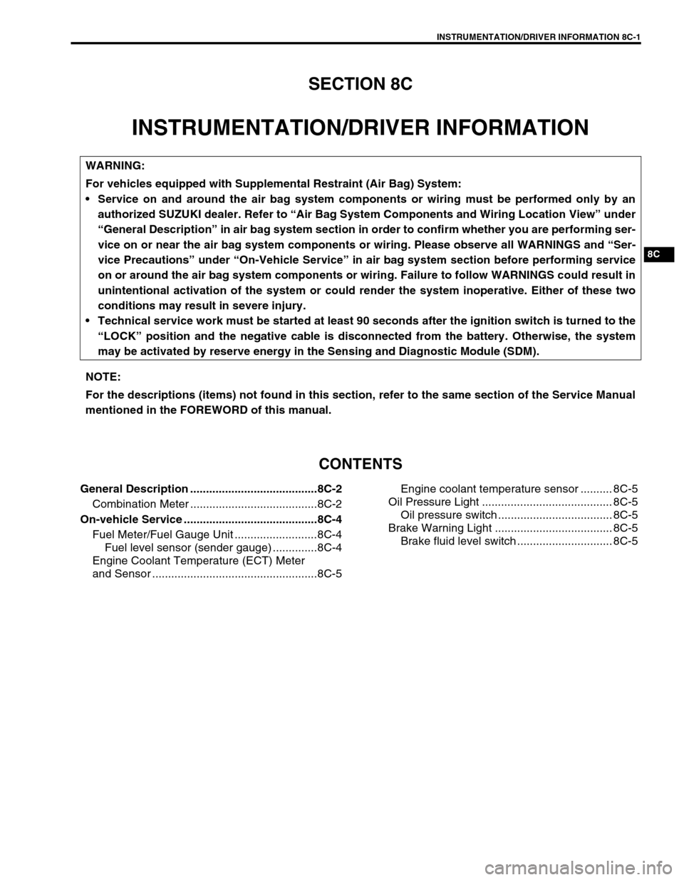
General Description ........................................8C-2
Combination Meter ........................................8C-2
On-vehicle Service ..........................................8C-4
Fuel Meter/Fuel Gauge Unit ..........................8C-4
Fuel level sensor (sender gauge) ..............8C-4
Engine Coolant Temperature (ECT) Meter
and Sensor ....................................................8C-5Engine coolant temperature sensor .......... 8C-5
Oil Pressure Light ......................................... 8C-5
Oil pressure switch .................................... 8C-5
Brake Warning Light ..................................... 8C-5
Brake fluid level switch .............................. 8C-5
WARNING:
For vehicles equipped with Supplemental Restraint (Air Bag) System:
Service on and around the air bag system components or wiring must be performed only by an
authorized SUZUKI dealer. Refer to “Air Bag System Components and Wiring Location View” under
“General Description” in air bag system section in order to confirm whether you are performing ser-
vice on or near the air bag system components or wiring. Please observe all WARNINGS and “Ser-
vice Precautions” under “On-Vehicle Service” in air bag system section before performing service
on or around the air bag system components or wiring. Failure to follow WARNINGS could result in
unintentional activation of the system or could render the system inoperative. Either of these two
conditions may result in severe injury.
Technical service work must be started at least 90 seconds after the ignition switch is turned to the
“LOCK” position and the negative cable is disconnected from the battery. Otherwise, the system
may be activated by reserve energy in the Sensing and Diagnostic Module (SDM).
NOTE:
For the descriptions (items) not found in this section, refer to the same section of the Service Manual
mentioned in the FOREWORD of this manual.
Page 522 of 656

CRUISE CONTROL SYSTEM 8E-1
6F1
6F2
6G
6H
6K
7A
7A1
7B1
7C1
7D
7E
8E
8A
8B
8C
8D
8B
9
10
10A
10B
SECTION 8E
CRUISE CONTROL SYSTEM
CONTENTS
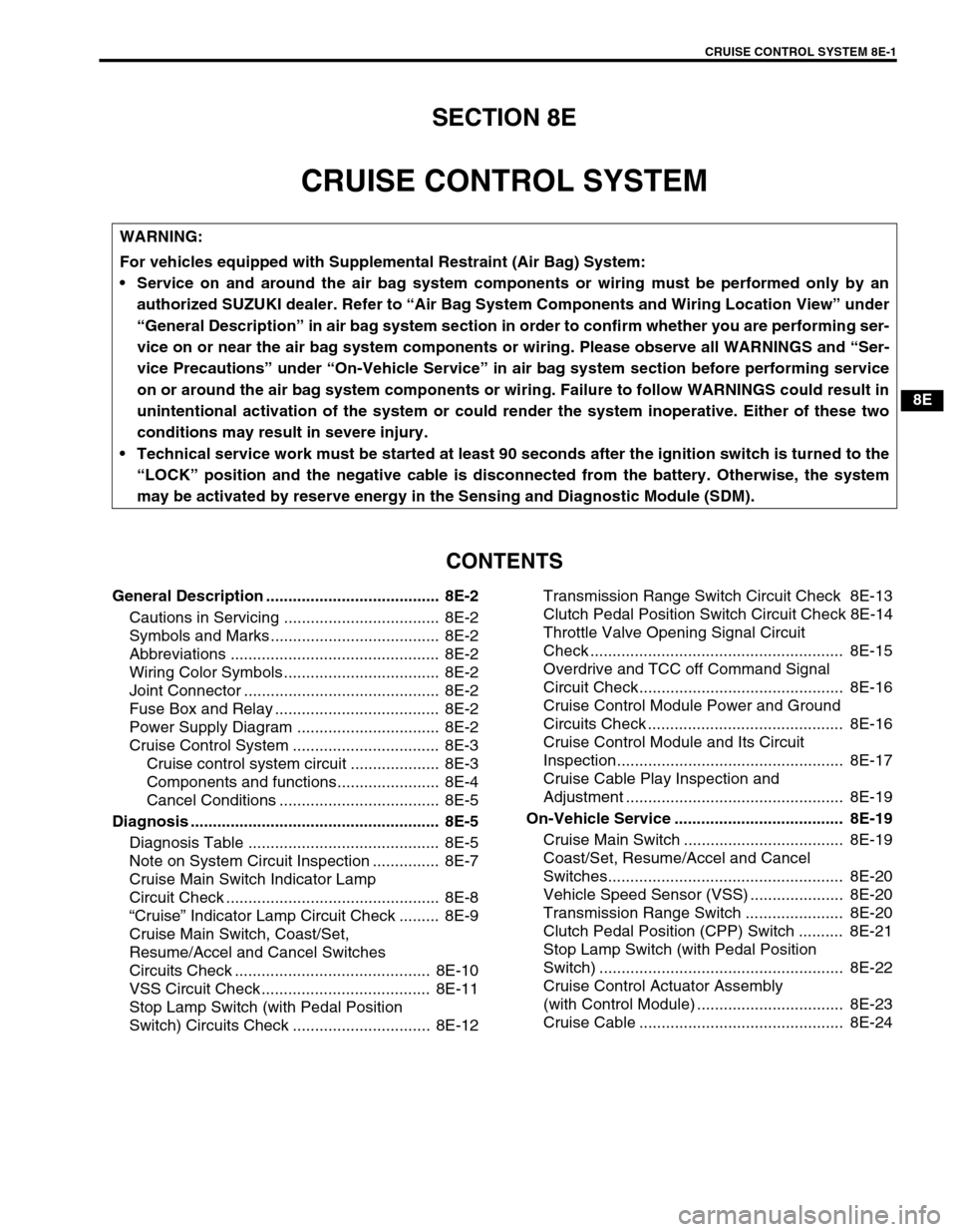
General Description ....................................... 8E-2
Cautions in Servicing ................................... 8E-2
Symbols and Marks ...................................... 8E-2
Abbreviations ............................................... 8E-2
Wiring Color Symbols ................................... 8E-2
Joint Connector ............................................ 8E-2
Fuse Box and Relay ..................................... 8E-2
Power Supply Diagram ................................ 8E-2
Cruise Control System ................................. 8E-3
Cruise control system circuit .................... 8E-3
Components and functions....................... 8E-4
Cancel Conditions .................................... 8E-5
Diagnosis ........................................................ 8E-5
Diagnosis Table ........................................... 8E-5
Note on System Circuit Inspection ............... 8E-7
Cruise Main Switch Indicator Lamp
Circuit Check ................................................ 8E-8
“Cruise” Indicator Lamp Circuit Check ......... 8E-9
Cruise Main Switch, Coast/Set,
Resume/Accel and Cancel Switches
Circuits Check ............................................ 8E-10
VSS Circuit Check ...................................... 8E-11
Stop Lamp Switch (with Pedal Position
Switch) Circuits Check ............................... 8E-12Transmission Range Switch Circuit Check 8E-13
Clutch Pedal Position Switch Circuit Check 8E-14
Throttle Valve Opening Signal Circuit
Check ......................................................... 8E-15
Overdrive and TCC off Command Signal
Circuit Check.............................................. 8E-16
Cruise Control Module Power and Ground
Circuits Check ............................................ 8E-16
Cruise Control Module and Its Circuit
Inspection................................................... 8E-17
Cruise Cable Play Inspection and
Adjustment ................................................. 8E-19
On-Vehicle Service ...................................... 8E-19
Cruise Main Switch .................................... 8E-19
Coast/Set, Resume/Accel and Cancel
Switches..................................................... 8E-20
Vehicle Speed Sensor (VSS) ..................... 8E-20
Transmission Range Switch ...................... 8E-20
Clutch Pedal Position (CPP) Switch .......... 8E-21
Stop Lamp Switch (with Pedal Position
Switch) ....................................................... 8E-22
Cruise Control Actuator Assembly
(with Control Module) ................................. 8E-23
Cruise Cable .............................................. 8E-24
WARNING:
For vehicles equipped with Supplemental Restraint (Air Bag) System:
Service on and around the air bag system components or wiring must be performed only by an
authorized SUZUKI dealer. Refer to “Air Bag System Components and Wiring Location View” under
“General Description” in air bag system section in order to confirm whether you are performing ser-
vice on or near the air bag system components or wiring. Please observe all WARNINGS and “Ser-
vice Precautions” under “On-Vehicle Service” in air bag system section before performing service
on or around the air bag system components or wiring. Failure to follow WARNINGS could result in
unintentional activation of the system or could render the system inoperative. Either of these two
conditions may result in severe injury.
Technical service work must be started at least 90 seconds after the ignition switch is turned to the
“LOCK” position and the negative cable is disconnected from the battery. Otherwise, the system
may be activated by reserve energy in the Sensing and Diagnostic Module (SDM).
Page 569 of 656

10-2 RESTRAINT SYSTEM
General Description
SEAT BELT WITH ELR
The seat belt with Emergency Locking Retractor (ELR) is designed so that it locks immediately (to prevent the
webbing from being pulled out of the retractor any further) when any of the following items is detected as
exceeding each set value; speed at which the webbing is pulled out of the retractor, acceleration or deceleration
of the vehicle speed, and inclination.
SEAT BELT WITH A-ELR
The automatic and emergency locking retractor (A-ELR) works as an Emergency Locking Retractor (ELR) till its
webbing is pulled all the way out and then on as an Automatic Locking Retractor (ALR) till it is retracted fully.
ALR :
Automatically locks when the webbing is pulled out from the retractor and allowed to retract even a little.
Then the webbing can not be pulled out any further, unless it is wound all the way back into the retractor, which
releases the lock and allows the webbing to be pulled out.
SEAT BELT WITH PRETENSIONER (IF EQUIPPED)
The seat belt with ELR and a pretensioner has a pretensioner mechanism which operates in linkage with the air
bag in addition to the above described ELR. The pretensioner takes up the sag of the seat belt in occurrence of
a front collision with an impact larger than a certain set value, thereby enhancing restraint performance.
DRIVER AND FRONT PASSENGER SIDE AIR BAGS
The driver and front passenger side air bags are components of the air bag system. In occurrence of a front col-
lision with an impact larger than a certain set value, they are activated by the ignition signal from SDM to supple-
ment protection offered by the driver and front passenger seat belts.
•the driver air bag (inflator) module is deployed from the center of the steering column
•the passenger air bag (inflator) module from the top of the instrument panel in front of the front passenger
seat
For more information, refer to Section 10B “Air Bag System”.
1. Driver side seat belt with ELR and pretensioner
(if equipped) 4. Second rear seat belt (RH) with A-ELR 7. Third rear seat belt (RH) with A-ELR
(if equipped)
2. Front passenger side seat belt with ELR and pre-
tensioner (if equipped) 5. Second rear seat belt (center) without ELR and
A-ELR8. Driver side air bag
3. Second rear seat belt (LH) with A-ELR 6. Third rear seat belt (LH) with A-ELR (if equipped) 9. Passenger side air bag
Page 634 of 656

AIR BAG SYSTEM 10B-57
Accident with or without deployment/activation - component inspections
Certain air bag and restraint system components must be inspected after any crash, whether the air bag system
activated or not.
Those components are:
•Steering column and shaft joints
–Check for length, damage and bend according to “CHECK-
ING STEERING COLUMN FOR ACCIDENT DAMAGE” in
Section 3C1.
•Steering column bracket and capsules
–Check for damage and bent.
•If any faulty condition is found in above checks, replace faulty
part.
•Steering wheel and driver air bag (inflator) module
–Check for damage or air bag (inflator) module fitness.
–Check trim cover (pad surface) for cracks.
–Check wire harness and connector for damage or tightness.
•If any faulty condition is found in above checks, replace faulty
part.
•Contact coil and combination switch assembly
–Check wire harness and connectors for damage or tight-
ness.
–Check contact coil case for damage.
•If any faulty condition is found in above checks, replace.