2001 NISSAN X-TRAIL torque
[x] Cancel search: torquePage 75 of 3833

EXHAUST MANIFOLD AND THREE WAY CATALYST
EM-25
[QR]
C
D
E
F
G
H
I
J
K
L
MA
EM
c. Remove exhaust manifold cover upper.
d. Loosen nuts in reverse order of illustration to remove exhaust
manifold and catalytic converter.
●Disregard the numerical order No. 6 and 7 when loosening.
3. Remove exhaust manifold and three way catalyst loosening nuts
in reverse order in the figure.
INSPECTION AFTER REMOVAL
Surface Distortion
Use a reliable straightedge and feeler gauge to check the flatness of
exhaust manifold fitting surface.
INSTALLATION
Install in the reverse order of removal paying attention to the following.
Exhaust Manifold Nuts
●Tighten nuts in the numerical order shown in the figure.
●No. 6 and 7 indicate double tightening of bolts No. 1 and 3.
Heated Oxygen Sensor
CAUTION:
Do not over torque the heated oxygen sensor. Doing so may cause damage to the heated oxygen sen-
sor, resulting in the MIL coming on.
KBIA0045E
Standard: 0.3 mm (0.012 in)
KBIA0046E
KBIA0045E
Page 94 of 3833
EM-44
[QR]
TIMING CHAIN
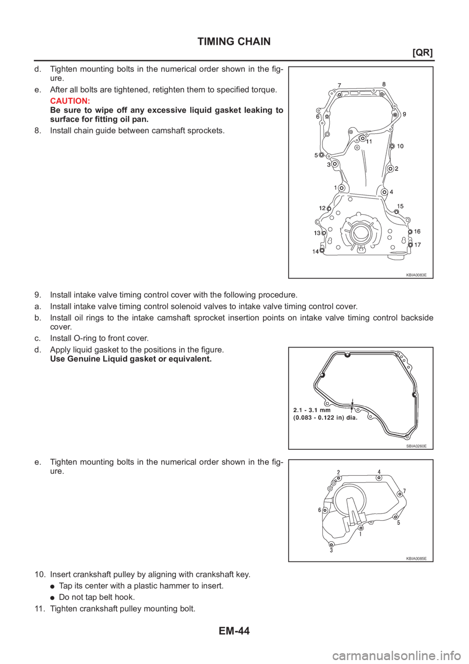
d. Tighten mounting bolts in the numerical order shown in the fig-
ure.
e. After all bolts are tightened, retighten them to specified torque.
CAUTION:
Be sure to wipe off any excessive liquid gasket leaking to
surface for fitting oil pan.
8. Install chain guide between camshaft sprockets.
9. Install intake valve timing control cover with the following procedure.
a. Install intake valve timing control solenoid valves to intake valve timing control cover.
b. Install oil rings to the intake camshaft sprocket insertion points on intake valve timing control backside
cover.
c. Install O-ring to front cover.
d. Apply liquid gasket to the positions in the figure.
Use Genuine Liquid gasket or equivalent.
e. Tighten mounting bolts in the numerical order shown in the fig-
ure.
10. Insert crankshaft pulley by aligning with crankshaft key.
●Tap its center with a plastic hammer to insert.
●Do not tap belt hook.
11. Tighten crankshaft pulley mounting bolt.
KBIA0083E
SBIA0260E
KBIA0085E
Page 100 of 3833
EM-50
[QR]
CAMSHAFT
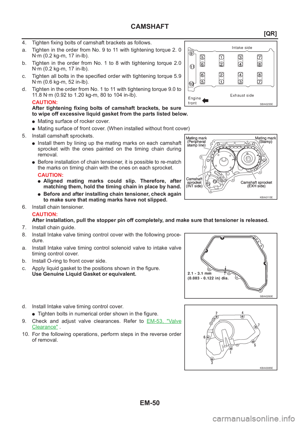
4. Tighten fixing bolts of camshaft brackets as follows.
a. Tighten in the order from No. 9 to 11 with tightening torque 2. 0
N·m (0.2 kg-m, 17 in-lb).
b. Tighten in the order from No. 1 to 8 with tightening torque 2.0
N·m (0.2 kg-m, 17 in-lb).
c. Tighten all bolts in the specified order with tightening torque 5.9
N·m (0.6 kg-m, 52 in-lb).
d. Tighten in the order from No. 1 to 11 with tightening torque 9.0 to
11.8 N·m (0.92 to 1.20 kg-m, 80 to 104 in-lb).
CAUTION:
After tightening fixing bolts of camshaft brackets, be sure
to wipe off excessive liquid gasket from the parts listed below.
●Mating surface of rocker cover.
●Mating surface of front cover. (When installed without front cover)
5. Install camshaft sprockets.
●Install them by lining up the mating marks on each camshaft
sprocket with the ones painted on the timing chain during
removal.
●Before installation of chain tensioner, it is possible to re-match
the marks on timing chain with the ones on each sprocket.
CAUTION:
●Aligned mating marks could slip. Therefore, after
matching them, hold the timing chain in place by hand.
●Before and after installing chain tensioner, check again
to make sure that mating marks have not slipped.
6. Install chain tensioner.
CAUTION:
After installation, pull the stopper pin off completely, and make sure that tensioner is released.
7. Install chain guide.
8. Install Intake valve timing control cover with the following proce-
dure.
a. Install Intake valve timing control solenoid valve to intake valve
timing control cover.
b. Install O-ring to front cover side.
c. Apply liquid gasket to the positions shown in the figure.
Use Genuine Liquid Gasket or equivalent.
d. Install Intake valve timing control cover.
●Tighten bolts in numerical order shown in the figure.
9. Check and adjust valve clearances. Refer to EM-53, "
Va l v e
Clearance" .
10. For the following operations, perform steps in the reverse order
of removal.
SBIA0255E
KBIA0115E
SBIA0260E
KBIA0085E
Page 101 of 3833
CAMSHAFT
EM-51
[QR]
C
D
E
F
G
H
I
J
K
L
MA
EM
INSPECTION AFTER REMOVAL
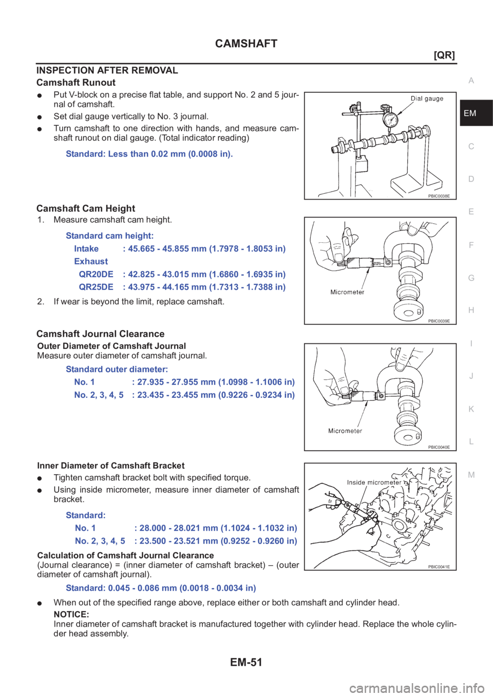
Camshaft Runout
●Put V-block on a precise flat table, and support No. 2 and 5 jour-
nal of camshaft.
●Set dial gauge vertically to No. 3 journal.
●Turn camshaft to one direction with hands, and measure cam-
shaft runout on dial gauge. (Total indicator reading)
Camshaft Cam Height
1. Measure camshaft cam height.
2. If wear is beyond the limit, replace camshaft.
Camshaft Journal Clearance
Outer Diameter of Camshaft Journal
Measure outer diameter of camshaft journal.
Inner Diameter of Camshaft Bracket
●Tighten camshaft bracket bolt with specified torque.
●Using inside micrometer, measure inner diameter of camshaft
bracket.
Calculation of Camshaft Journal Clearance
(Journal clearance) = (inner diameter of camshaft bracket) – (outer
diameter of camshaft journal).
●When out of the specified range above, replace either or both camshaft and cylinder head.
NOTICE:
Inner diameter of camshaft bracket is manufactured together with cylinder head. Replace the whole cylin-
der head assembly.Standard: Less than 0.02 mm (0.0008 in).
PBIC0038E
Standard cam height:
Intake : 45.665 - 45.855 mm (1.7978 - 1.8053 in)
Exhaust
QR20DE : 42.825 - 43.015 mm (1.6860 - 1.6935 in)
QR25DE : 43.975 - 44.165 mm (1.7313 - 1.7388 in)
PBIC0039E
Standard outer diameter:
No. 1 : 27.935 - 27.955 mm (1.0998 - 1.1006 in)
No. 2, 3, 4, 5 : 23.435 - 23.455 mm (0.9226 - 0.9234 in)
PBIC0040E
Standard:
No. 1 : 28.000 - 28.021 mm (1.1024 - 1.1032 in)
No. 2, 3, 4, 5 : 23.500 - 23.521 mm (0.9252 - 0.9260 in)
Standard: 0.045 - 0.086 mm (0.0018 - 0.0034 in)
PBIC0041E
Page 129 of 3833
CYLINDER BLOCK
EM-79
[QR]
C
D
E
F
G
H
I
J
K
L
MA
EM
5. Install the crankshaft to the cylinder block.
●While turning the crankshaft by hand, check that it turns smoothly.
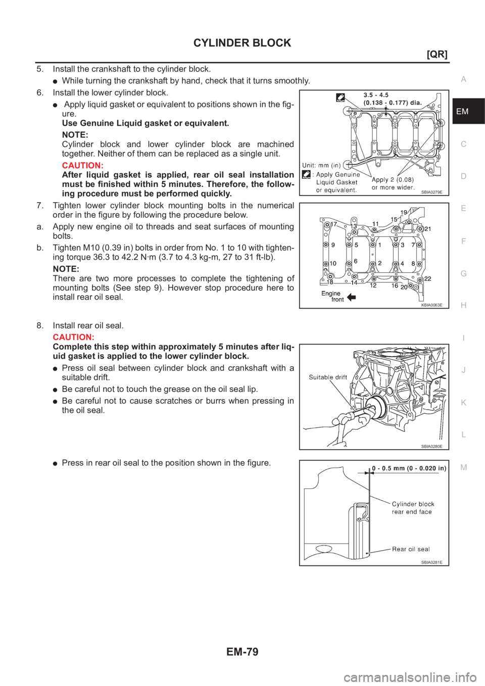
6. Install the lower cylinder block.
● Apply liquid gasket or equivalent to positions shown in the fig-
ure.
Use Genuine Liquid gasket or equivalent.
NOTE:
Cylinder block and lower cylinder block are machined
together. Neither of them can be replaced as a single unit.
CAUTION:
After liquid gasket is applied, rear oil seal installation
must be finished within 5 minutes. Therefore, the follow-
ing procedure must be performed quickly.
7. Tighten lower cylinder block mounting bolts in the numerical
order in the figure by following the procedure below.
a. Apply new engine oil to threads and seat surfaces of mounting
bolts.
b. Tighten M10 (0.39 in) bolts in order from No. 1 to 10 with tighten-
ing torque 36.3 to 42.2 N·m (3.7 to 4.3 kg-m, 27 to 31 ft-lb).
NOTE:
There are two more processes to complete the tightening of
mounting bolts (See step 9). However stop procedure here to
install rear oil seal.
8. Install rear oil seal.
CAUTION:
Complete this step within approximately 5 minutes after liq-
uid gasket is applied to the lower cylinder block.
●Press oil seal between cylinder block and crankshaft with a
suitable drift.
●Be careful not to touch the grease on the oil seal lip.
●Be careful not to cause scratches or burrs when pressing in
the oil seal.
●Press in rear oil seal to the position shown in the figure.
SBIA0279E
KBIA0063E
SBIA0280E
SBIA0281E
Page 141 of 3833
CYLINDER BLOCK
EM-91
[QR]
C
D
E
F
G
H
I
J
K
L
MA
EM
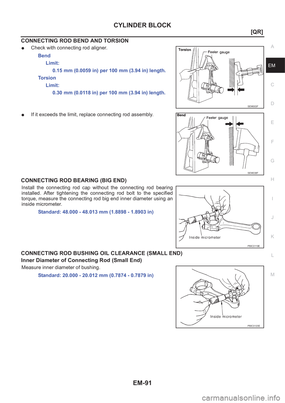
CONNECTING ROD BEND AND TORSION
●Check with connecting rod aligner.
●If it exceeds the limit, replace connecting rod assembly.
CONNECTING ROD BEARING (BIG END)
Install the connecting rod cap without the connecting rod bearing
installed. After tightening the connecting rod bolt to the specified
torque, measure the connecting rod big end inner diameter using an
inside micrometer.
CONNECTING ROD BUSHING OIL CLEARANCE (SMALL END)
Inner Diameter of Connecting Rod (Small End)
Measure inner diameter of bushing.Bend
Limit:
0.15 mm (0.0059 in) per 100 mm (3.94 in) length.
To r s i o n
Limit:
0.30 mm (0.0118 in) per 100 mm (3.94 in) length.
SEM003F
SEM038F
Standard: 48.000 - 48.013 mm (1.8898 - 1.8903 in)
PBIC0119E
Standard: 20.000 - 20.012 mm (0.7874 - 0.7879 in)
PBIC0120E
Page 143 of 3833
CYLINDER BLOCK
EM-93
[QR]
C
D
E
F
G
H
I
J
K
L
MA
EM
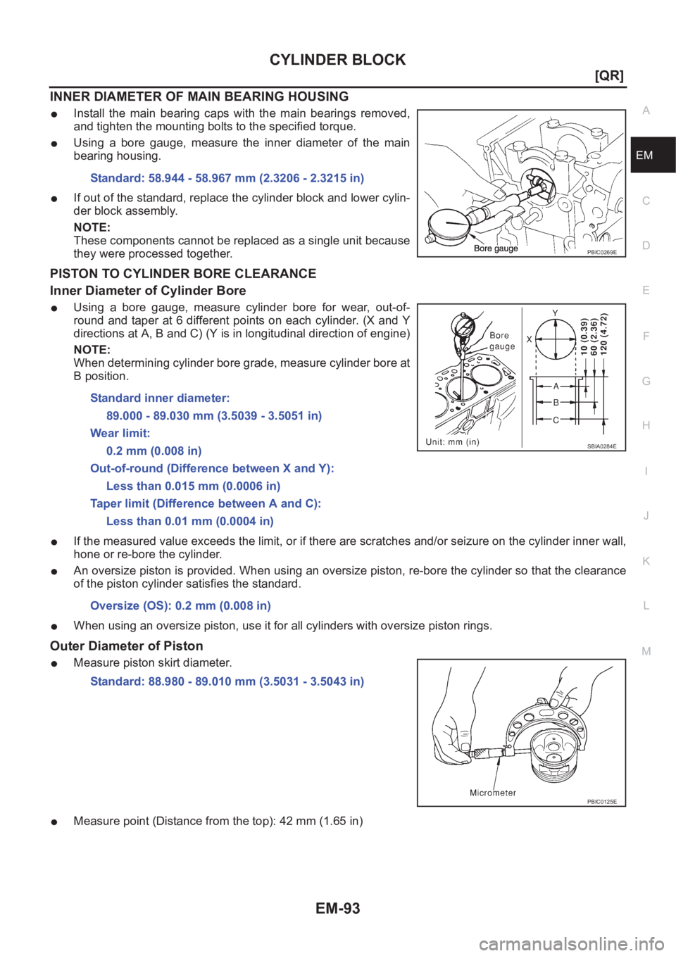
INNER DIAMETER OF MAIN BEARING HOUSING
●Install the main bearing caps with the main bearings removed,
and tighten the mounting bolts to the specified torque.
●Using a bore gauge, measure the inner diameter of the main
bearing housing.
●If out of the standard, replace the cylinder block and lower cylin-
der block assembly.
NOTE:
These components cannot be replaced as a single unit because
they were processed together.
PISTON TO CYLINDER BORE CLEARANCE
Inner Diameter of Cylinder Bore
●Using a bore gauge, measure cylinder bore for wear, out-of-
round and taper at 6 different points on each cylinder. (X and Y
directions at A, B and C) (Y is in longitudinal direction of engine)
NOTE:
When determining cylinder bore grade, measure cylinder bore at
B position.
●If the measured value exceeds the limit, or if there are scratches and/or seizure on the cylinder inner wall,
hone or re-bore the cylinder.
●An oversize piston is provided. When using an oversize piston, re-bore the cylinder so that the clearance
of the piston cylinder satisfies the standard.
●When using an oversize piston, use it for all cylinders with oversize piston rings.
Outer Diameter of Piston
●Measure piston skirt diameter.
●Measure point (Distance from the top): 42 mm (1.65 in)Standard: 58.944 - 58.967 mm (2.3206 - 2.3215 in)
PBIC0269E
Standard inner diameter:
89.000 - 89.030 mm (3.5039 - 3.5051 in)
Wear limit:
0.2 mm (0.008 in)
Out-of-round (Difference between X and Y):
Less than 0.015 mm (0.0006 in)
Taper limit (Difference between A and C):
Less than 0.01 mm (0.0004 in)
Oversize (OS): 0.2 mm (0.008 in)
SBIA0284E
Standard: 88.980 - 89.010 mm (3.5031 - 3.5043 in)
PBIC0125E
Page 144 of 3833
EM-94
[QR]
CYLINDER BLOCK
Piston to Cylinder Bore Clearance
●Calculate by outer diameter of piston skirt and inner diameter of cylinder (direction X, position B).
(Clearance) = (Inner diameter of cylinder) – (Outer diameter of piston skirt).
●If it exceeds the limit, replace piston/piston pin assembly.
Re-boring Cylinder Bore
1. Cylinder bore size is determined by adding piston-to-bore clearance to piston diameter “A”.
2. Install main bearing caps, and tighten to the specified torque. Otherwise, cylinder bores may be distorted
in final assembly.
3. Cut cylinder bores.
●When any cylinder needs boring, all other cylinders must also be bored.
●Do not cut too much out of cylinder bore at a time. Cut only 0.05 mm (0.0020 in) or so in diame-
ter at a time.
4. Hone cylinders to obtain specified piston-to-bore clearance.
5. Measure finished cylinder bore for out-of-round and taper.
●Measurement should be done after cylinder bore cools down.
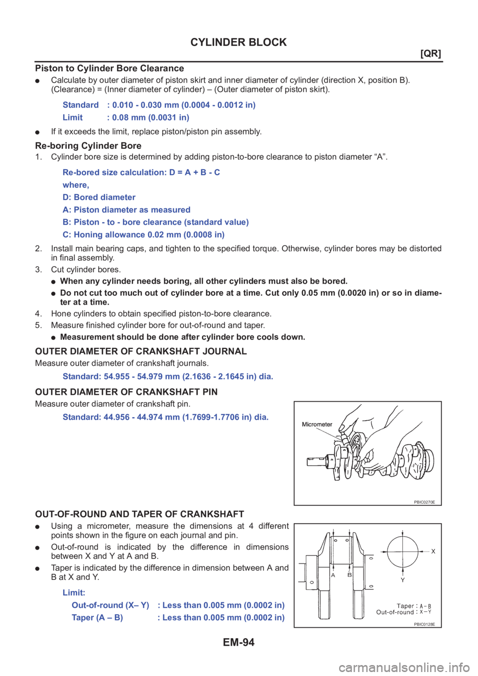
OUTER DIAMETER OF CRANKSHAFT JOURNAL
Measure outer diameter of crankshaft journals.
OUTER DIAMETER OF CRANKSHAFT PIN
Measure outer diameter of crankshaft pin.
OUT-OF-ROUND AND TAPER OF CRANKSHAFT
●Using a micrometer, measure the dimensions at 4 different
points shown in the figure on each journal and pin.
●Out-of-round is indicated by the difference in dimensions
between X and Y at A and B.
●Taper is indicated by the difference in dimension between A and
B at X and Y.Standard : 0.010 - 0.030 mm (0.0004 - 0.0012 in)
Limit : 0.08 mm (0.0031 in)
Re-bored size calculation: D = A + B - C
where,
D: Bored diameter
A: Piston diameter as measured
B: Piston - to - bore clearance (standard value)
C: Honing allowance 0.02 mm (0.0008 in)
Standard: 54.955 - 54.979 mm (2.1636 - 2.1645 in) dia.
Standard: 44.956 - 44.974 mm (1.7699-1.7706 in) dia.
PBIC0270E
Limit:
Out-of-round (X– Y) : Less than 0.005 mm (0.0002 in)
Taper (A – B) : Less than 0.005 mm (0.0002 in)
PBIC0128E