Page 3057 of 3833
HOOD
BL-5
C
D
E
F
G
H
J
K
L
MA
B
BL
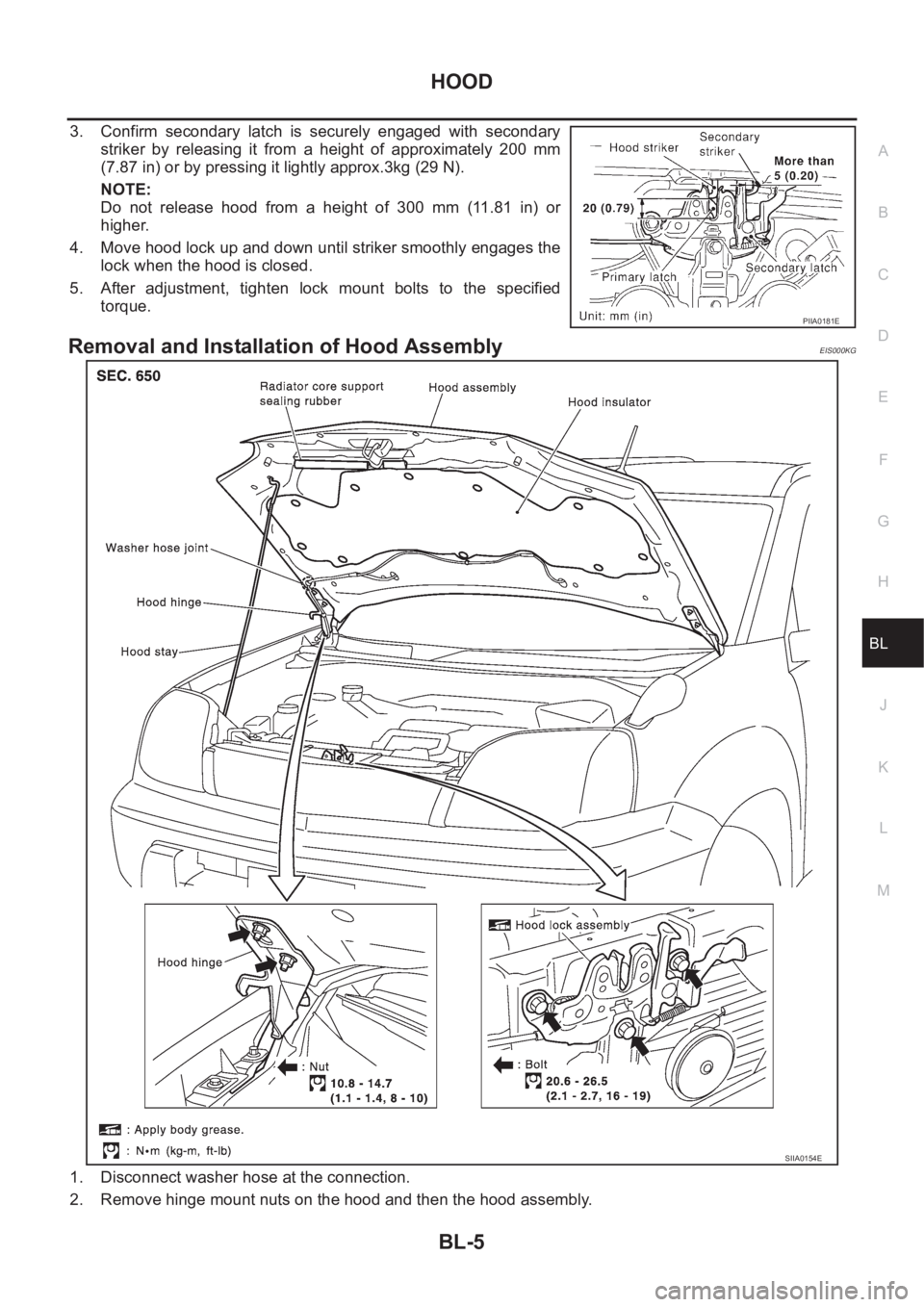
3. Confirm secondary latch is securely engaged with secondary
striker by releasing it from a height of approximately 200 mm
(7.87 in) or by pressing it lightly approx.3kg (29 N).
NOTE:
Do not release hood from a height of 300 mm (11.81 in) or
higher.
4. Move hood lock up and down until striker smoothly engages the
lock when the hood is closed.
5. After adjustment, tighten lock mount bolts to the specified
torque.
Removal and Installation of Hood AssemblyEIS000KG
1. Disconnect washer hose at the connection.
2. Remove hinge mount nuts on the hood and then the hood assembly.
PIIA0181E
SIIA0154E
Page 3059 of 3833
HOOD
BL-7
C
D
E
F
G
H
J
K
L
MA
B
BL
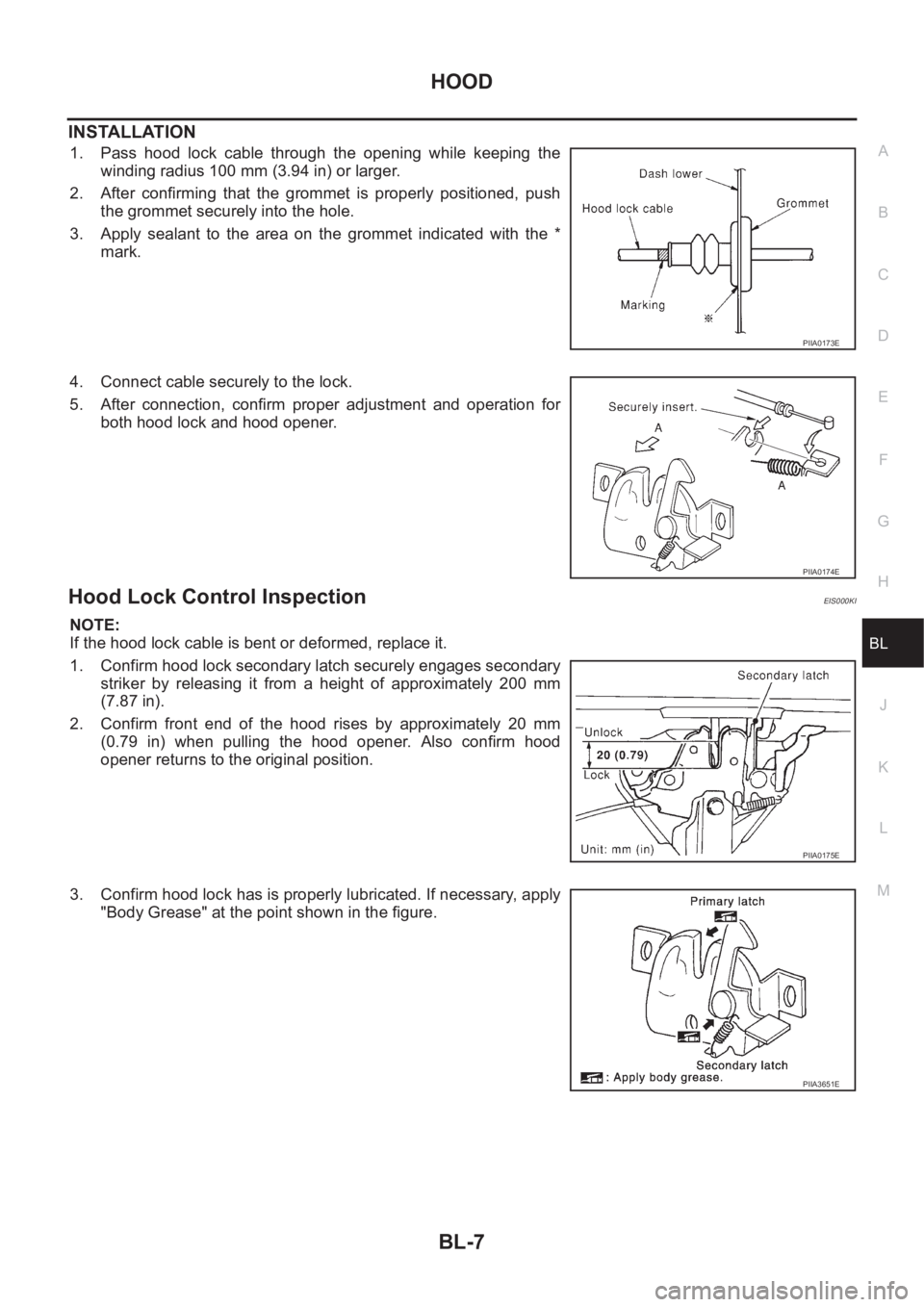
INSTALLATION
1. Pass hood lock cable through the opening while keeping the
winding radius 100 mm (3.94 in) or larger.
2. After confirming that the grommet is properly positioned, push
the grommet securely into the hole.
3. Apply sealant to the area on the grommet indicated with the *
mark.
4. Connect cable securely to the lock.
5. After connection, confirm proper adjustment and operation for
both hood lock and hood opener.
Hood Lock Control InspectionEIS000KI
NOTE:
If the hood lock cable is bent or deformed, replace it.
1. Confirm hood lock secondary latch securely engages secondary
striker by releasing it from a height of approximately 200 mm
(7.87 in).
2. Confirm front end of the hood rises by approximately 20 mm
(0.79 in) when pulling the hood opener. Also confirm hood
opener returns to the original position.
3. Confirm hood lock has is properly lubricated. If necessary, apply
"Body Grease" at the point shown in the figure.
PIIA0173E
PIIA0174E
PIIA0175E
PIIA3651E
Page 3060 of 3833
BL-8
DOOR
DOOR
PFP:80100
Fitting AdjustmentEIS000KJ
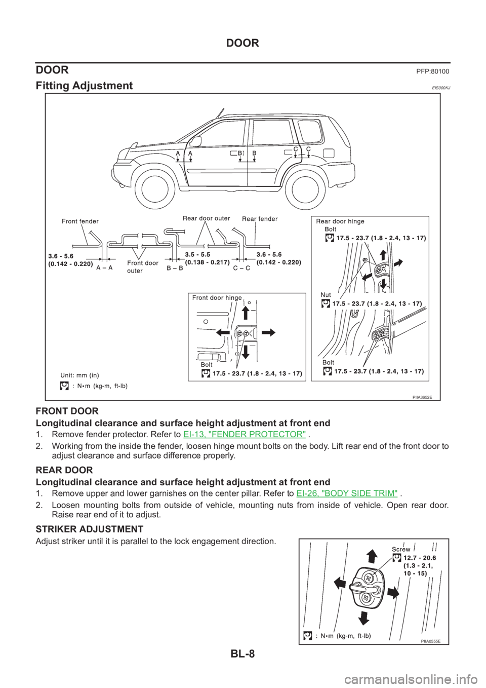
FRONT DOOR
Longitudinal clearance and surface height adjustment at front end
1. Remove fender protector. Refer to EI-13, "FENDER PROTECTOR" .
2. Working from the inside the fender, loosen hinge mount bolts on the body. Lift rear end of the front door to
adjust clearance and surface difference properly.
REAR DOOR
Longitudinal clearance and surface height adjustment at front end
1. Remove upper and lower garnishes on the center pillar. Refer to EI-26, "BODY SIDE TRIM" .
2. Loosen mounting bolts from outside of vehicle, mounting nuts from inside of vehicle. Open rear door.
Raise rear end of it to adjust.
STRIKER ADJUSTMENT
Adjust striker until it is parallel to the lock engagement direction.
PIIA3652E
PIIA0555E
Page 3215 of 3833
SUNROOF
RF-7
C
D
E
F
G
H
J
K
L
MA
B
RF
Fitting AdjustmentEIS000MR
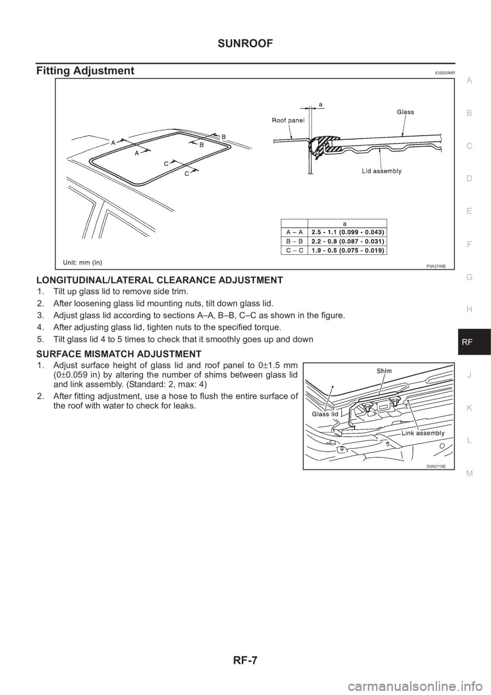
LONGITUDINAL/LATERAL CLEARANCE ADJUSTMENT
1. Tilt up glass lid to remove side trim.
2. After loosening glass lid mounting nuts, tilt down glass lid.
3. Adjust glass lid according to sections A–A, B–B, C–C as shown in the figure.
4. After adjusting glass lid, tighten nuts to the specified torque.
5. Tilt glass lid 4 to 5 times to check that it smoothly goes up and down
SURFACE MISMATCH ADJUSTMENT
1. Adjust surface height of glass lid and roof panel to 0±1.5 mm
(0±0.059 in) by altering the number of shims between glass lid
and link assembly. (Standard: 2, max: 4)
2. After fitting adjustment, use a hose to flush the entire surface of
the roof with water to check for leaks.
PIIA3748E
SIIA0119E
Page 3525 of 3833
FRONT FOG LAMP
LT-35
C
D
E
F
G
H
I
J
L
MA
B
LT
Aiming Adjustment EKS003DH
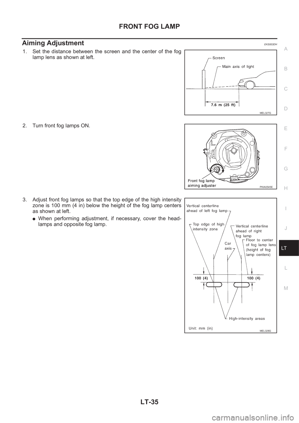
1. Set the distance between the screen and the center of the fog
lamp lens as shown at left.
2. Turn front fog lamps ON.
3. Adjust front fog lamps so that the top edge of the high intensity
zone is 100 mm (4 in) below the height of the fog lamp centers
as shown at left.
●When performing adjustment, if necessary, cover the head-
lamps and opposite fog lamp.
MEL327G
PKIA0545E
MEL328G