2001 NISSAN X-TRAIL change time
[x] Cancel search: change timePage 3568 of 3833
DI-10
COMBINATION METERS (LHD MODELS)
Meter/Gauge Operation and Odo/Trip Meter Segment Check in Diagnosis Mode
EKS002ZC
DIAGNOSIS FUNCTION
●Odo/trip meter segment can be checked in diagnosis mode.
●Meters/gauges can be checked in diagnosis mode.
HOW TO ALTERNATE DIAGNOSIS MODE
1. Turn ignition switch to ON and change odo/trip meter to “TRIP A” or “TRIP B”.
2. Turn ignition switch to OFF.
3. Turn ignition switch to ON when pushing odo/trip meter switch.
4. Confirm that trip meter indicates “000.0”.
5. Push odo/trip meter switch more than three times within 5 seconds.
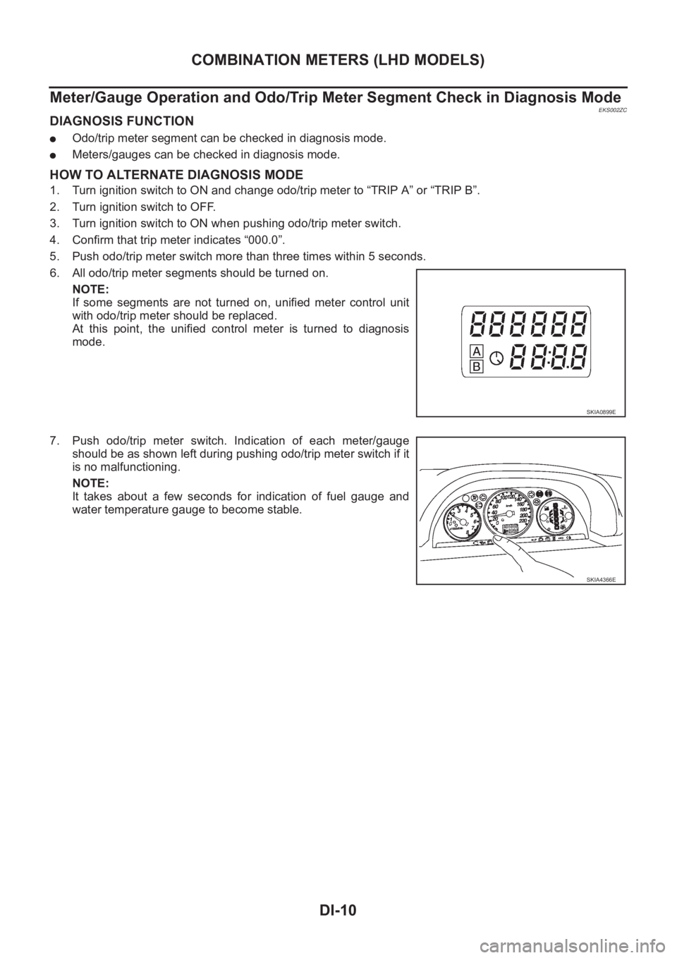
6. All odo/trip meter segments should be turned on.
NOTE:
If some segments are not turned on, unified meter control unit
with odo/trip meter should be replaced.
At this point, the unified control meter is turned to diagnosis
mode.
7. Push odo/trip meter switch. Indication of each meter/gauge
should be as shown left during pushing odo/trip meter switch if it
is no malfunctioning.
NOTE:
It takes about a few seconds for indication of fuel gauge and
water temperature gauge to become stable.
SKIA0899E
SKIA4366E
Page 3582 of 3833
DI-24
COMBINATION METERS (RHD MODELS)
COMBINATION METERS (RHD MODELS)
PFP:24810
System DescriptionEKS0030H
UNIFIED CONTROL METER
●Speedometer, odo/trip meter, tachometer, fuel gauge and water temperature gauge are controlled totally
by control unit built-in combination meter.
●Digital meter is adopted for odo/trip meter.*
*The record of the odo meter is kept even if the battery cable is disconnected. The record of the trip meter
is erased when the battery cable is disconnected.
●Odo/trip meter segment can be checked in diagnosis mode.
●Meter/gauge can be checked in diagnosis mode.
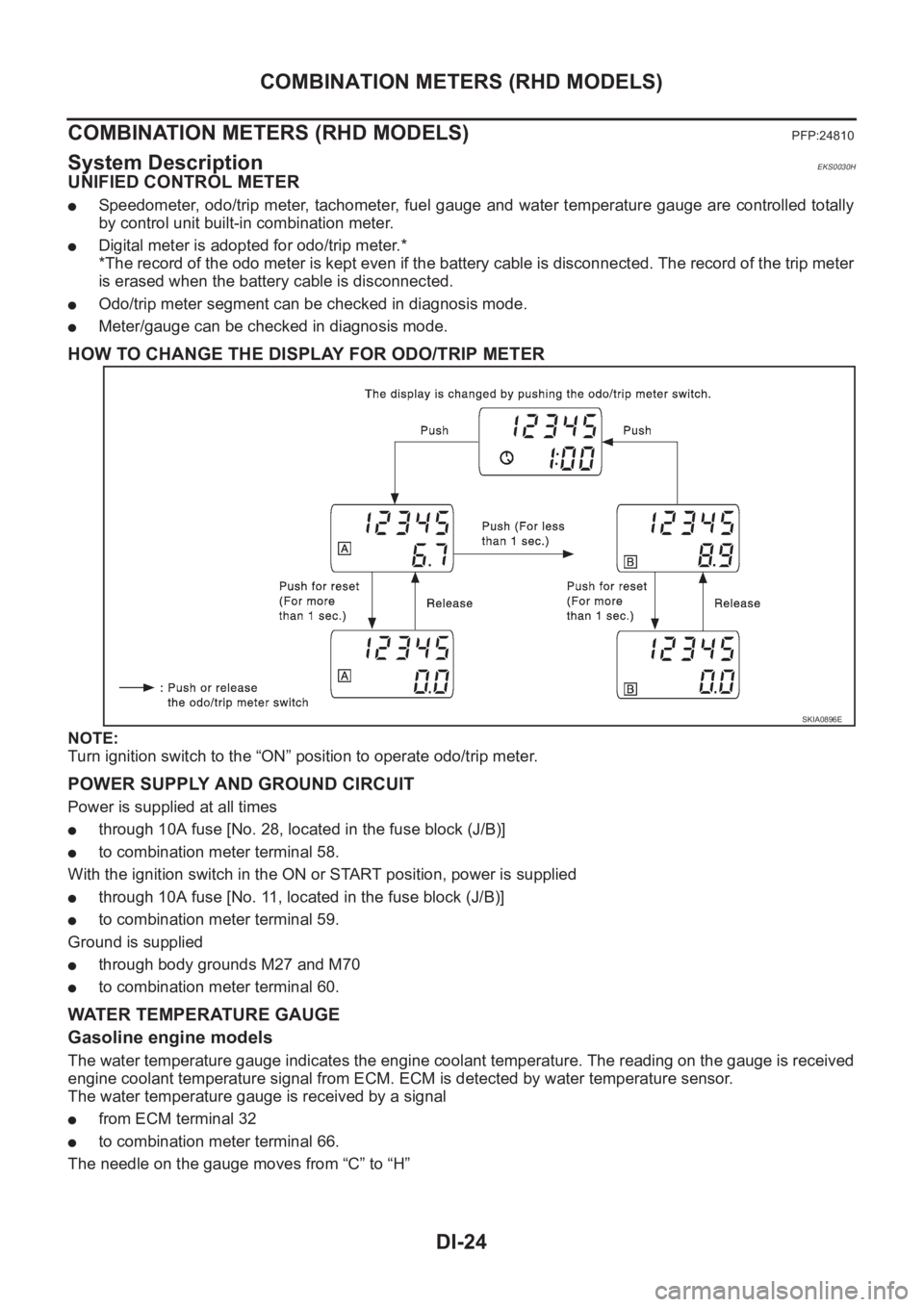
HOW TO CHANGE THE DISPLAY FOR ODO/TRIP METER
NOTE:
Turn ignition switch to the “ON” position to operate odo/trip meter.
POWER SUPPLY AND GROUND CIRCUIT
Power is supplied at all times
●through 10A fuse [No. 28, located in the fuse block (J/B)]
●to combination meter terminal 58.
With the ignition switch in the ON or START position, power is supplied
●through 10A fuse [No. 11, located in the fuse block (J/B)]
●to combination meter terminal 59.
Ground is supplied
●through body grounds M27 and M70
●to combination meter terminal 60.
WATER TEMPERATURE GAUGE
Gasoline engine models
The water temperature gauge indicates the engine coolant temperature. The reading on the gauge is received
engine coolant temperature signal from ECM. ECM is detected by water temperature sensor.
The water temperature gauge is received by a signal
●from ECM terminal 32
●to combination meter terminal 66.
The needle on the gauge moves from “C” to “H”
SKIA0896E
Page 3588 of 3833
DI-30
COMBINATION METERS (RHD MODELS)
Meter/Gauge Operation and Odo/Trip Meter Segment Check in Diagnosis Mode
EKS0030M
DIAGNOSIS FUNCTION
●Odo/trip meter segment can be checked in diagnosis mode.
●Meters/gauges can be checked in diagnosis mode.
HOW TO ALTERNATE DIAGNOSIS MODE
1. Turn ignition switch to ON and change odo/trip meter to “TRIP A” or “TRIP B”.
2. Turn ignition switch to OFF.
3. Turn ignition switch to ON when pushing odo/trip meter switch.
4. Confirm that trip meter indicates “000.0”.
5. Push odo/trip meter switch more than three times within 5 seconds.
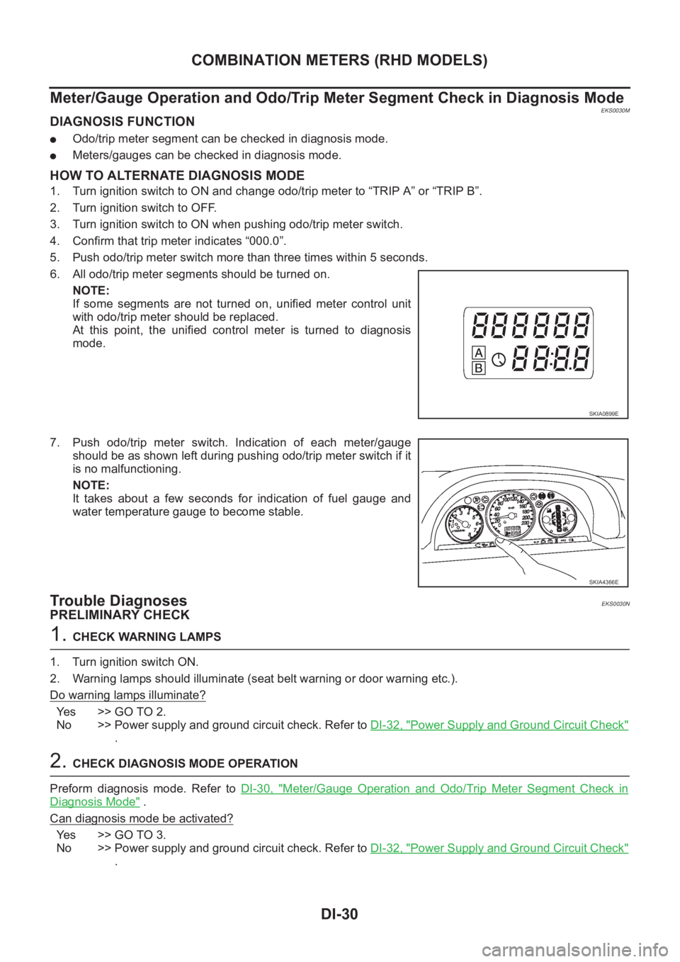
6. All odo/trip meter segments should be turned on.
NOTE:
If some segments are not turned on, unified meter control unit
with odo/trip meter should be replaced.
At this point, the unified control meter is turned to diagnosis
mode.
7. Push odo/trip meter switch. Indication of each meter/gauge
should be as shown left during pushing odo/trip meter switch if it
is no malfunctioning.
NOTE:
It takes about a few seconds for indication of fuel gauge and
water temperature gauge to become stable.
Trouble DiagnosesEKS0030N
PRELIMINARY CHECK
1. CHECK WARNING LAMPS
1. Turn ignition switch ON.
2. Warning lamps should illuminate (seat belt warning or door warning etc.).
Do warning lamps illuminate?
Yes >> GO TO 2.
No >> Power supply and ground circuit check. Refer to DI-32, "
Power Supply and Ground Circuit Check"
.
2. CHECK DIAGNOSIS MODE OPERATION
Preform diagnosis mode. Refer to DI-30, "
Meter/Gauge Operation and Odo/Trip Meter Segment Check in
Diagnosis Mode" .
Can diagnosis mode be activated?
Yes >> GO TO 3.
No >> Power supply and ground circuit check. Refer to DI-32, "
Power Supply and Ground Circuit Check"
.
SKIA0899E
SKIA4366E
Page 3691 of 3833
AUDIO
AV-3
C
D
E
F
G
H
I
J
L
MA
B
AV
AUDIOPFP:28111
System DescriptionEKS002F2
Refer to Owner's Manual for audio system operating instructions.
Power is supplied at all times
●to audio unit terminal 3 and
●to CD auto changer terminal 32
●through 15A fuse (No. 32, located in the fuse and fusible link box).
With the ignition switch in the ACC or ON position, power is supplied
●to audio unit terminal 6 and
●to CD auto changer terminal 36
●through 10A fuse [No. 4, located in the fuse block (J/B)]
Ground is supplied through the case of the audio unit.
Audio signals are supplied
●through audio unit terminals 5, 7, 9, 10, 11, 13, 15, 16
●to terminals 1 and 2 of front door speaker LH and RH,
●to terminals 1 and 2 of rear door speaker LH and RH and
●to terminals 1 and 2 of tweeter LH and RH (with 6-speakers)
NATS AUDIO LINK
Description
The link with the NATS IMMU implies that the audio unit can basically only be operated if connected to the
matching NATS IMMU to which the audio unit was initially fitted on the production line.
Since radio operation is impossible after the link with the NATS is disrupted theft of the audio unit is basically
useless since special equipment is required to reset the audio unit.
Initialization process for audio units that are linked to the NAT S I M M U
New audio units will be delivered to the factories in the “NEW” state, i.e. ready to be linked with the vehicle's
NATS. When the audio unit in “NEW” state is first switched on at the factory, it will start up communication with
the vehicle's immobilizer control unit (IMMU) and send a code (the “audio unit Code”) to the IMMU. The IMMU
will then store this code, which is unique to each audio unit, in its (permanent) memory.
Upon receipt of the code by the IMMU, the NATS will confirm correct receipt of the audio unit code to the audio
unit. Hereafter, the audio unit will operate as normal.
During the initialization process, “NEW” is displayed on the audio unit display. Normally though, communica-
tion between audio unit and IMMU takes such a short time (300 ms) that the audio unit seems to switch on
directly without showing “NEW” on its display.
Normal operation
Each time the audio unit is switched on afterwards, the audio unit code will be verified between the audio unit
and the NATS before the audio unit becomes operational. During the code verification process, “WAIT” is
shown on the audio unit display. Again, the communication takes such a short time (300 ms) that the audio
unit seems to switch on directly without showing “WAIT” on its display.
When the radio is locked
In case of a audio unit being linked with the vehicle's NATS (immobilizer system), disconnection of the link
between the audio unit and the IMMU will cause the audio unit to switch into the lock (“SECURE”) mode in
which the audio unit is fully inoperative. Hence, repair of the audio unit is basically impossible, unless the
audio unit is reset to the “NEW” state for which special decoding equipment is required.
Clarion has provided their authorized service representatives with so called “decoder boxes” which can bring
the audio unit back to the “NEW” state, enabling the audio unit to be switched on after which repair can be car-
ried out. Subsequently, when the repaired audio unit is delivered to the final user again, it will be in the “NEW”
state to enable re-linking the audio unit to the vehicle's immobilizer system. As a result of the above, repair of
the audio unit can only be done by an authorized Clarion representative (when the owner of the vehicle
requests repair and can show personal identification).
Page 3786 of 3833

MA-6
GENERAL MAINTENANCE
GENERAL MAINTENANCE
PFP:00000
General MaintenanceELS000AL
General maintenance includes those items which should be checked during the normal day-to-day operation
of the vehicle. They are essential if the vehicle is to continue operating properly. The owners can perform the
checks and inspections themselves or they can have their NISSAN dealers do them for a nominal charge.
OUTSIDE THE VEHICLE
The maintenance items listed here should be performed from time to time, unless otherwise specified.
INSIDE THE VEHICLE
The maintenance items listed here should be checked on a regular basis, such as when performing periodic maintenance, cleaning the
vehicle, etc.
UNDER THE HOOD AND VEHICLE
The maintenance items listed here should be checked periodically e.g. each time you check the engine oil or refuel. Item Reference page
TiresCheck the pressure with a gauge periodically when at a service station, includ-
ing the spare, and adjust to the specified pressure if necessary. Check carefully
for damage, cuts or excessive wear.—
Windshield wiper
bladesCheck for cracks or wear if not functioning correctly. —
Doors and engine
hoodCheck that all doors, the engine hood, the trunk lid and back door operate prop-
erly. Also ensure that all latches lock securely. Lubricate if necessary. Make sure
that the secondary latch keeps the hood from opening when the primary latch is
released.
When driving in areas using road salt or other corrosive materials, check for
lubrication frequently.BL-4
,BL-8
Tire rotationTires should be rotated every 5,000 km (3,000 miles).MA-38
Item Reference page
LampsMake sure that the headlamps, stop lamps, tail lamps, turn signal lamps, and
other lamps are all operating properly and installed securely. Also check head-
lamp aim.—
Warning lamps and
chimesMake sure that all warning lamps and buzzers/chimes are operating properly. —
Steering wheelCheck that it has the specified play.
Check for changes in the steering conditions, such as excessive free play, hard
steering or strange noises.
Free play: Less than 35 mm (1.38 in)—
Seat beltsCheck that all parts of the seat belt system (e.g. buckles, anchors, a dju sters and
retractors) operate properly and smoothly, and are installed securely. Check the
belt webbing for cuts, fraying, wear or damage.SB-3
Item Reference page
Windshield washer
fluidCheck that there is adequate fluid in the tank. —
Engine coolant levelCheck the coolant level when the engine is cold.CO-29
(QR20DE,
QR25DE)
CO-29
(YD22DDTi)
Engine oil levelCheck the level after parking the vehicle (on level ground) and turning off the
engine.LU-18
(QR20DE,
QR25DE)
LU-18
(YD22DDTi)
Brake and clutch fluid
levelsMake sure that the brake and clutch fluid levels are between the “MAX” and
“MIN” lines on the reservoir.MA-35
,MA-39
BatteryCheck the fluid level in each cell. It should be between the “MAX” and “MIN”
lines.—
Page 3803 of 3833
ENGINE MAINTENANCE (QR20DE·QR25DE)
MA-23
C
D
E
F
G
H
I
J
K
MA
B
MA
Changing Engine OilELS000JZ
WARNING:
●Be careful not to burn yourself, as the engine oil is hot.
●Prolonged and repeated contact with used engine oil may
cause skin cancer. Try to avoid direct skin contact with
used engine oil. If skin contact is made, wash thoroughly
with soap or hand cleaner as soon as possible.
1. Warm up engine, put vehicle horizontally and check for engine
oil leakage from engine components.
2. Stop engine and wait for 10 minutes.
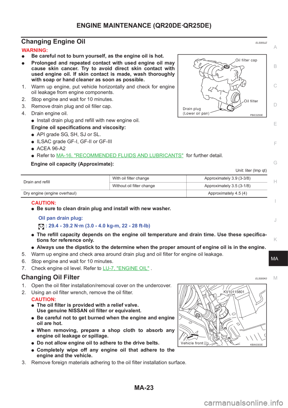
3. Remove drain plug and oil filler cap.
4. Drain engine oil.
●Install drain plug and refill with new engine oil.
Engine oil specifications and viscosity:
●API grade SG, SH, SJ or SL.
●ILSAC grade GF-I, GF-II or GF-III
●ACEA 96-A2
●Refer to MA-16, "RECOMMENDED FLUIDS AND LUBRICANTS" for further detail.
Engine oil capacity (Approximate):
Unit: liter (lmp qt)
CAUTION:
●Be sure to clean drain plug and install with new washer.
●The refill capacity depends on the engine oil temperature and drain time. Use these specifica-
tions for reference only.
●Always use the dipstick to the determine when the proper amount of engine oil is in the engine.
5. Warm up engine and check area around drain plug and oil filter for engine oil leakage.
6. Stop engine and wait for 10 minutes.
7. Check engine oil level. Refer to LU-7, "
ENGINE OIL" .
Changing Oil FilterELS000K0
1. Open the oil filter installation/removal cover on the undercover.
2. Using an oil filter wrench, remove the oil filter.
CAUTION:
●The oil filter is provided with a relief valve.
Use genuine NISSAN oil filter or equivalent.
●Be careful not to get burned when the engine and engine
oil are hot.
●When removing, prepare a shop cloth to absorb any
engine oil leakage or spillage.
●Do not allow engine oil to adhere to the drive belts.
●Completely wipe off any engine oil that adhere to the
engine and the vehicle.
3. Remove foreign materials adhering to the oil filter installation surface.
PBIC0250E
Drain and refillWith oil filter change Approximately 3.9 (3-3/8)
Without oil filter change Approximately 3.5 (3-1/8)
Dry engine (engine overhaul)Approximately 4.5 (4)
Oil pan drain plug:
: 29.4 - 39.2 N·m (3.0 - 4.0 kg-m, 22 - 28 ft-lb)
KBIA0303E
Page 3812 of 3833
MA-32
ENGINE MAINTENANCE (YD22DDTI)
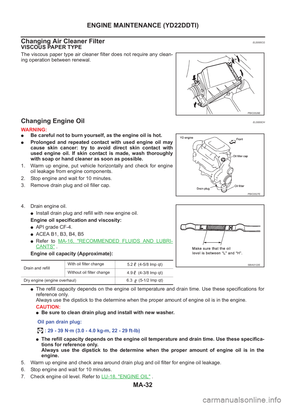
Changing Air Cleaner Filter
ELS000CG
VISCOUS PAPER TYPE
The viscous paper type air cleaner filter does not require any clean-
ing operation between renewal.
Changing Engine OilELS000CH
WARNING:
●Be careful not to burn yourself, as the engine oil is hot.
●Prolonged and repeated contact with used engine oil may
cause skin cancer: try to avoid direct skin contact with
used engine oil. If skin contact is made, wash thoroughly
with soap or hand cleaner as soon as possible.
1. Warm up engine, put vehicle horizontally and check for engine
oil leakage from engine components.
2. Stop engine and wait for 10 minutes.
3. Remove drain plug and oil filler cap.
4. Drain engine oil.
●Install drain plug and refill with new engine oil.
Engine oil specification and viscosity:
●API grade CF-4.
●ACEA B1, B3, B4, B5
●Refer to MA-16, "RECOMMENDED FLUIDS AND LUBRI-
CANTS" .
Engine oil capacity (Approximate):
●The refill capacity depends on the engine oil temperature and drain time. Use these specifications for
reference only.
Always use the dipstick to the determine when the proper amount of engine oil is in the engine.
CAUTION:
●Be sure to clean drain plug and install with new washer.
●The refill capacity depends on the engine oil temperature and drain time. Use these specifica-
tions for reference only.
Always use the dipstick to the determine when the proper amount of engine oil is in the
engine.
5. Warm up engine and check area around drain plug and oil filter for engine oil leakage.
6. Stop engine and wait for 10 minutes.
7. Check engine oil level. Refer to LU-18, "
ENGINE OIL" .
PBIC0526E
PBIC0527E
Drain and refillWith oil filter change
5.2 (4-5/8 Imp qt)
Without oil filter change
4.9 (4-3/8 Imp qt)
Dry engine (engine overhaul)6.3 (5-1/2 Imp qt)
Oil pan drain plug:
: 29 - 39 N·m (3.0 - 4.0 kg-m, 22 - 29 ft-lb)
SBIA0122E