2001 NISSAN QUEST ECO mode
[x] Cancel search: ECO modePage 2 of 304
You will see various symbols in this manual.
They are used in the following ways:
WARNING
This is used to indicate the presence of
a hazard that could cause death or
serious personal injury. To avoid or
reduce the risk, the procedures must
be followed precisely.
CAUTION
This is used to indicate the presence of
a hazard that could cause minor or
moderate personal injury or damage to
your vehicle. To avoid or reduce the
risk, the procedures must be followed
carefully.If you see this symbol, it means ``Do not do
this'' or ``Do not let this happen.''
CALIFORNIA PROPOSITION 65
WARNING
WARNING
Engine Exhaust, some of its constitu-
ents, and certain vehicle components
contain or emit chemicals known to
State of California to cause cancer and
birth defects or other reproductive
harm.
2001 NISSAN NORTH AMERICA, INC.
GARDENA, CALIFORNIA
All rights reserved. No part of this Owner's
Manual may be reproduced or stored in a
retrieval system, or transmitted in any form, or
by any means, electronic, mechanical, photo-
copying, recording or otherwise, without the
prior written permission of Nissan North
America, Inc., Gardena, California
The inside pages of this manual contain
a minimum of 50% recycled fibers,
including 10% post-consumer fibers.
APD1005
IMPORTANT INFORMATION
ABOUT THIS MANUAL
ZX
Page 66 of 304
INSTALLATION ON SECOND
AND THIRD ROW OUTBOARD
POSITIONS
Front facing
The following instructions apply to second
row bucket seats, the second row bench
seat and the outboard positions of the three-
passenger bench seat.
WARNING
When installing a child restraint in the
two-passenger bench seat, if it is
placed in the seating position next to
the passenger side sliding door, be
sure both the auxiliary buckle and main
buckle are properly fastened. Failure to
do so could increase the chance and/or
severity of injury in an accident.
WARNING
cThe three-point belt in your vehicle
is equipped with locking mode re-
tractor which must be used when
installing a child restraint.
cFailure to use the retractor's locking
mode will result in the child restraint
not being properly secured. The re-
straint could tip over or otherwise be
unsecured and cause injury to the
child in a sudden stop or collision.
When you install a child restraint in a sec-
ond row bucket seat, the second row bench
seat or the outboard positions of the three-
passenger bench seat follow these steps:
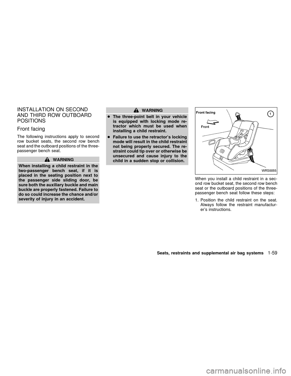
1. Position the child restraint on the seat.
Always follow the restraint manufactur-
er's instructions.
WRS0055
Seats, restraints and supplemental air bag systems1-59
ZX
Page 68 of 304
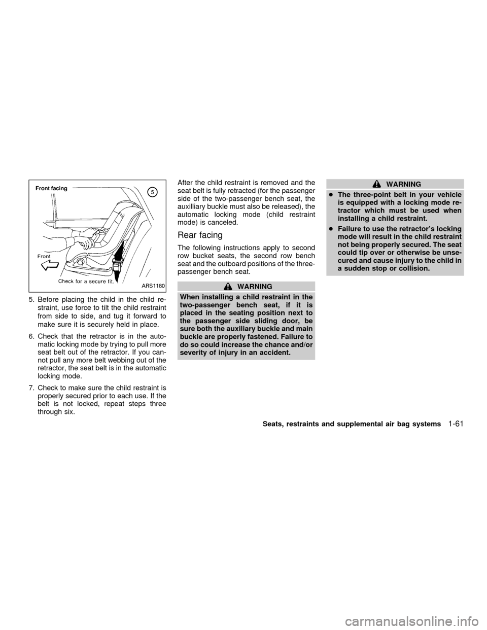
5. Before placing the child in the child re-
straint, use force to tilt the child restraint
from side to side, and tug it forward to
make sure it is securely held in place.
6. Check that the retractor is in the auto-
matic locking mode by trying to pull more
seat belt out of the retractor. If you can-
not pull any more belt webbing out of the
retractor, the seat belt is in the automatic
locking mode.
7. Check to make sure the child restraint is
properly secured prior to each use. If the
belt is not locked, repeat steps three
through six.After the child restraint is removed and the
seat belt is fully retracted (for the passenger
side of the two-passenger bench seat, the
auxilliary buckle must also be released), the
automatic locking mode (child restraint
mode) is canceled.
Rear facing
The following instructions apply to second
row bucket seats, the second row bench
seat and the outboard positions of the three-
passenger bench seat.
WARNING
When installing a child restraint in the
two-passenger bench seat, if it is
placed in the seating position next to
the passenger side sliding door, be
sure both the auxiliary buckle and main
buckle are properly fastened. Failure to
do so could increase the chance and/or
severity of injury in an accident.
WARNING
cThe three-point belt in your vehicle
is equipped with a locking mode re-
tractor which must be used when
installing a child restraint.
cFailure to use the retractor's locking
mode will result in the child restraint
not being properly secured. The seat
could tip over or otherwise be unse-
cured and cause injury to the child in
a sudden stop or collision.
ARS1180
Seats, restraints and supplemental air bag systems1-61
ZX
Page 71 of 304
INSTALLATION ON FRONT
PASSENGER SEAT
WARNING
c
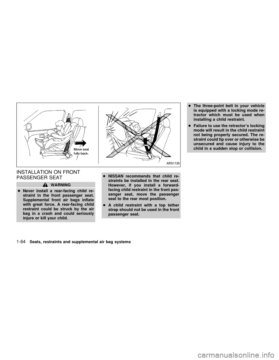
Never install a rear-facing child re-
straint in the front passenger seat.
Supplemental front air bags inflate
with great force. A rear-facing child
restraint could be struck by the air
bag in a crash and could seriously
injure or kill your child.cNISSAN recommends that child re-
straints be installed in the rear seat.
However, if you install a forward-
facing child restraint in the front pas-
senger seat, move the passenger
seat to the rear most position.
cA child restraint with a top tether
strap should not be used in the front
passenger seat.cThe three-point belt in your vehicle
is equipped with a locking mode re-
tractor which must be used when
installing a child restraint.
cFailure to use the retractor's locking
mode will result in the child restraint
not being properly secured. The re-
straint could tip over or otherwise be
unsecured and cause injury to the
child in a sudden stop or collision.
ARS1135
1-64Seats, restraints and supplemental air bag systems
ZX
Page 86 of 304
shoulder harness retractor is in the emer-
gency locking mode.
WARNING
The automatic locking mode (child re-
straint mode) must be reactivated each
time you place a child in the integrated
child safety seats.
In addition to the automatic locking retrac-
tors, the integrated child safety seat shoul-
der harnesses are equipped with emer-
gency locking retractors. The automatic
locking mode is best to use, especially for
children who need help staying properly
positioned in the seat and its harnesses (for
example, children who are younger and
smaller), because the belts are always
locked. In the emergency locking mode, the
shoulder belts only lock in a sudden stop or
accident, allowing a child more freedom of
movement. Use the emergency locking
mode only if you judge your child able to
remain properly positioned in the integrated
child safety seat.
Removing the child
1. Release the chest clip.
2. Release the left and right shoulder har-ness tongues from the belt buckle by
pressing the red belt buckle button.
3. Move the left and right shoulder har-
nesses aside and assist the child from
the integrated child safety seat.
Storing the Integrated Child Safety
Seat
1. Be sure the shoulder harnesses are fully
retracted and resting inside the inte-
grated child safety seat recess. It is not
necessary to reconnect the shoulder har-
nesses and belt buckle prior to storing
the integrated child safety seat.
2. While holding onto, but not pulling, the
cushion release strap, rotate the cushion
upward until it fits flush with the second
row seat back cushion and locks into
position.
3. Be sure the integrated child safety seat is
locked in the stowed position by grasping
the safety seat cushion and attempting to
lower it without pulling the cushion re-
lease strap. If the integrated child safety
seat is not locked in the stowed position,
repeat steps one through three.
Integrated Child Safety Seat main-
tenance
cTo clean the shoulder harnesses and belt
buckle webbing, apply a mild soap solu-
tion or any solution recommended for
cleaning upholstery or carpets. Then
brush the webbing, wipe it with a cloth
and allow it to dry in the shade. Do not
allow the shoulder harnesses to retract
until they are completely dry.
cThe integrated child safety seats cloth
removable pads may be cleaned with
mild soap and water. The cloth remov-
able pads are attached to the seats with
fastener strips, and may be easily re-
moved. The pads are machine washable.
Fo best results, machine wash in cold
water in the gentle cycle. Tumble dry on
low heat. Do not use chlorine bleach, and
do not dry clean.
CAUTION
Failure to follow the washing instruc-
tions provided on the cloth removable
pads may result in premature wear or
damage.
Seats, restraints and supplemental air bag systems
1-79
ZX
Page 98 of 304
applied, stop the vehicle and perform the
following:
1.
Check the brake fluid level. Add brake fluid
as necessary. See ``Brake fluid'' in the
``Do-it-yourself'' section of this manual.
2. If the brake fluid level is correct, have the
warning system checked by an autho-
rized NISSAN dealer.
WARNING
cYour brake system may not be work-
ing properly if the warning light is
on. Driving could be dangerous. If
you judge it to be safe, drive care-
fully to the nearest service station
for repairs. Otherwise, have your ve-
hicle towed because driving it could
be dangerous.
cPressing the brake pedal with the
engine stopped and/or low brake
fluid level may increase your stop-
ping distance and braking will re-
quire greater pedal effort as well as
pedal travel.
cIf the brake fluid level is below the
MINIMUM or MIN mark on the brakefluid reservoir, do not drive until the
brake system has been checked at a
NISSAN dealer.
Anti-lock brake warning light
If the light comes on while the engine is
running, it may indicate the anti-lock portion
of the brake system is not functioning prop-
erly. Have the system checked by an autho-
rized NISSAN dealer.
If a malfunction occurs in the system, the
anti-lock function turns off, but the brakes
continue to operate normally.
If the light comes on while you are driv-
ing, contact an authorized NISSAN
dealer for repair.
Low fuel warning light
This light comes on when the fuel level in
the fuel tank is getting low. Refuel as soon
as it is convenient, preferably before the fuel
gauge reaches E (Empty).There will be a
small reserve of fuel in the tank when the
fuel gauge needle reaches E (Empty).
INDICATOR LIGHTS
Overdrive off indicator light
This light comes on during driving when the
overdrive switch is pressed to prevent over-
drive operation.
The O/D OFF indicator light comes on for
two seconds each time the ignition key is
turned ON. This shows the light is function-
ing properly.
If the O/D OFF indicator light blinks for
approximately 8 seconds after coming on for
2 seconds, have an authorized NISSAN
dealer check the transmission and repair it if
necessary.
The automatic transmission is equipped
with an electronic Fail-Safe mode. This sys-
tem allows the vehicle to be driven even in
the event of damage to the electrical cir-
cuits. If this occurs, the gears automatically
engage and lock into third gear.
NOTE: See ``Fail-safe'' in the ``Starting and
driving'' section of this manual before visit-
ing an authorized NISSAN dealer.
Instruments and controls
2-9
ZX
Page 123 of 304
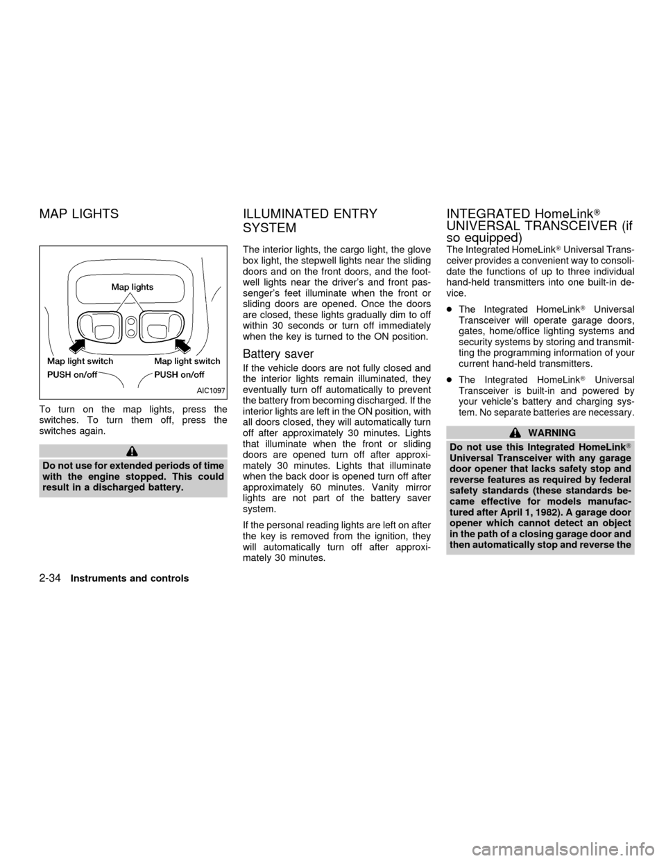
To turn on the map lights, press the
switches. To turn them off, press the
switches again.
Do not use for extended periods of time
with the engine stopped. This could
result in a discharged battery.The interior lights, the cargo light, the glove
box light, the stepwell lights near the sliding
doors and on the front doors, and the foot-
well lights near the driver's and front pas-
senger's feet illuminate when the front or
sliding doors are opened. Once the doors
are closed, these lights gradually dim to off
within 30 seconds or turn off immediately
when the key is turned to the ON position.
Battery saver
If the vehicle doors are not fully closed and
the interior lights remain illuminated, they
eventually turn off automatically to prevent
the battery from becoming discharged. If the
interior lights are left in the ON position, with
all doors closed, they will automatically turn
off after approximately 30 minutes. Lights
that illuminate when the front or sliding
doors are opened turn off after approxi-
mately 30 minutes. Lights that illuminate
when the back door is opened turn off after
approximately 60 minutes. Vanity mirror
lights are not part of the battery saver
system.
If the personal reading lights are left on after
the key is removed from the ignition, they
will automatically turn off after approxi-
mately 30 minutes.The Integrated HomeLinkTUniversal Trans-
ceiver provides a convenient way to consoli-
date the functions of up to three individual
hand-held transmitters into one built-in de-
vice.
cThe Integrated HomeLinkTUniversal
Transceiver will operate garage doors,
gates, home/office lighting systems and
security systems by storing and transmit-
ting the programming information of your
current hand-held transmitters.
c
The Integrated HomeLinkTUniversal
Transceiver is built-in and powered by
your vehicle's battery and charging sys-
tem. No separate batteries are necessary.
WARNING
Do not use this Integrated HomeLinkT
Universal Transceiver with any garage
door opener that lacks safety stop and
reverse features as required by federal
safety standards (these standards be-
came effective for models manufac-
tured after April 1, 1982). A garage door
opener which cannot detect an object
in the path of a closing garage door and
then automatically stop and reverse the
AIC1097
MAP LIGHTS ILLUMINATED ENTRY
SYSTEMINTEGRATED HomeLinkT
UNIVERSAL TRANSCEIVER (if
so equipped)
2-34Instruments and controls
ZX
Page 125 of 304

5. Press the desired button until the red
indicator light flashes slowly. Do not re-
lease the button. Continue holding and
press the hand-held transmitter button
through step 6.
6. Hold down both buttons until the red
indicator light on the Integrated
HomeLinkTUniversal Transceiver
flashes rapidly (This may take 1 to 90
seconds). Then release both buttons.
The rapid flashing means that the trans-
ceiver has been successfully pro-
grammed to match your hand-held trans-
mitter. You can now use the Integrated
HomeLinkTUniversal Transceiver in-
stead of your hand-held transmitter.
PROGRAMMING HomelinkTFOR
CANADIAN CUSTOMERS
Prior to 1992, D.O.C. regulations required
many hand-held transmitters to stop trans-
mitting after one or two seconds, even
though you continue to hold down the but-
ton. If you think you have one of these
hand-held transmitters, you should press
and re-press the transmitter button every 2
seconds without ever releasing the Inte-
grated HomeLinkTUniversal Transceiver
button. The indicator light on the IntegratedHomeLinkTUniversal Transceiver should
blink rapidly indicating a successful pro-
gramming procedure. If it returns to the slow
blink of program mode, continue to periodi-
cally reactivate your hand-held transmitter
until a successful programming procedure
is indicated by the rapidly flashing indicator
light.
OPERATING THE INTEGRATED
HomeLinkTUNIVERSAL TRANS-
CEIVER
To operate, simply press the appropriate
button on the Integrated HomeLinkTUniver-
sal Transceiver. The red indicator light illu-
minates while the signal is being transmit-
ted. The effective transmission range of the
Integrated HomeLinkTUniversal Trans-
ceiver may differ from your hand-held trans-
mitter.
PROGRAMMING TROUBLE
DIAGNOSIS
Be sure to keep your original hand-held
transmitter for possible reprogramming if
necessary.
cMake sure batteries in the hand-held
transmitter are fully charged.cHold your hand-held transmitter against
the bottom surface of the Integrated
HomeLinkTUniversal Transceiver so
that you can still see the red indicator
light.
cHold buttons for duration of the program-
ming without interruption.
cRotate your hand-held transmitter end-
over-end and program again. For best
results, place the end opposite the bat-
tery compartment against the Integrated
HomeLinkTUniversal Transceiver when
programming.
2-36Instruments and controls
ZX