Page 21 of 273
TBR024M
TROUBLE DIAGNOSES
Wiring Diagram Ð ABS Ð (Cont'd)
BR-2005
Page 22 of 273
TBR025M
TROUBLE DIAGNOSES
Wiring Diagram Ð ABS Ð (Cont'd)
BR-2006
Page 23 of 273
TBR026M
TROUBLE DIAGNOSES
Wiring Diagram Ð ABS Ð (Cont'd)
BR-2007
Page 24 of 273
TBR027M
TROUBLE DIAGNOSES
Wiring Diagram Ð ABS Ð (Cont'd)
BR-2008
Page 25 of 273
BODY & TRIM
SECTION
BT
MODIFICATION NOTICE:
+Front grille and bumper assembly have been changed.
+Front grille guard has been added.
CONTENTS
PRECAUTIONS................................................... 2002
Service Notice .................................................. 2002
Supplemental Restraint System (SRS) ªAIR
BAGº and ªSEAT BELT PRE-TENSIONERº ... 2002BODY END.......................................................... 2003
Body Front End ................................................ 2003
EXTERIOR........................................................... 2006
HFor seat belt, refer to MA and RS section.
HFor wiring diagrams of body electrical systems, refer to EL section.
BT
Page 38 of 273

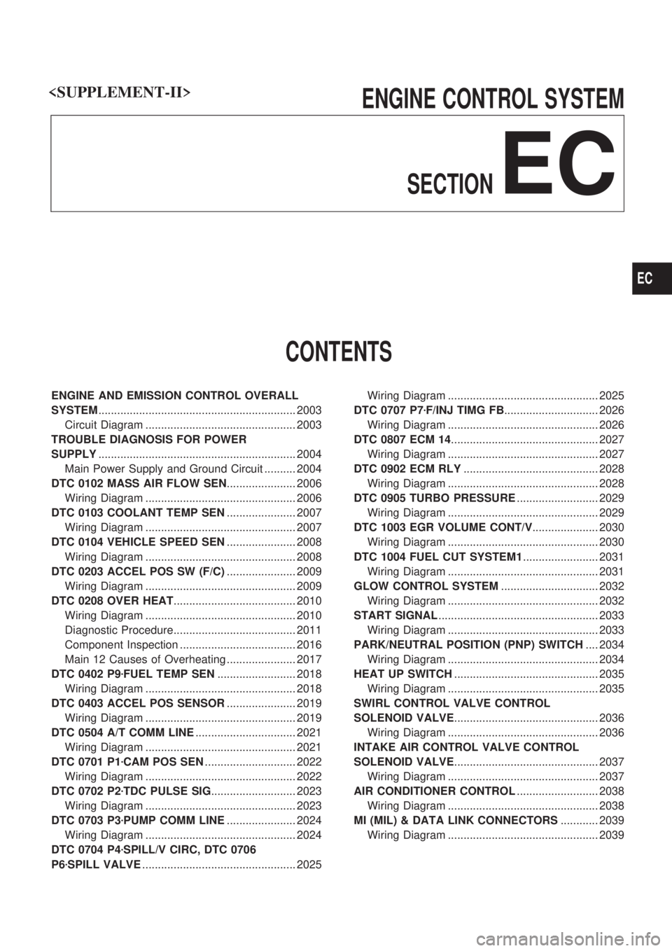
ENGINE CONTROL SYSTEM
SECTION
EC
CONTENTS
ENGINE AND EMISSION CONTROL OVERALL
SYSTEM............................................................... 2003
Circuit Diagram ................................................ 2003
TROUBLE DIAGNOSIS FOR POWER
SUPPLY............................................................... 2004
Main Power Supply and Ground Circuit .......... 2004
DTC 0102 MASS AIR FLOW SEN...................... 2006
Wiring Diagram ................................................ 2006
DTC 0103 COOLANT TEMP SEN...................... 2007
Wiring Diagram ................................................ 2007
DTC 0104 VEHICLE SPEED SEN...................... 2008
Wiring Diagram ................................................ 2008
DTC 0203 ACCEL POS SW (F/C)...................... 2009
Wiring Diagram ................................................ 2009
DTC 0208 OVER HEAT....................................... 2010
Wiring Diagram ................................................ 2010
Diagnostic Procedure....................................... 2011
Component Inspection ..................................... 2016
Main 12 Causes of Overheating ...................... 2017
DTC 0402 P9zFUEL TEMP SEN......................... 2018
Wiring Diagram ................................................ 2018
DTC 0403 ACCEL POS SENSOR...................... 2019
Wiring Diagram ................................................ 2019
DTC 0504 A/T COMM LINE................................ 2021
Wiring Diagram ................................................ 2021
DTC 0701 P1zCAM POS SEN............................. 2022
Wiring Diagram ................................................ 2022
DTC 0702 P2zTDC PULSE SIG........................... 2023
Wiring Diagram ................................................ 2023
DTC 0703 P3zPUMP COMM LINE...................... 2024
Wiring Diagram ................................................ 2024
DTC 0704 P4zSPILL/V CIRC, DTC 0706
P6zSPILL VALVE................................................. 2025Wiring Diagram ................................................ 2025
DTC 0707 P7zF/INJ TIMG FB.............................. 2026
Wiring Diagram ................................................ 2026
DTC 0807 ECM 14............................................... 2027
Wiring Diagram ................................................ 2027
DTC 0902 ECM RLY........................................... 2028
Wiring Diagram ................................................ 2028
DTC 0905 TURBO PRESSURE.......................... 2029
Wiring Diagram ................................................ 2029
DTC 1003 EGR VOLUME CONT/V..................... 2030
Wiring Diagram ................................................ 2030
DTC 1004 FUEL CUT SYSTEM1........................ 2031
Wiring Diagram ................................................ 2031
GLOW CONTROL SYSTEM............................... 2032
Wiring Diagram ................................................ 2032
START SIGNAL................................................... 2033
Wiring Diagram ................................................ 2033
PARK/NEUTRAL POSITION (PNP) SWITCH.... 2034
Wiring Diagram ................................................ 2034
HEAT UP SWITCH.............................................. 2035
Wiring Diagram ................................................ 2035
SWIRL CONTROL VALVE CONTROL
SOLENOID VALVE.............................................. 2036
Wiring Diagram ................................................ 2036
INTAKE AIR CONTROL VALVE CONTROL
SOLENOID VALVE.............................................. 2037
Wiring Diagram ................................................ 2037
AIR CONDITIONER CONTROL.......................... 2038
Wiring Diagram ................................................ 2038
MI (MIL) & DATA LINK CONNECTORS............ 2039
Wiring Diagram ................................................ 2039
EC
Page 39 of 273
When you read wiring diagrams:
+Read GI section, ªHOW TO READ WIRING DIAGRAMSº.
+See EL section, ªPOWER SUPPLY ROUTINGº for power distribution circuit.
When you perform trouble diagnoses, read GI section, ªHOW TO FOLLOW FLOW CHART IN
TROUBLE DIAGNOSESº and ªHOW TO PERFORM EFFICIENT DIAGNOSIS FOR AN ELECTRICAL
INCIDENTº.
EC-2002
Page 40 of 273
Circuit Diagram
TEC095M
ENGINE AND EMISSION CONTROL OVERALL SYSTEM
EC-2003