2001 NISSAN PATROL ignition
[x] Cancel search: ignitionPage 209 of 273
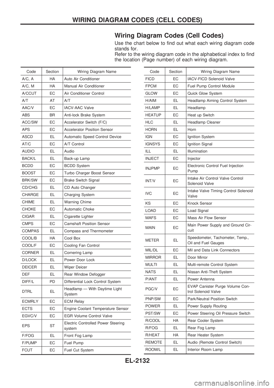
Wiring Diagram Codes (Cell Codes)
Use the chart below to find out what each wiring diagram code
stands for.
Refer to the wiring diagram code in the alphabetical index to find
the location (Page number) of each wiring diagram.
Code Section Wiring Diagram Name
A/C, A HA Auto Air Conditioner
A/C, M HA Manual Air Conditioner
A/CCUT EC Air Conditioner Control
A/T AT A/T
AAC/V EC IACV-AAC Valve
ABS BR Anti-lock Brake System
ACC/SW EC Accelerator Switch (F/C)
APS EC Accelerator Position Sensor
ASCD EL Automatic Speed Control Device
AT/C EC A/T Control
AUDIO EL Audio
BACK/L EL Back-up Lamp
BCDD EC BCDD System
BOOST EC Turbo Charger Boost Sensor
BRK/SW EC Brake Switch Signal
CD/CHG EL CD Auto Changer
CHARGE EL Charging System
CHIME EL Warning Chime
CHOKE EC Automatic Choke
CIGAR EL Cigarette Lighter
CMPS EC Camshaft Position Sensor
COMPAS EL Compass and Thermometer
COOL/B HA Cool Box
COOL/F EC Cooling Fan Control
CORNER EL Cornering Lamp
D/LOCK EL Power Door Lock
DEICER EL Wiper Deicer
DEF EL Rear Window Defogger
DIFF/L PD Differential Lock Control System
DTRL ELHeadlamp Ð With Daytime Light
System
ECMRLY EC ECM Relay
ECTS EC Engine Coolant Temperature Sensor
EGVC/V EC EGR Volume Control Valve
EPS STElectric Controlled Power Steering
system
F/FOG EL Front Fog Lamp
F/PUMP EC Fuel Pump
FCUT EC Fuel Cut SystemCode Section Wiring Diagram Name
FICD EC IACV-FICD Solenoid Valve
FPCM EC Fuel Pump Control Module
GLOW EC Quick Glow System
H/AIM EL Headlamp Aiming Control System
H/LAMP EL Headlamp
HEATUP EC Heat up Switch
HLC EL Headlamp Cleaner
HORN EL Horn
IGN EC Ignition System
IGNSYS EC Ignition Signal
ILL EL Illumination
INJECT EC Injector
INJPMP ECElectronic Control Fuel Injection
Pump
INT/V ECIntake Air Control Valve Control
Solenoid Valve
IVC ECIntake Valve Timing Control Solenoid
Valve
KS EC Knock Sensor
LOAD EC Load Signal
MAFS EC Mass Air Flow Sensor
MAIN ECMain Power Supply and Ground Cir-
cuit
METER ELSpeedometer, Tachometer, Temp.,
Oil and Fuel Gauges
MIL/DL EC Mil and Data Link Connectors
MIRROR EL Door Mirror
MULTI EL Multi-remote Control System
NATS EL Nissan Anti-Theft System
P/ANT EL Power Antenna
PGC/V ECEVAP Canister Purge Volume Con-
trol Solenoid Valve
PNP/SW EC Park/Neutral Position Switch
POWER EL Power Supply Routing
PST/SW EC Power Steering Oil Pressure Switch
R/COOL HA Rear Cooler System
R/FOG EL Rear Fog Lamp
R/HEAT HA Rear Heater System
REMOTE EL Audio (Remote Control Switch)
ROOM/L EL Interior Room Lamp
WIRING DIAGRAM CODES (CELL CODES)
EL-2132
Page 254 of 273
Precautions for SRS ªAIR BAGº and ªSEAT
BELT PRE-TENSIONERº Service
+Do not use electrical test equipment to check SRS circuits unless instructed to in this Service Manual.
+Before servicing the SRS, turn ignition switch ªOFFº, disconnect both battery cables and wait at least 3
minutes.
For approximately 3 minutes after the cables are removed, it is still possible for the air bag and seat belt
pre-tensioner to deploy. Therefore, do not work on any SRS connectors or wires until at least 3 minutes
have passed.
+Diagnosis sensor unit must always be installed with their arrow marks ª
Sº pointing towards the front of
the vehicle for proper operation. Also check diagnosis sensor unit for cracks, deformities or rust before
installation and replace as required.
+The spiral cable must be aligned with the neutral position since its rotations are limited. Do not attempt
to turn steering wheel or column after removal of steering gear.
+Handle air bag module carefully. Always place driver and passenger air bag modules with the pad side
facing upward and front side air bag modules (built-in type) with the stud bolt side facing down.
+Conduct self-diagnosis to check entire SRS for proper function after replacing any components.
+After air bag inflates, the front instrument panel assembly should be replaced if damaged.
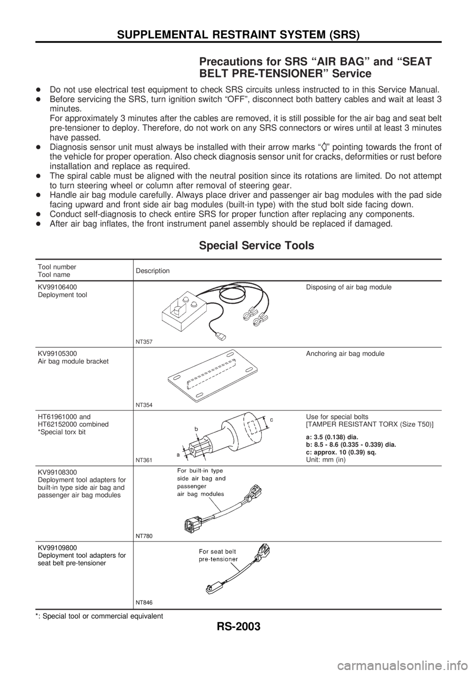
Special Service Tools
Tool number
Tool nameDescription
KV99106400
Deployment tool
NT357
Disposing of air bag module
KV99105300
Air bag module bracket
NT354
Anchoring air bag module
HT61961000 and
HT62152000 combined
*Special torx bit
NT361
Use for special bolts
[TAMPER RESISTANT TORX (Size T50)]
a: 3.5 (0.138) dia.
b: 8.5 - 8.6 (0.335 - 0.339) dia.
c: approx. 10 (0.39) sq.
Unit: mm (in)
KV99108300
Deployment tool adapters for
built-in type side air bag and
passenger air bag modules
NT780
KV99109800
Deployment tool adapters for
seat belt pre-tensioner
NT846
*: Special tool or commercial equivalent
SUPPLEMENTAL RESTRAINT SYSTEM (SRS)
RS-2003
Page 256 of 273
Removal and Installation Ð Diagnosis
Sensor Unit, Seat Belt Pre-tensioner with
Load Limiter
CAUTION:
+Before servicing SRS, turn the ignition switch off, disconnect both battery cables and wait at least
3 minutes.
+Do not use old bolts and nuts coated with bonding agent after removal; replace with new ones.
+Check diagnosis sensor unit, seat belt pre-tensioner with load limiter and satellite sensor for
proper installation.
+Check diagnosis sensor unit and satellite sensor to ensure they are free of deformities, dents,
cracks or rust. If they show any visible signs of damage, replace them with new ones.
+Check diagnosis sensor unit brackets to ensure they are free of deformities and rust.
+After replacement of diagnosis sensor unit, seat belt pre-tensioner and satellite sensor, check
SRS function and perform self-diagnosis for SRS. Refer to ªSelf-diagnosisº for details.
+Do not attempt to disassemble diagnosis sensor unit, seat belt pre-tensioner with load limiter and
satellite sensor.
+Replace diagnosis sensor unit, seat belt pre-tensioner and satellite sensor if it has been dropped
or sustained an impact.
+Do not expose seat belt pre-tensioner to temperatures exceeding 80ÉC (176ÉF).
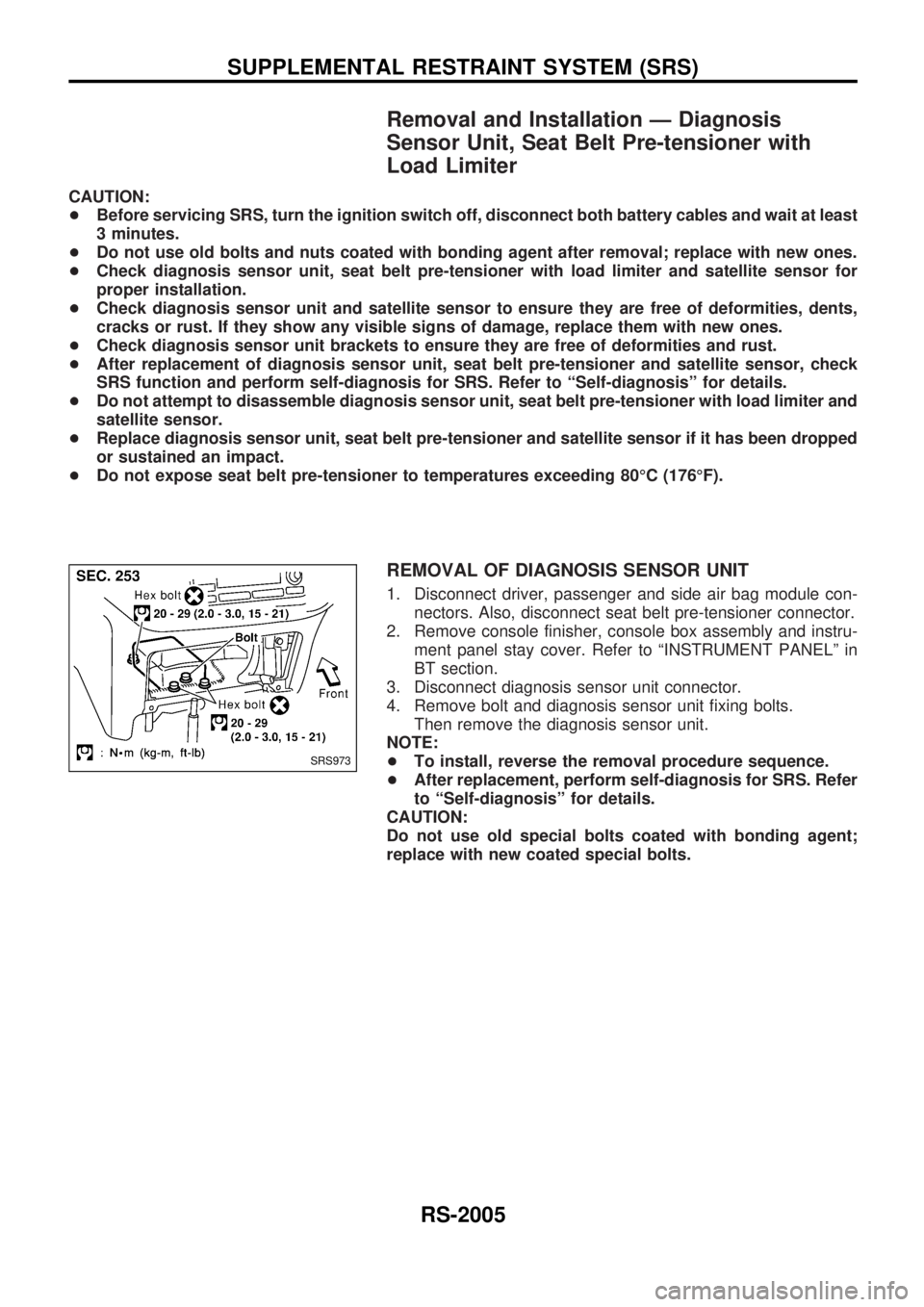
REMOVAL OF DIAGNOSIS SENSOR UNIT
1. Disconnect driver, passenger and side air bag module con-
nectors. Also, disconnect seat belt pre-tensioner connector.
2. Remove console finisher, console box assembly and instru-
ment panel stay cover. Refer to ªINSTRUMENT PANELº in
BT section.
3. Disconnect diagnosis sensor unit connector.
4. Remove bolt and diagnosis sensor unit fixing bolts.
Then remove the diagnosis sensor unit.
NOTE:
+To install, reverse the removal procedure sequence.
+After replacement, perform self-diagnosis for SRS. Refer
to ªSelf-diagnosisº for details.
CAUTION:
Do not use old special bolts coated with bonding agent;
replace with new coated special bolts.
SRS973
SUPPLEMENTAL RESTRAINT SYSTEM (SRS)
RS-2005
Page 257 of 273
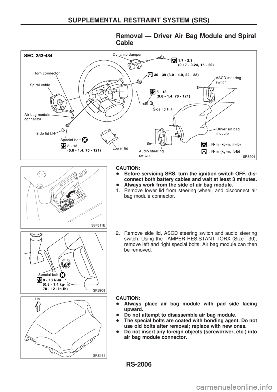
Removal Ð Driver Air Bag Module and Spiral
Cable
CAUTION:
+Before servicing SRS, turn the ignition switch OFF, dis-
connect both battery cables and wait at least 3 minutes.
+Always work from the side of air bag module.
1. Remove lower lid from steering wheel, and disconnect air
bag module connector.
2. Remove side lid, ASCD steering switch and audio steering
switch. Using the TAMPER RESISTANT TORX (Size T30),
remove left and right special bolts. Air bag module can then
be removed.
CAUTION:
+Always place air bag module with pad side facing
upward.
+Do not attempt to disassemble air bag module.
+The special bolts are coated with bonding agent. Do not
use old bolts after removal; replace with new ones.
+Do not insert any foreign objects (screwdriver, etc.) into
air bag module connector.
SRS904
SBF811E
SRS908
SRS161
SUPPLEMENTAL RESTRAINT SYSTEM (SRS)
RS-2006
Page 267 of 273
Without CONSULT-II
From User mode to Diagnosis mode
Diagnosis mode activates only when a malfunction is detected,
by turning ignition switch as follows:
1) Turn ignition switch ªONº.
2) After ªAIR BAGº warning lamp lights for 7 seconds, turn igni-
tion switch ªOFFº within 1 second.
3) Wait more than 3 seconds.
4) Repeat steps 1 to 3 three times.
5) Turn ignition switch ªONº.
SRS will not enter Diagnosis mode, if no malfunction is detected.
From Diagnosis mode to User mode
After a malfunction is repaired, switch the ignition ªOFFº for at least one second, then back ªONº. Diagno-
sis mode is returned to User mode.
If switching Diagnosis mode to User mode is required while malfunction is being detected, by turning igni-
tion switch as follows:
1) Turn ignition switch ªONº.
2) After ªAIR BAGº warning lamp lights for 7 seconds, turn ignition switch ªOFFº within 1 second.
3) Wait more than 3 seconds.
4) Repeat steps 1 to 3 three times.
5) Turn ignition switch ªONº.
SRS800
TROUBLE DIAGNOSES Ð Supplemental Restraint System (SRS)
Trouble Diagnoses Introduction (Cont'd)
RS-2016
Page 268 of 273
![NISSAN PATROL 2001 Electronic Repair Manual HOW TO ERASE SELF-DIAGNOSIS RESULTS
With CONSULT-II
+ªSELF-DIAG [CURRENT]º
A current Self-diagnosis result is displayed on the CON-
SULT-II screen in real time. After the malfunction is repaired
com NISSAN PATROL 2001 Electronic Repair Manual HOW TO ERASE SELF-DIAGNOSIS RESULTS
With CONSULT-II
+ªSELF-DIAG [CURRENT]º
A current Self-diagnosis result is displayed on the CON-
SULT-II screen in real time. After the malfunction is repaired
com](/manual-img/5/57366/w960_57366-267.png)
HOW TO ERASE SELF-DIAGNOSIS RESULTS
With CONSULT-II
+ªSELF-DIAG [CURRENT]º
A current Self-diagnosis result is displayed on the CON-
SULT-II screen in real time. After the malfunction is repaired
completely, no malfunction is detected on ªSELF-DIAG
[CURRENT]º.
+ªSELF-DIAG [PAST]º
Return to the ªSELF-DIAG [CURRENT]º CONSULT-II screen
by pushing ªBACKº key of CONSULT-II and select ªSELF-
DIAG [CURRENT]º in ªSELECT DIAG MODEº. Touch
ªERASEº in ªSELF-DIAG [CURRENT]º mode.
NOTE:
If the memory of the malfunction in ªSELF-DIAG [PAST]º is
not erased, the User mode shows the system malfunction by
the operation of the warning lamp even if the malfunction is
repaired completely.
+ªTROUBLE DIAG RECORDº
The memory of ªTROUBLE DIAG RECORDº cannot be
erased.
Without CONSULT-II
After a malfunction is repaired, return Diagnosis mode to User
mode by switching the ignition ªOFFº for at least 1 second, then
back ªONº. At that time, the self-diagnostic result is cleared.
How to Perform Trouble Diagnoses for Quick
and Accurate Repair
A good understanding of the malfunction conditions can make troubleshooting faster and more accurate.
In general, each customer feels differently about a malfunction. It is important to fully understand the symp-
toms or conditions for a customer complaint.
INFORMATION FROM CUSTOMER
WHAT ........ Vehicle model
WHEN ....... Date, Frequencies
WHERE ..... Road conditions
HOW .......... Operating conditions, Symptoms
PRELIMINARY CHECK
Check that the following parts are in good order.
+Battery [Refer to EL section (ªBATTERYº) of Service Manual.]
+Fuse [Refer to EL section (ªFuseº, ªPOWER SUPPLY ROUTINGº) of Service Manual.]
+System component-to-harness connections
SRS701
TROUBLE DIAGNOSES Ð Supplemental Restraint System (SRS)
Trouble Diagnoses Introduction (Cont'd)
RS-2017