Page 1745 of 2898
HEL667B
WARNING LAMPS
Wiring Diagram Ð WARN Ð/Sedan (Cont'd)
EL-187
Page 1746 of 2898
HEL388B
WARNING LAMPS
Wiring Diagram Ð WARN Ð/Sedan (Cont'd)
EL-188
Page 1748 of 2898
Wiring Diagram Ð WARN Ð/HatchbackNJEL0451
YEL357C
WARNING LAMPS
Wiring Diagram Ð WARN Ð/Hatchback
EL-190
Page 1749 of 2898
YEL358C
WARNING LAMPS
Wiring Diagram Ð WARN Ð/Hatchback (Cont'd)
EL-191
Page 1750 of 2898
YEL359C
WARNING LAMPS
Wiring Diagram Ð WARN Ð/Hatchback (Cont'd)
EL-192
Page 1751 of 2898
YEL360C
WARNING LAMPS
Wiring Diagram Ð WARN Ð/Hatchback (Cont'd)
EL-193
Page 1752 of 2898

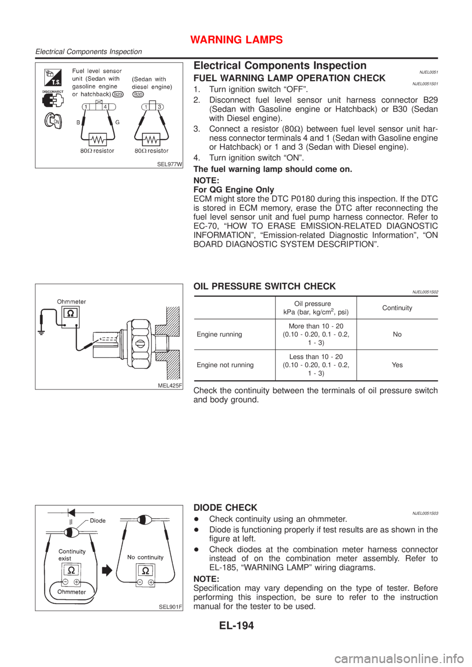
SEL977W
Electrical Components InspectionNJEL0051FUEL WARNING LAMP OPERATION CHECKNJEL0051S011. Turn ignition switch ªOFFº.
2. Disconnect fuel level sensor unit harness connector B29
(Sedan with Gasoline engine or Hatchback) or B30 (Sedan
with Diesel engine).
3. Connect a resistor (80W) between fuel level sensor unit har-
ness connector terminals 4 and 1 (Sedan with Gasoline engine
or Hatchback) or 1 and 3 (Sedan with Diesel engine).
4. Turn ignition switch ªONº.
The fuel warning lamp should come on.
NOTE:
For QG Engine Only
ECM might store the DTC P0180 during this inspection. If the DTC
is stored in ECM memory, erase the DTC after reconnecting the
fuel level sensor unit and fuel pump harness connector. Refer to
EC-70, ªHOW TO ERASE EMISSION-RELATED DIAGNOSTIC
INFORMATIONº, ªEmission-related Diagnostic Informationº, ªON
BOARD DIAGNOSTIC SYSTEM DESCRIPTIONº.
MEL425F
OIL PRESSURE SWITCH CHECKNJEL0051S02
Oil pressure
kPa (bar, kg/cm2, psi)Continuity
Engine runningMore than 10 - 20
(0.10 - 0.20, 0.1 - 0.2,
1-3)No
Engine not runningLess than 10 - 20
(0.10 - 0.20, 0.1 - 0.2,
1-3)Ye s
Check the continuity between the terminals of oil pressure switch
and body ground.
SEL901F
DIODE CHECKNJEL0051S03+Check continuity using an ohmmeter.
+Diode is functioning properly if test results are as shown in the
figure at left.
+Check diodes at the combination meter harness connector
instead of on the combination meter assembly. Refer to
EL-185, ªWARNING LAMPº wiring diagrams.
NOTE:
Specification may vary depending on the type of tester. Before
performing this inspection, be sure to refer to the instruction
manual for the tester to be used.
WARNING LAMPS
Electrical Components Inspection
EL-194
Page 1753 of 2898
Wiring Diagram Ð AT/IND Ð/With TachometerNJEL0159
HEL890A
A/T INDICATOR
Wiring Diagram Ð AT/IND Ð/With Tachometer
EL-195