2001 NISSAN ALMERA air conditioning
[x] Cancel search: air conditioningPage 1336 of 2898
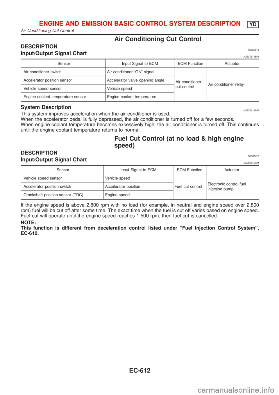
Air Conditioning Cut Control
DESCRIPTIONNJEC0614Input/Output Signal ChartNJEC0614S01
Sensor Input Signal to ECM ECM Function Actuator
Air conditioner switch Air conditioner ªONº signal
Air conditioner
cut controlAir conditioner relay Accelerator position sensor Accelerator valve opening angle
Vehicle speed sensor Vehicle speed
Engine coolant temperature sensor Engine coolant temperature
System DescriptionNJEC0614S02This system improves acceleration when the air conditioner is used.
When the accelerator pedal is fully depressed, the air conditioner is turned off for a few seconds.
When engine coolant temperature becomes excessively high, the air conditioner is turned off. This continues
until the engine coolant temperature returns to normal.
Fuel Cut Control (at no load & high engine
speed)
DESCRIPTIONNJEC0615Input/Output Signal ChartNJEC0615S01
Sensor Input Signal to ECM ECM Function Actuator
Vehicle speed sensor Vehicle speed
Fuel cut controlElectronic control fuel
injection pump Accelerator position switch Accelerator position
Crankshaft position sensor (TDC) Engine speed
If the engine speed is above 2,800 rpm with no load (for example, in neutral and engine speed over 2,800
rpm) fuel will be cut off after some time. The exact time when the fuel is cut off varies based on engine speed.
Fuel cut will operate until the engine speed reaches 1,500 rpm, then fuel cut is cancelled.
NOTE:
This function is different from deceleration control listed under ªFuel Injection Control Systemº,
EC-610.
ENGINE AND EMISSION BASIC CONTROL SYSTEM DESCRIPTIONYD
Air Conditioning Cut Control
EC-612
Page 2246 of 2898
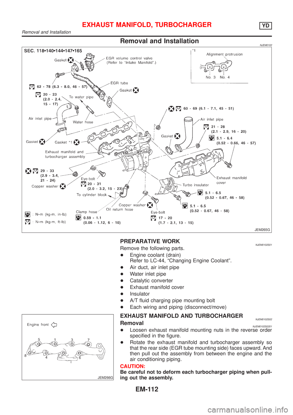
Removal and InstallationNJEM0102
JEM265G
PREPARATIVE WORKNJEM0102S01Remove the following parts.
+Engine coolant (drain)
Refer to LC-44, ªChanging Engine Coolantº.
+Air duct, air inlet pipe
+Water inlet pipe
+Catalytic converter
+Exhaust manifold cover
+Insulator
+A/T fluid charging pipe mounting bolt
+Each wiring and piping (disconnect/move)
JEM266G
EXHAUST MANIFOLD AND TURBOCHARGERNJEM0102S02RemovalNJEM0102S0201+Loosen exhaust manifold mounting nuts in the reverse order
specified in the figure.
+Rotate the exhaust manifold and turbocharger assembly so
that the rear side (EGR tube mounting side) faces upward. And
then pull out the assembly from between the engine and the
air conditioning piping.
CAUTION:
Be careful not to deform each turbocharger piping when pull-
ing out the assembly.
EXHAUST MANIFOLD, TURBOCHARGERYD
Removal and Installation
EM-112
Page 2347 of 2898
GENERAL INFORMATION
SECTION
GI
CONTENTS
PRECAUTIONS...............................................................3
Precautions ..................................................................3
PRECAUTIONS FOR SUPPLEMENTAL
RESTRAINT SYSTEM (SRS)²AIR BAG²AND
²SEAT BELT PRE-TENSIONER²
.................................3
PRECAUTIONS FOR NATS (NISSAN ANTI-THEFT
SYSTEM)
..................................................................3
GENERAL PRECAUTIONS.........................................4
PRECAUTIONS FOR MULTIPORT FUEL
INJECTION SYSTEM OR ENGINE CONTROL
SYSTEM
...................................................................6
PRECAUTIONS FOR THREE WAY CATALYST...........6
PRECAUTIONS FOR HOSES.....................................6
PRECAUTIONS FOR ENGINE OILS...........................7
PRECAUTIONS FOR FUEL........................................8
PRECAUTIONS FOR AIR CONDITIONING..................8
HOW TO USE THIS MANUAL........................................9
HOW TO READ WIRING DIAGRAMS.......................... 11
Sample/Wiring Diagram - EXAMPL - ........................ 11
OPTIONAL SPLICE..................................................12
Description .................................................................13
CONNECTOR SYMBOLS.........................................15
HARNESS INDICATION...........................................16
COMPONENT INDICATION......................................16
SWITCH POSITIONS...............................................16
DETECTABLE LINES AND NON-DETECTABLE
LINES
.....................................................................17
MULTIPLE SWITCH.................................................18
REFERENCE AREA.................................................19
HOW TO PERFORM EFFICIENT DIAGNOSES
FOR AN ELECTRICAL INCIDENT...............................21
Work Flow ..................................................................21
Incident Simulation Tests ...........................................22
INTRODUCTION......................................................22
VEHICLE VIBRATION..............................................22
HEAT SENSITIVE....................................................23
FREEZING..............................................................23
WATER INTRUSION................................................24
ELECTRICAL LOAD.................................................24
COLD OR HOT START UP.......................................24
Circuit Inspection .......................................................24
INTRODUCTION......................................................24
TESTING FOR²OPENS²IN THE CIRCUIT................25
TESTING FOR²SHORTS²IN THE CIRCUIT..............26
GROUND INSPECTION...........................................27
VOLTAGE DROP TESTS..........................................27
CONTROL UNIT CIRCUIT TEST...............................29
HOW TO FOLLOW TROUBLE DIAGNOSES...............31
How to Follow Test Groups in Trouble Diagnoses ....32
Key to Symbols Signifying Measurements or
Procedures.................................................................33
CONSULT-II CHECKING SYSTEM...............................35
Function and System Application ..............................35
Nickel Metal Hydride Battery Replacement...............36
Checking Equipment..................................................36
CONSULT-II Data Link Connector (DLC) Circuit ......37
INSPECTION PROCEDURE.....................................37
IDENTIFICATION INFORMATION................................38
Model Variation ..........................................................38
PREFIX AND SUFFIX DESIGNATIONS.....................39
Identification Number .................................................39
VEHICLE IDENTIFICATION NUMBER
ARRANGEMENT
.....................................................40
IDENTIFICATION PLATE..........................................40
ENGINE SERIAL NUMBER.......................................41
AUTOMATIC TRANSAXLE NUMBER........................41
MANUAL TRANSAXLE NUMBER..............................42
Dimensions ................................................................43
Wheels and Tires .......................................................43
LIFTING POINTS AND TOW TRUCK TOWING...........44
Preparation ................................................................44
SPECIAL SERVICE TOOLS......................................44
Board-on Lift ..............................................................44
Garage Jack and Safety Stand .................................45
2-pole Lift ...................................................................46
Tow Truck Towing ......................................................47
TOWING AN AUTOMATIC TRANSAXLE MODEL
WITH FOUR WHEELS ON GROUND
........................47
TOWING AN AUTOMATIC TRANSAXLE MODEL
WITH REAR WHEELS RAISED (WITH FRONT
WHEELS ON GROUND)
..........................................47
Page 2354 of 2898
+Do not use gasoline, kerosine, diesel fuel, gas oil, thinners or
solvents for cleaning skin.
+If skin disorders develop, obtain medical advice without delay.
+Where practicable, degrease components prior to handling.
+Where there is a risk of eye contact, eye protection should be
worn, for example, chemical goggles or face shields; in addi-
tion an eye wash facility should be provided.
Environmental Protection PrecautionsNJGI0001S0702Burning used engine oil in small space heaters or boilers can be
recommended only for units of approved design. The heating sys-
tem must meet the requirements of HM Inspectorate of Pollution for
small burners of less than 0.4 MW. If in doubt, check with the
appropriate local authority and/or manufacturer of the approved
appliance.
Dispose of used oil and used oil filters through authorized waste
disposal contractors to licensed waste disposal sites, or to the
waste oil reclamation trade. If in doubt, contact the local authority
for advice on disposal facilities.
It is illegal to pour used oil on to the ground, down sewers or drains,
or into water courses.
The regulations concerning the pollution vary between
regions.
PRECAUTIONS FOR FUELNJGI0001S08Gasoline EngineNJGI0001S0803Models with three way catalyst
Unleaded premium gasoline of at least 95 octane (RON)
If premium gasoline is not available, unleaded regular gaso-
line with an octane rating of 91 (RON) may be temporarily
used, but only under the following precautions:
+Have the fuel tank filled only partially with unleaded regu-
lar gasoline, and fill up with premium unleaded gasoline
as soon as possible.
+Avoid full throttle driving and abrupt acceleration.
CAUTION:
Do not use leaded gasoline. Using leaded gasoline will dam-
age the three way catalyst.
Diesel Engine*:NJGI0001S0804Diesel fuel of at least 50 cetane
* If two types of diesel fuel are available, use summer or winter
fuel properly according to the following temperature conditions.
+Above þ7ÉC (20ÉF) ... Summer type diesel fuel.
+Below þ7ÉC (20ÉF) ... Winter type diesel fuel.
CAUTION:
+Do not use home heating oil, gasoline, or other alternate
fuels in your diesel engine. The use of those can cause
engine damage.
+Do not use summer fuel at temperatures below þ7ÉC
(20ÉF). The cold temperatures will cause wax to form in the
fuel. As a result, it may prevent the engine from running
smoothly.
+Do not add gasoline or other alternate fuels to diesel fuel.
PRECAUTIONS FOR AIR CONDITIONINGNJGI0001S09Use an approved refrigerant recovery unit any time the air condi-
tioning system must be discharged. Refer to HA-78, ªHFC-134a
(R-134a) Service Procedureº for specific instructions.
PRECAUTIONS
Precautions (Cont'd)
GI-8
Page 2402 of 2898
Supplemental Restraint System (SRS) ªAIR
BAGº and ªSEAT BELT PRE-TENSIONERº
NJHA0190The Supplemental Restraint System such as ªAIR BAGº and ªSEAT BELT PRE-TENSIONERº used along with
a seat belt, helps to reduce the risk or severity of injury to the driver and front passenger for certain types of
collision. The SRS system composition which is available to NISSAN MODEL N16 is as follows (The compo-
sition varies according to the destination and optional equipment.):
+For a frontal collision
The Supplemental Restraint System consists of driver air bag module (located in the center of the steer-
ing wheel), front passenger air bag module (located on the instrument panel on passenger side), front seat
belt pre-tensioners, a diagnosis sensor unit, warning lamp, wiring harness and spiral cable.
+For a side collision
The Supplemental Restraint System consists of front side air bag module (located in the outer side of front
seat), side air bag (satellite) sensor, diagnosis sensor unit (one of components of air bags for a frontal
collision), wiring harness, warning lamp (one of components of air bags for a frontal collision).
Information necessary to service the system safely is included in theRS sectionof this Service Manual.
WARNING:
+To avoid rendering the SRS inoperative, which could increase the risk of personal injury or death
in the event of a collision which would result in air bag inflation, all maintenance should be per-
formed by an authorized NISSAN dealer.
+Improper maintenance, including incorrect removal and installation of the SRS, can lead to per-
sonal injury caused by unintentional activation of the system. For removal of Spiral Cable and Air
Bag Module, see the RS section.
+Do not use electrical test equipment on any circuit related to the SRS unless instructed to in this
Service Manual. Spiral cable and wiring harnesses covered with yellow insulation tape either just
before the harness connectors or for the complete harness are related to the SRS.
Precautions for Working with HFC-134a
(R-134a)
NJHA0113WARNING:
+CFC-12 (R-12) refrigerant and HFC-134a (R-134a) refrigerant are not compatible. These refrigerants
must never be mixed, even in the smallest amounts. If the refrigerants are mixed, compressor fail-
ure is likely to occur.
+Use only specified lubricant for the HFC-134a (R-134a) A/C system and HFC-134a (R-134a) compo-
nents. If lubricant other than that specified is used, compressor failure is likely to occur.
+The specified HFC-134a (R-134a) lubricant rapidly absorbs moisture from the atmosphere. The fol-
lowing handling precautions must be observed:
a) When removing refrigerant components from a vehicle, immediately cap (seal) the component to
minimize the entry of moisture from the atmosphere.
b) When installing refrigerant components to a vehicle, do not remove the caps (unseal) until just
before connecting the components. Connect all refrigerant loop components as quickly as pos-
sible to minimize the entry of moisture into system.
c) Only use the specified lubricant from a sealed container. Immediately reseal containers of lubri-
cant. Without proper sealing, lubricant will become moisture saturated and should not be used.
d) Avoid breathing A/C refrigerant and lubricant vapor or mist. Exposure may irritate eyes, nose
and throat. Remove R-134a from the A/C system, using certified service equipment meeting
requirements of R-134a recycling equipment, or R-134a recovery equipment. If accidental system
discharge occurs, ventilate work area before resuming service. Additional health and safety
information may be obtained from refrigerant and lubricant manufacturers.
e) Do not allow lubricant (Nissan A/C System Oil Type S) to come in contact with styrofoam parts.
Damage may result.
General Refrigerant PrecautionsNJHA0114WARNING:
+Do not release refrigerant into the air. Use approved recovery/recycling equipment to capture the
refrigerant every time an air conditioning system is discharged.
+Always wear eye and hand protection (goggles and gloves) when working with any refrigerant or
air conditioning system.
PRECAUTIONS
Supplemental Restraint System (SRS) ªAIR BAGº and ªSEAT BELT PRE-TENSIONERº
HA-2
Page 2414 of 2898
CSV613 Variable Displacement Compressor
GENERAL INFORMATIONNJHA02061. The CSV613 compressor differs from previous units. The vent temperatures of the CSV613 compressor
do not drop too far below 5ÉC (41ÉF) when:
+evaporator intake air temperature is less than 20ÉC (68ÉF)
+engine is running at speeds less than 1,500 rpm.
This is because the CSV613 compressor provides a means of ªcapacityº control.
2. The CSV613 compressor provides refrigerant control under varying conditions. During cold winters, it may
not produce high refrigerant pressure discharge (compared to previous units) when used with air condi-
tioning systems.
3. A ªclankingº sound may occasionally be heard during refrigerant charge. The sound indicates that the tilt
angle of the swash plate has changed and is not a problem.
4. For air conditioning systems with the CSV613 compressor, the clutch remains engaged unless: the sys-
tem main switch, fan switch or ignition switch is turned OFF. When ambient (outside) temperatures are
low or when the amount of refrigerant is insufficient, the clutch is disengaged to protect the compressor.
5. A constant range of suction pressure is maintained when engine speed is greater than a certain value. It
normally ranges from 147 to 177 kPa (1.47 to 1.77 bar, 1.5 to 1.8 kg/cm
2, 21 to 26 psi) under varying con-
ditions.
In previous compressors, however, suction pressure was reduced with increases in engine speed.
DESCRIPTION
CSV613 Variable Displacement Compressor
HA-14
Page 2471 of 2898
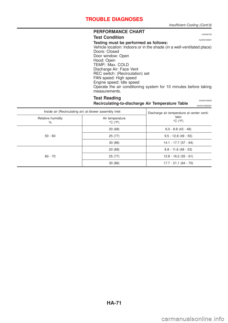
PERFORMANCE CHART=NJHA0150Test ConditionNJHA0150S01Testing must be performed as follows:
Vehicle location: Indoors or in the shade (in a well-ventilated place)
Doors: Closed
Door window: Open
Hood: Open
TEMP.: Max. COLD
Discharge Air: Face Vent
REC switch: (Recirculation) set
FAN speed: High speed
Engine speed: Idle speed
Operate the air conditioning system for 10 minutes before taking
measurements.
Test ReadingNJHA0150S02Recirculating-to-discharge Air Temperature TableNJHA0150S0201
Inside air (Recirculating air) at blower assembly inlet
Discharge air temperature at center venti-
lator
ÉC (ÉF) Relative humidity
%Air temperature
ÉC (ÉF)
50-6020 (68) 6.0 - 8.8 (43 - 48)
25 (77) 9.5 - 12.8 (49 - 55)
30 (86) 14.1 - 17.7 (57 - 64)
60-7020 (68) 8.8 - 11.6 (48 - 53)
25 (77) 12.8 - 16.2 (55 - 61)
30 (86) 17.7 - 21.1 (64 - 70)
TROUBLE DIAGNOSES
Insufficient Cooling (Cont'd)
HA-71
Page 2475 of 2898
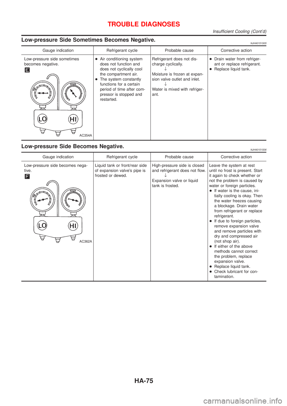
Low-pressure Side Sometimes Becomes Negative.NJHA0151S05
Gauge indication Refrigerant cycle Probable cause Corrective action
Low-pressure side sometimes
becomes negative.
AC354A
+Air conditioning system
does not function and
does not cyclically cool
the compartment air.
+The system constantly
functions for a certain
period of time after com-
pressor is stopped and
restarted.Refrigerant does not dis-
charge cyclically.
¯
Moisture is frozen at expan-
sion valve outlet and inlet.
¯
Water is mixed with refriger-
ant.+Drain water from refriger-
ant or replace refrigerant.
+Replace liquid tank.
Low-pressure Side Becomes Negative.NJHA0151S06
Gauge indication Refrigerant cycle Probable cause Corrective action
Low-pressure side becomes nega-
tive.
AC362A
Liquid tank or front/rear side
of expansion valve's pipe is
frosted or dewed.High-pressure side is closed
and refrigerant does not flow.
¯
Expansion valve or liquid
tank is frosted.Leave the system at rest
until no frost is present. Start
it again to check whether or
not the problem is caused by
water or foreign particles.
+If water is the cause, ini-
tially cooling is okay. Then
the water freezes causing
a blockage. Drain water
from refrigerant or replace
refrigerant.
+If due to foreign particles,
remove expansion valve
and remove particles with
dry and compressed air
(not shop air).
+If either of the above
methods cannot correct
the problem, replace
expansion valve.
+Replace liquid tank.
+Check lubricant for con-
tamination.
TROUBLE DIAGNOSES
Insufficient Cooling (Cont'd)
HA-75