Page 286 of 2493
+Replace the radiator cap if abnormalities are found with the
negative pressure valve, or if the valve opening pressure is out
of the standard range.
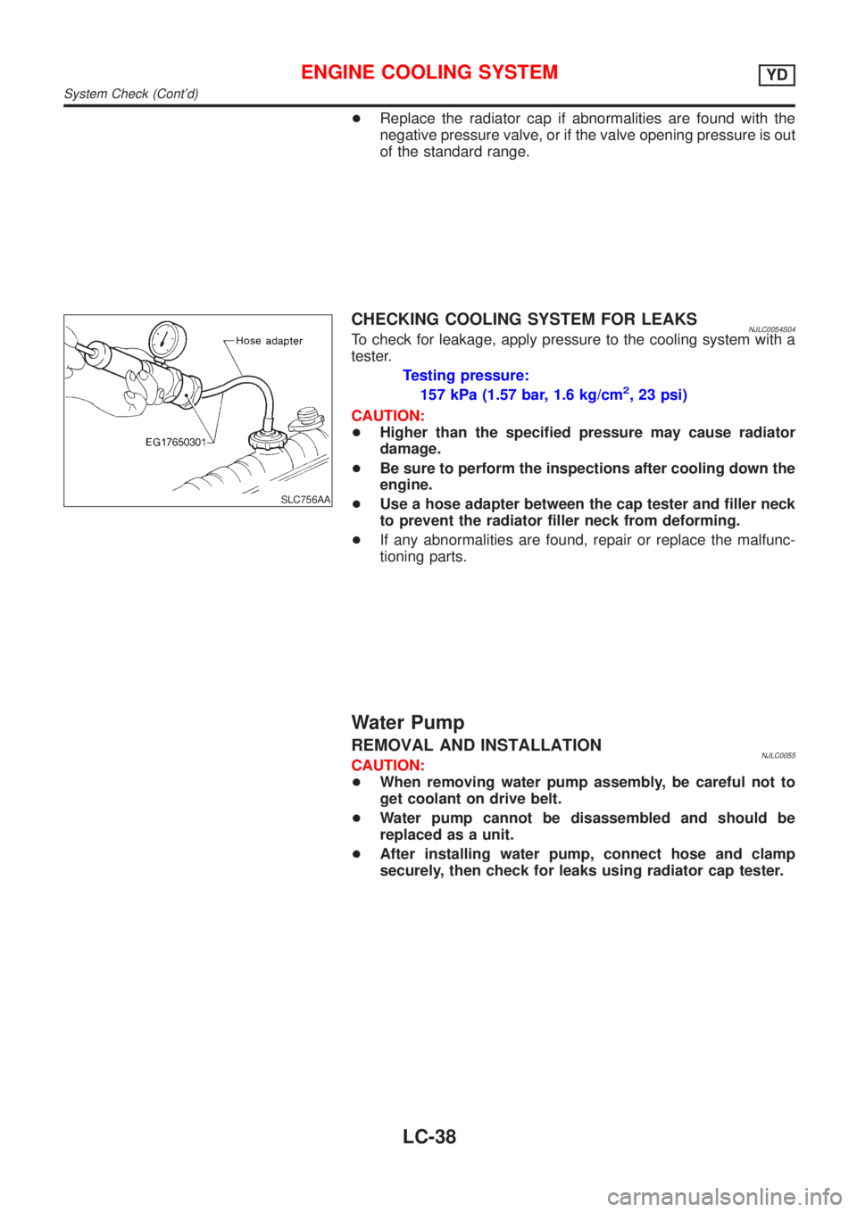
SLC756AA
CHECKING COOLING SYSTEM FOR LEAKSNJLC0054S04To check for leakage, apply pressure to the cooling system with a
tester.
Testing pressure:
157 kPa (1.57 bar, 1.6 kg/cm
2, 23 psi)
CAUTION:
+Higher than the specified pressure may cause radiator
damage.
+Be sure to perform the inspections after cooling down the
engine.
+Use a hose adapter between the cap tester and filler neck
to prevent the radiator filler neck from deforming.
+If any abnormalities are found, repair or replace the malfunc-
tioning parts.
Water Pump
REMOVAL AND INSTALLATIONNJLC0055CAUTION:
+When removing water pump assembly, be careful not to
get coolant on drive belt.
+Water pump cannot be disassembled and should be
replaced as a unit.
+After installing water pump, connect hose and clamp
securely, then check for leaks using radiator cap tester.
ENGINE COOLING SYSTEMYD
System Check (Cont'd)
LC-38
Page 287 of 2493
JLC294B
REMOVALNJLC00561. Remove the undercover, splash cover (right), and accessory
belt.
2. Drain engine coolant. Refer to LC-43, ªChanging Engine Cool-
antº.
3. Support the bottom of the oil pan with a floor jack etc., and
remove the right engine mount bracket (front side of the
engine).
4. Remove the water pump pulley.
+Loosen the pulley bolts after fixing the pulley using a screw-
driver etc.
5. Remove engine mount brackets.
6. Remove the water pump.
INSPECTIONNJLC0057+Check for rust and contamination adhering to the water pump
and vane.
+Turn the pump shaft by hand, and check that the pump turns
smoothly without looseness.
INSTALLATIONNJLC0058+Install the parts in the reverse order of removal.
+Install the water pump pulley with the front mark (painted white,
used to prevent errors during assembly) facing the front of the
engine. Refer to the figure above.
ENGINE COOLING SYSTEMYD
Water Pump (Cont'd)
LC-39
Page 294 of 2493
Radiator (Aluminum type)=NJLC0082Refer to LC-20, ªRadiator (Aluminum type)º.
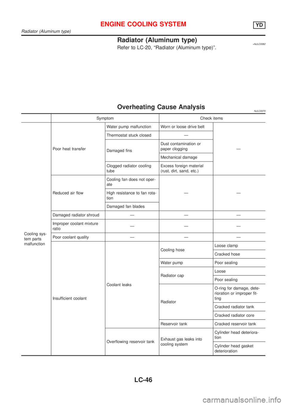
Overheating Cause AnalysisNJLC0070
Symptom Check items
Cooling sys-
tem parts
malfunctionPoor heat transferWater pump malfunction Worn or loose drive belt
Ð Thermostat stuck closed Ð
Damaged finsDust contamination or
paper clogging
Mechanical damage
Clogged radiator cooling
tubeExcess foreign material
(rust, dirt, sand, etc.)
Reduced air flowCooling fan does not oper-
ate
ÐÐ High resistance to fan rota-
tion
Damaged fan blades
Damaged radiator shroud Ð Ð Ð
Improper coolant mixture
ratioÐÐÐ
Poor coolant quality Ð Ð Ð
Insufficient coolantCoolant leaksCooling hoseLoose clamp
Cracked hose
Water pump Poor sealing
Radiator capLoose
Poor sealing
RadiatorO-ring for damage, dete-
rioration or improper fit-
ting
Cracked radiator tank
Cracked radiator core
Reservoir tank Cracked reservoir tank
Overflowing reservoir tankExhaust gas leaks into
cooling systemCylinder head deteriora-
tion
Cylinder head gasket
deterioration
ENGINE COOLING SYSTEMYD
Radiator (Aluminum type)
LC-46
Page 420 of 2493

Symptom Matrix ChartNJEC0041SYSTEM Ð ENGINE CONTROL SYSTEMNJEC0041S01
SYMPTOM
Reference
page
HARD/NO START/RESTART (EXCP. HA)
ENGINE STALL
HESITATION/SURGING/FLAT SPOT
SPARK KNOCK/DETONATION
LACK OF POWER/POOR ACCELERATION
HIGH IDLE/LOW IDLE
ROUGH IDLE/HUNTING
IDLING VIBRATION
SLOW/NO RETURN TO IDLE
OVERHEATS/WATER TEMPERATURE HIGH
EXCESSIVE FUEL CONSUMPTION
EXCESSIVE OIL CONSUMPTION
BATTERY DEAD (UNDER CHARGE)
Warranty symptom code AA AB AC AD AE AF AG AH AJ AK AL AM HA
Fuel Fuel pump circuit11232 22 3 2EC-464
Fuel pressure regulator sys-
tem334444444 4EC-39
Injector circuit11232 22 2EC-447
Evaporative emission sys-
tem334444444 4EC-33
Air Positive crankcase ventila-
tion system334444444 41EC-37
Incorrect idle speed adjust-
ment3 3 1 1 1 1 1 EC-41
IACV-AAC valve circuit112332222 2 2EC-313
Ignition Incorrect ignition timing
adjustment33111 11 1EC-41
Ignition circuit11222 22 2EC-451
EGR EGR volume control valve
circuit2233 3EC-293
EGR system212333223 3EC-285,
293, 353
Main power supply and ground circuit22333 33 23 2EC-145
Air conditioner circuit223333333 3 2HAsection
1 - 6: The numbers refer to the order of inspection.
(continued on next page)
TROUBLE DIAGNOSIS Ð GENERAL DESCRIPTIONQG
Symptom Matrix Chart
EC-124
Page 423 of 2493
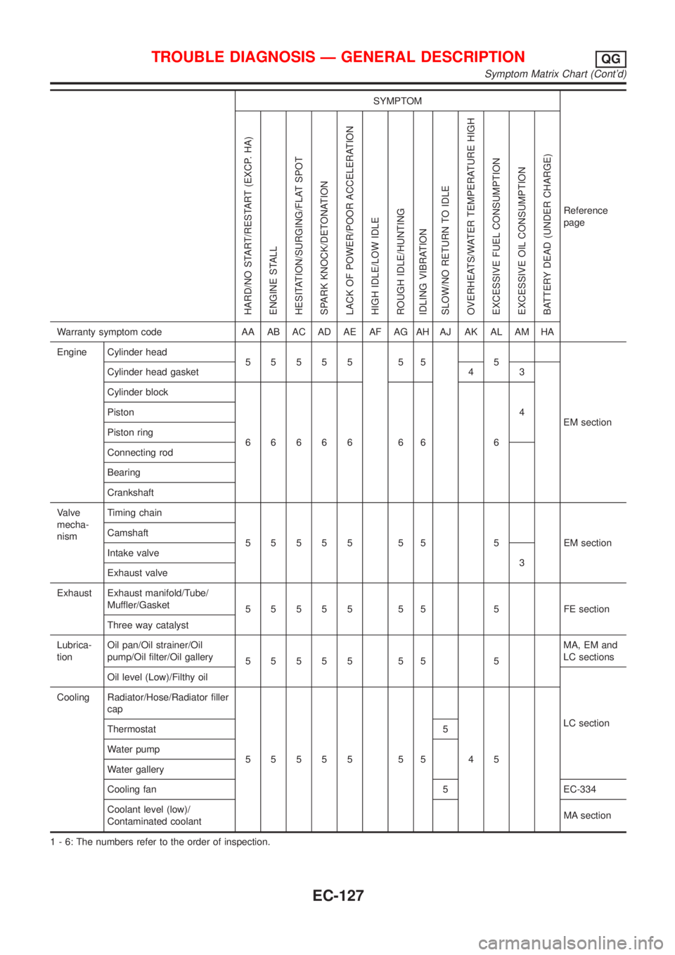
SYMPTOM
Reference
page
HARD/NO START/RESTART (EXCP. HA)
ENGINE STALL
HESITATION/SURGING/FLAT SPOT
SPARK KNOCK/DETONATION
LACK OF POWER/POOR ACCELERATION
HIGH IDLE/LOW IDLE
ROUGH IDLE/HUNTING
IDLING VIBRATION
SLOW/NO RETURN TO IDLE
OVERHEATS/WATER TEMPERATURE HIGH
EXCESSIVE FUEL CONSUMPTION
EXCESSIVE OIL CONSUMPTION
BATTERY DEAD (UNDER CHARGE)
Warranty symptom code AA AB AC AD AE AF AG AH AJ AK AL AM HA
Engine Cylinder head
55555 55 5
EM section Cylinder head gasket 4 3
Cylinder block
66666 66 64 Piston
Piston ring
Connecting rod
Bearing
Crankshaft
Valve
mecha-
nismTiming chain
55555 55 5 EMsection Camshaft
Intake valve
3
Exhaust valve
Exhaust Exhaust manifold/Tube/
Muffler/Gasket
55555 55 5 FEsection
Three way catalyst
Lubrica-
tionOil pan/Oil strainer/Oil
pump/Oil filter/Oil gallery
55555 55 5MA, EM and
LC sections
Oil level (Low)/Filthy oil
LC section Cooling Radiator/Hose/Radiator filler
cap
55555 55 45 Thermostat 5
Water pump
Water gallery
Cooling fan 5 EC-334
Coolant level (low)/
Contaminated coolantMA section
1 - 6: The numbers refer to the order of inspection.
TROUBLE DIAGNOSIS Ð GENERAL DESCRIPTIONQG
Symptom Matrix Chart (Cont'd)
EC-127
Page 638 of 2493
9 CHECK COOLING FAN MOTORS-1 AND -2
Refer to ªComponent Inspectionº, EC-345.
OK or NG
OK©GO TO 10.
NG©Replace cooling fan motors.
10 CHECK INTERMITTENT INCIDENT
Perform ªTROUBLE DIAGNOSIS FOR INTERMITTENT INCIDENTº, EC-144.
©INSPECTION END
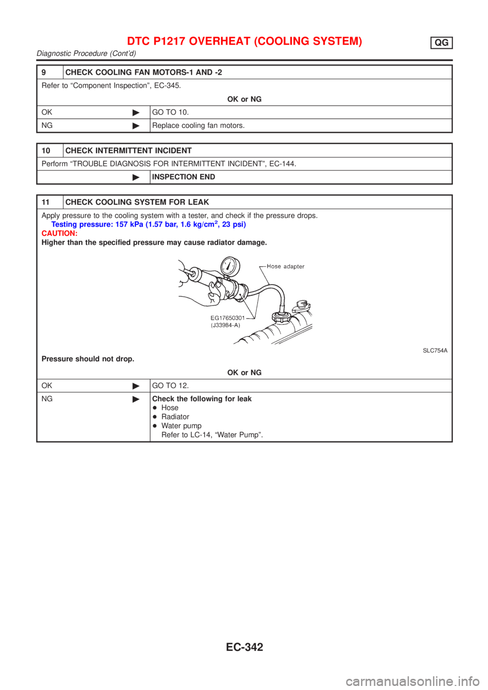
11 CHECK COOLING SYSTEM FOR LEAK
Apply pressure to the cooling system with a tester, and check if the pressure drops.
Testing pressure: 157 kPa (1.57 bar, 1.6 kg/cm2, 23 psi)
CAUTION:
Higher than the specified pressure may cause radiator damage.
SLC754A
Pressure should not drop.
OK or NG
OK©GO TO 12.
NG©Check the following for leak
+Hose
+Radiator
+Water pump
Refer to LC-14, ªWater Pumpº.
DTC P1217 OVERHEAT (COOLING SYSTEM)QG
Diagnostic Procedure (Cont'd)
EC-342
Page 816 of 2493
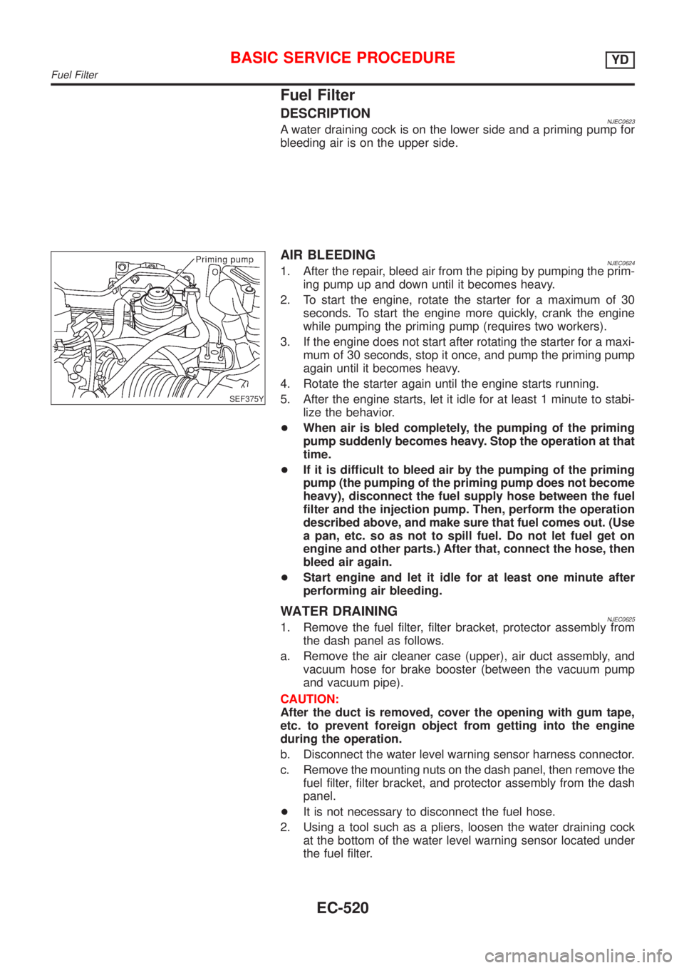
Fuel Filter
DESCRIPTIONNJEC0623A water draining cock is on the lower side and a priming pump for
bleeding air is on the upper side.
SEF375Y
AIR BLEEDINGNJEC06241. After the repair, bleed air from the piping by pumping the prim-
ing pump up and down until it becomes heavy.
2. To start the engine, rotate the starter for a maximum of 30
seconds. To start the engine more quickly, crank the engine
while pumping the priming pump (requires two workers).
3. If the engine does not start after rotating the starter for a maxi-
mum of 30 seconds, stop it once, and pump the priming pump
again until it becomes heavy.
4. Rotate the starter again until the engine starts running.
5. After the engine starts, let it idle for at least 1 minute to stabi-
lize the behavior.
+When air is bled completely, the pumping of the priming
pump suddenly becomes heavy. Stop the operation at that
time.
+If it is difficult to bleed air by the pumping of the priming
pump (the pumping of the priming pump does not become
heavy), disconnect the fuel supply hose between the fuel
filter and the injection pump. Then, perform the operation
described above, and make sure that fuel comes out. (Use
a pan, etc. so as not to spill fuel. Do not let fuel get on
engine and other parts.) After that, connect the hose, then
bleed air again.
+Start engine and let it idle for at least one minute after
performing air bleeding.
WATER DRAININGNJEC06251. Remove the fuel filter, filter bracket, protector assembly from
the dash panel as follows.
a. Remove the air cleaner case (upper), air duct assembly, and
vacuum hose for brake booster (between the vacuum pump
and vacuum pipe).
CAUTION:
After the duct is removed, cover the opening with gum tape,
etc. to prevent foreign object from getting into the engine
during the operation.
b. Disconnect the water level warning sensor harness connector.
c. Remove the mounting nuts on the dash panel, then remove the
fuel filter, filter bracket, and protector assembly from the dash
panel.
+It is not necessary to disconnect the fuel hose.
2. Using a tool such as a pliers, loosen the water draining cock
at the bottom of the water level warning sensor located under
the fuel filter.
BASIC SERVICE PROCEDUREYD
Fuel Filter
EC-520
Page 817 of 2493
3. Install the fuel filter, filter bracket, and protector assembly tem-
porarily. Then, drain the water by pumping the priming pump
with the filter standing straight.
+Extend the drain hose if necessary.
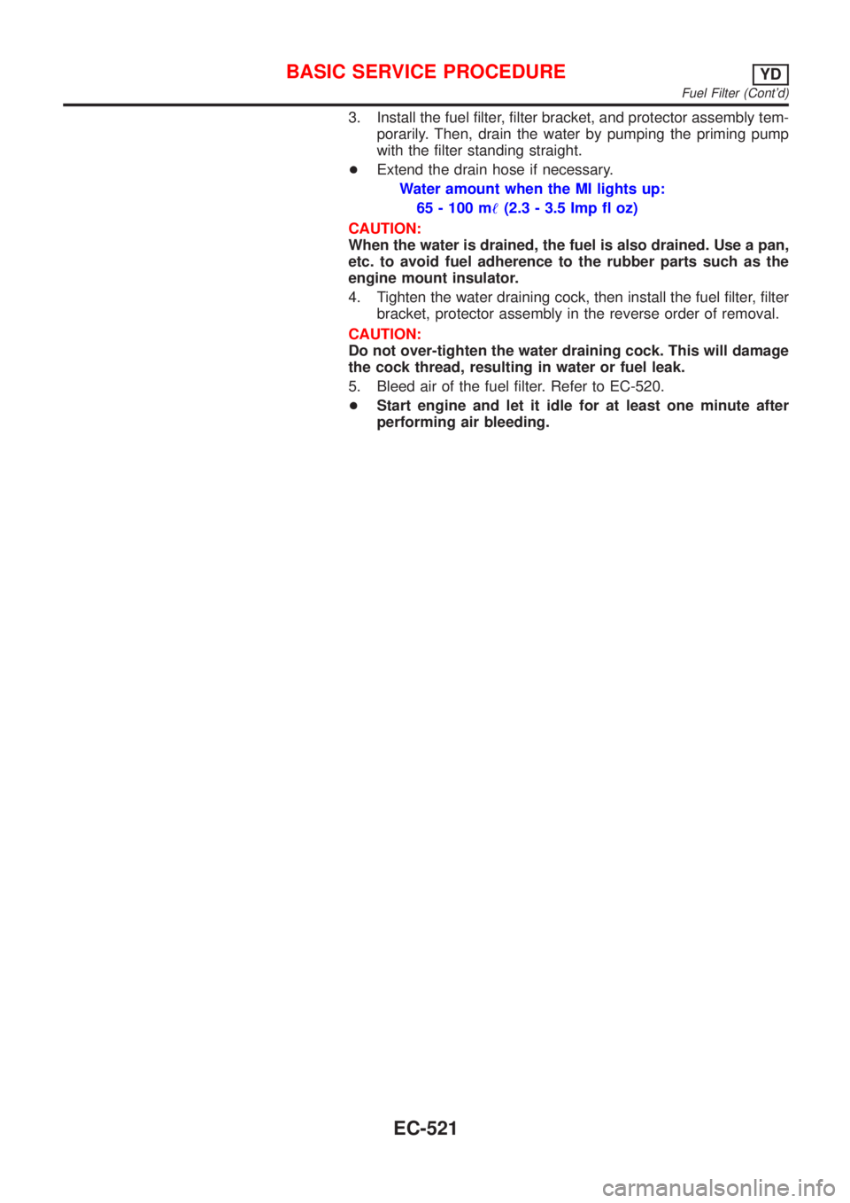
Water amount when the MI lights up:
65 - 100 m!(2.3 - 3.5 Imp fl oz)
CAUTION:
When the water is drained, the fuel is also drained. Use a pan,
etc. to avoid fuel adherence to the rubber parts such as the
engine mount insulator.
4. Tighten the water draining cock, then install the fuel filter, filter
bracket, protector assembly in the reverse order of removal.
CAUTION:
Do not over-tighten the water draining cock. This will damage
the cock thread, resulting in water or fuel leak.
5. Bleed air of the fuel filter. Refer to EC-520.
+Start engine and let it idle for at least one minute after
performing air bleeding.
BASIC SERVICE PROCEDUREYD
Fuel Filter (Cont'd)
EC-521