Page 231 of 317
228 First aid kit
Te ch n ica l
data Instruments
and controlsOperation DrivingInstrument
cluster displayPractical hintsCar care Index
First aid kit
All except model ML 55 AMG:
The first aid kit is located behind the cover in the left
rear cargo compartment trim panel.
Turn both handles (1) left and open cover.
Model ML 55 AMG:
The first aid kit is stored inside the spare wheel cover
located in the cargo compartment.
Open buckles and remove spare wheel cover,
see page 242.Fuses
Before replacing a blown fuse, determine the cause of
the short circuit.
Spare fuses and a special fuse puller are supplied inside
the fuse box cover. Observe amperage and color of fuse.
Always use a new fuse for replacement. Never attempt to
repair or bridge a blown fuse.
A fuse chart can be found inside the corresponding fuse
box cover.
Page 240 of 317
237 Windshield wiper
Te ch n ica l
data Instruments
and controlsOperation DrivingInstrument
cluster displayPractical hintsCar care Index Windshield and headlamp washer
fluid mixing ratio
For temperatures above freezing:
MB Windshield Washer Concentrate “S” and water
1 part “S” to 100 parts water
(40 ml “S” to 1 gallon water).
For temperature below freezing:
MB Windshield Washer Concentrate “S” and
commercially available premixed windshield washer
solvent / antifreeze
1 part “S” to 100 parts solvent
(40 ml “S” to 1 gallon solvent).Vehicle jack, wheel bolt wrench and screwdriver
Wa r n i n g !
The jack is designed exclusively for jacking up the
vehicle at the jack take-up brackets built into either
side of the vehicle. To help avoid personal injury,
use the jack only to lift the vehicle during a wheel
change. Never get beneath the vehicle while it is
supported by the jack. Keep hands and feet away
from the area under the lifted vehicle. Always
firmly set parking brake and block wheels before
raising vehicle with jack.Do not disengage parking brake while the vehicle is
raised. Be certain that the jack is always vertical
when in use, especially on hills. Always try to use
the jack on level surface. Be sure that the jack arm
end is fully seated in the jack take-up bracket.
Always lower the vehicle onto sufficient capacity
jackstands before working under the vehicle.
Page 248 of 317
245 Tires, Wheels
Te ch n ica l
data Instruments
and controlsOperation DrivingInstrument
cluster displayPractical hintsCar care Index Changing wheels
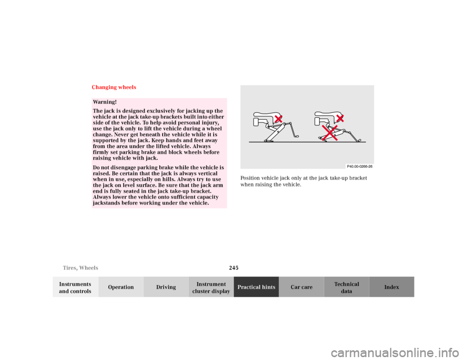
Position vehicle jack only at the jack take-up bracket
when raising the vehicle.
Wa r n i n g !
The jack is designed exclusively for jacking up the
veh icle at the jack take-u p brackets bu ilt i nto eit her
side of the vehicle. To help avoid personal injury,
use the jack only to lift the vehicle during a wheel
change. Never get beneath the vehicle while it is
supported by the jack. Keep hands and feet away
from the area under the lifted vehicle. Always
firmly set parking brake and block wheels before
raising vehicle with jack.Do not disengage parking brake while the vehicle is
raised. Be certain that the jack is always vertical
when in use, especially on hills. Always try to use
the jack on level surface. Be sure that the jack arm
end is fully seated in the jack take-up bracket.
Always lower the vehicle onto sufficient capacity
jackstands before working under the vehicle.
Page 253 of 317
250 Tires, Wheels
Te ch n ica l
data Instruments
and controlsOperation DrivingInstrument
cluster displayPractical hintsCar care Index
Tire inflation pressure
A table (see fuel filler flap) lists the tire inflation
pressures specified for Mercedes-Benz recommended
tires as well as for the varying operating conditions.
Important!
Tire pressure changes by approximately 1.5 psi (0.1 bar)
per 18°F (10°C) of air temperature change. Keep this in
mind when checking tire pressure inside a garage –
especially in the winter.
Example:
If garage temperature = approximately +68°F (+20°C)
and ambient temperature = approximately +32°F (0°C)
then the adjusted air pressure = specified air pressure
+3 psi (+0.2 bar).Tire pressures listed for light loads are minimum values
offering high driving comfort. Increased inflation
pressures for heavy loads produce favorable handling
characteristics with lighter loads and are perfectly
permissible. The ride of the vehicle, however, will
become somewhat harder.
Tire temperature and pressure increase with the vehicle
speed. Tire pressure should therefore only be checked
and corrected on cold tires. Correct tire pressure in
warm tires only if pressure has dropped below the
pressure listed in the table and the respective operating
conditions are taken into consideration.
An underinf lated tire due to a slow leak (e.g. due to a
nail in the tire) may cause damage such as tread
separation, bulging etc.. Regular tire pressure checks
(including the spare tire) at intervals of no more than
14 days are therefore essential.
Page 255 of 317
252 Battery
Te ch n ica l
data Instruments
and controlsOperation DrivingInstrument
cluster displayPractical hintsCar care Index
Therefore, we strongly recommend that you have the
battery charge checked frequently, and corrected if
necessary, especially if you use the vehicle less than
approximately 200 miles (300 km) per month,
mostly for short distance trips, or if it is not used for
long periods of time.
Only charge a battery with a battery charger after the
battery has been disconnected from the vehicle’s
electrical circuit.
Always disconnect the battery negative lead first and
connect last.
When removing and connecting the battery, always
make sure that all electrical consumers are off and the
key is in steering lock position 0. The battery must
always be securely installed when the vehicle is in
operation. During removal and installation always
protect the disconnected battery positive (+) terminal
with the cover attached to the battery.
While the engine is running the battery terminal clamps
must not be loosened or detached, otherwise the
generator and other electronic components would be
damaged.Note:
After reconnecting the battery also set the clock in
instrument cluster (see page 80), set date in trip
computer (see page 83), resynchronize the sliding / pop-
up roof (see page 272), the Skyview Top (see page 273)
and the electronic stability program (ESP) (see
page 206).
Battery recycling
Batteries contain material that can harm the
environment with improper disposal.
Large 12 Volt storage batteries contain lead.
Recycling of batteries is the preferred method of
disposal.
Many states require sellers of batteries to accept old
batteries for recycling.
Page 261 of 317
258 Towing
Te ch n ica l
data Instruments
and controlsOperation DrivingInstrument
cluster displayPractical hintsCar care Index
To be certain to avoid additional damage to the vehicle
powertrain, however you should d o the following:
•With damage to front axle, raise front axle. Remove
flexible drive shaft between rear axle and transfer
case
•With damage to rear axle, raise rear axle and tow
vehicle with wheel lift or dolly placed under front
wheels.
•With damage to transfer case, remove flexible drive
shafts to the drive axles.
Note:
Always install new self-locking nuts when reinstalling
the flexible drive shaft.Caution!
If the vehicle is towed with the front axle raised, the
engine must be shut off (key in steering lock position 1).
Otherwise, the 4-ETS+ may become engaged which may
cause loss of towing control. Switch off the tow-away
alarm (see page 36) as well as the ESP (see page 207).
Note:
To signal turns while being towed with hazard warning
flasher in use, turn key in steering lock to position 2
and activate combination switch for left or right turn
signal in usual manner. Now deactivate the hazard
warning flasher, only the selected turn signal will
operate. Upon canceling the turn signal, the hazard
warning flasher must be activated again.
Wa r n i n g !
With the engine not running, there is no power
assistance for the braking and steering systems. In
this case, it is important to keep in mind that a
considerably higher degree of effort is necessary to
brake and steer the vehicle.
Page 262 of 317
259 Towing
Te ch n ica l
data Instruments
and controlsOperation DrivingInstrument
cluster displayPractical hintsCar care Index Transmission selector lever, manually unlocking
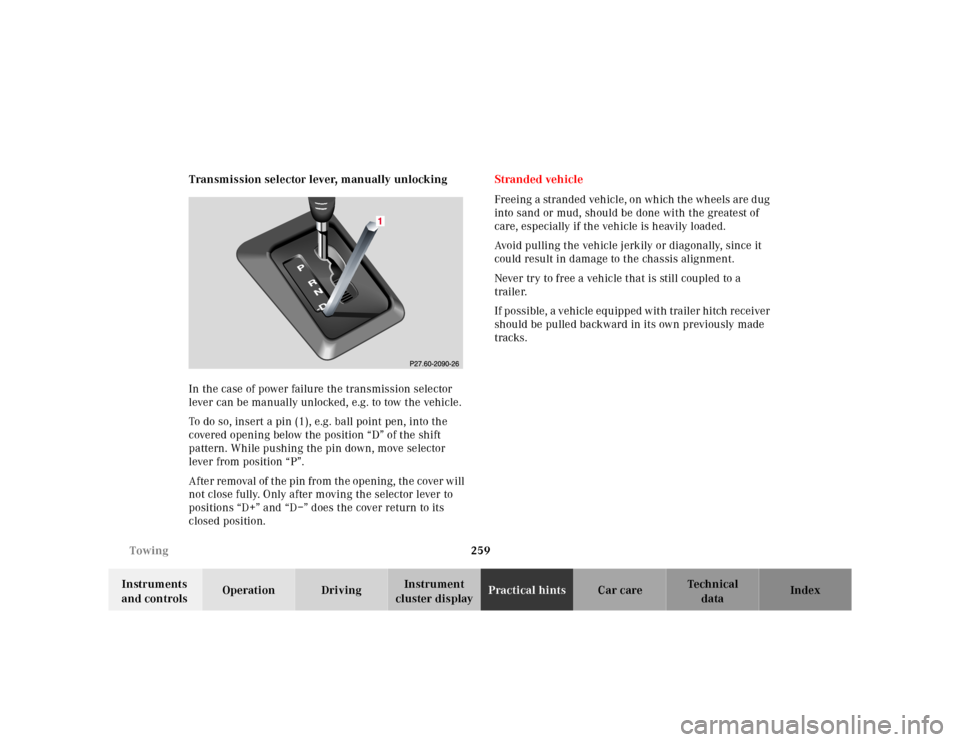
In the case of power failure the transmission selector
lever can be manually unlocked, e.g. to tow the vehicle.
To do so, insert a pin (1), e.g. ball point pen, into the
covered opening below the position “D” of the shift
pattern. While pushing the pin down, move selector
lever from position “P”.
After removal of the pin from the opening, the cover will
not close fully. Only after moving the selector lever to
positions “D+” and “D–” does the cover return to its
closed position.Stranded vehicle
Freeing a stranded vehicle, on which the wheels are dug
into sand or mud, should be done with the greatest of
care, especially if the vehicle is heavily loaded.
Avoid pulling the vehicle jerkily or diagonally, since it
could result in damage to the chassis alignment.
Never try to free a vehicle that is still coupled to a
trailer.
If possible, a vehicle equipped with trailer hitch receiver
should be pulled backward in its own previously made
tracks.
Page 290 of 317
287 Technical data
Te ch n ica l
data Instruments
and controlsOperation DrivingInstrument
cluster displayPractical hints Car care Index Technical data
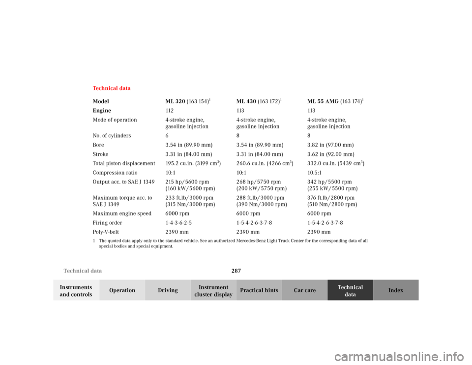
Model ML 320 (163 154)
1
ML 430 (163 172)
1
ML 55 AMG (163 174)
1
Engine112 113 113
Mode of operation 4-stroke engine,
gasoline injection4-stroke engine,
gasoline injection4-stroke engine,
gasoline injection
No. of cylinders688
Bore 3.54 in (89.90 mm) 3.54 in (89.90 mm) 3.82 in (97.00 mm)
Stroke 3.31 in (84.00 mm) 3.31 in (84.00 mm) 3.62 in (92.00 mm)
Total piston displacement 195.2 cu.in. (3199 cm
3) 260.6 cu.in. (4266 cm
3) 332.0 cu.in. (5439 cm
3)
Compression ratio 10:1 10:1 10.5:1
Output acc. to SAE J 1349 215 hp / 5600 rpm
(160 kW / 5600 rpm)268 hp / 5750 rpm
(200 kW / 5750 rpm)342 hp / 5500 rpm
(255 kW / 5500 rpm)
Maximum torque acc. to
SAE J 1349233 ft.lb / 3000 rpm
(315 Nm / 3000 rpm)288 ft.lb / 3000 rpm
(390 Nm / 3000 rpm)376 ft.lb / 2800 rpm
( 510 N m / 2 80 0 r p m )
Maximum engine speed 6000 rpm 6000 rpm 6000 rpm
Firing order 1-4-3-6-2-5 1-5-4-2-6-3-7-8 1-5-4-2-6-3-7-8
Poly-V-belt 2390 mm 2390 mm 2390 mm
1 The quoted data apply only to the standard vehicle. See an authorized Mercedes-Benz Light Truck Center for the corresponding data of all
special bodies and special equipment.