Page 222 of 317
219 Malfunction and indicator lamps
Te ch n ica l
data Instruments
and controlsOperation DrivingInstrument
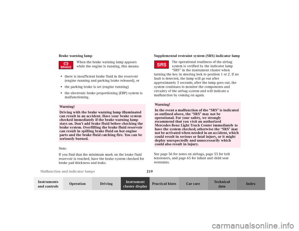
cluster displayPractical hints Car care Index Brake warning lamp
When the brake warning lamp appears
while the engine is running, this means:
•there is insufficient brake fluid in the reservoir
(engine running and parking brake released), or
•the parking brake is set (engine running)
•the electronic brake proportioning (EBP) system is
malfunctioning.
Note:
If you find that the minimum mark on the brake fluid
reservoir is reached, have the brake system checked for
brake pad thickness and leaks.Supplemental restraint system (SRS) indicator lamp
The operational readiness of the airbag
system is verified by the indicator lamp
“SRS” in the instrument cluster when
turning the key in steering lock to position 1 or 2. If no
fault is detected, the lamp will go out after
approximately 5 seconds; after the lamp goes out, the
system continues to monitor the components and
circuitry of the airbag system and will indicate a
malfunction by coming on again.
See page 56 for notes on airbags, page 55 for belt
tensioners, and page 65 for infant and child seat
restraints.
Wa r n i n g !
Driving with the brake warning lamp illuminated
can result in an accident. Have your brake system
checked immediately if the brake warning lamp
stays on. Don’t add brake fluid before checking the
brake system. Overfilling the brake fluid reservoir
can result in spilling brake fluid on hot engine
parts and the brake fluid catching fire. You can be
seriously burned.BRAKE
Wa r n i n g !
In the event a malfunction of the “SRS” is indicated
as outlined above, the “SRS” may not be
operational. For your safety, we strongly
recommend that you visit an authorized
Mercedes-Benz Light Truck Center immediately to
have the system checked; otherwise the “SRS” may
not be activated when needed in an accident, which
could result in serious or fatal injury, or it might
deploy unexpectedly and unnecessarily which
could also result in injury.SRS
Page 225 of 317
222 Malfunction and indicator lamps
Te ch n ica l
data Instruments
and controlsOperation DrivingInstrument
cluster displayPractical hints Car care Index
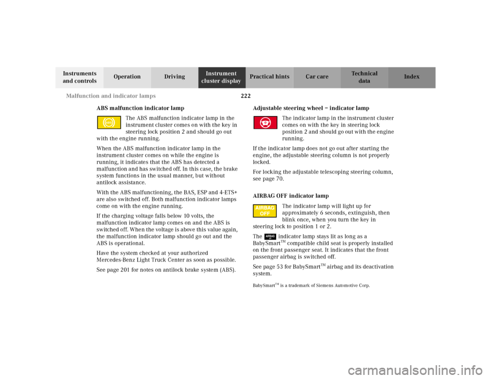
ABS malfunction indicator lamp
The ABS malfunction indicator lamp in the
instrument cluster comes on with the key in
steering lock position 2 and should go out
with the engine running.
When the ABS malfunction indicator lamp in the
instrument cluster comes on while the engine is
running, it indicates that the ABS has detected a
malfunction and has switched off. In this case, the brake
system functions in the usual manner, but without
antilock assistance.
With the ABS malfunctioning, the BAS, ESP and 4-ETS+
are also switched off. Both malfunction indicator lamps
come on with the engine running.
If the charging voltage falls below 10 volts, the
malfunction indicator lamp comes on and the ABS is
switched off. When the voltage is above this value again,
the malfunction indicator lamp should go out and the
ABS is operational.
Have the system checked at your authorized
Mercedes-Benz Light Truck Center as soon as possible.
See page 201 for notes on antilock brake system (ABS).Adjustable steering wheel – indicator lamp
The indicator lamp in the instrument cluster
comes on with the key in steering lock
position 2 and should go out with the engine
running.
If the indicator lamp does not go out after starting the
engine, the adjustable steering column is not properly
locked.
For locking the adjustable telescoping steering column,
see page 70.
AIRBAG OFF indicator lamp
The indicator lamp will light up for
approximately 6 seconds, extinguish, then
blink once, when you turn the key in
steering lock to position 1 or 2.
The 7 indicator lamp stays lit as long as a
BabySmart
TM compatible child seat is properly installed
on the front passenger seat. It indicates that the front
passenger airbag is switched off.
See page 53 for BabySmart
TM airbag and its deactivation
system.
BabySmart
TM is a trademark of Siemens Automotive Corp.
ABS
Page 226 of 317
223 Malfunction and indicator lamps
Te ch n ica l
data Instruments
and controlsOperation DrivingInstrument
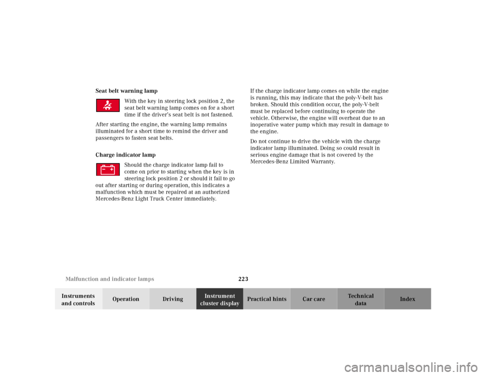
cluster displayPractical hints Car care Index Seat belt warning lamp
With the key in steering lock position 2, the
seat belt warning lamp comes on for a short
time if the driver’s seat belt is not fastened.
After starting the engine, the warning lamp remains
illuminated for a short time to remind the driver and
passengers to fasten seat belts.
Charge indicator lamp
Should the charge indicator lamp fail to
come on prior to starting when the key is in
steering lock position 2 or should it fail to go
out after starting or during operation, this indicates a
malfunction which must be repaired at an authorized
Mercedes-Benz Light Truck Center immediately.If the charge indicator lamp comes on while the engine
is running, this may indicate that the poly-V-belt has
broken. Should this condition occur, the poly-V-belt
must be replaced before continuing to operate the
vehicle. Otherwise, the engine will overheat due to an
inoperative water pump which may result in damage to
the engine.
Do not continue to drive the vehicle with the charge
indicator lamp illuminated. Doing so could result in
serious engine damage that is not covered by the
Mercedes-Benz Limited Warranty.
Page 240 of 317
237 Windshield wiper
Te ch n ica l
data Instruments
and controlsOperation DrivingInstrument
cluster displayPractical hintsCar care Index Windshield and headlamp washer
fluid mixing ratio
For temperatures above freezing:
MB Windshield Washer Concentrate “S” and water
1 part “S” to 100 parts water
(40 ml “S” to 1 gallon water).
For temperature below freezing:
MB Windshield Washer Concentrate “S” and
commercially available premixed windshield washer
solvent / antifreeze
1 part “S” to 100 parts solvent
(40 ml “S” to 1 gallon solvent).Vehicle jack, wheel bolt wrench and screwdriver
Wa r n i n g !
The jack is designed exclusively for jacking up the
vehicle at the jack take-up brackets built into either
side of the vehicle. To help avoid personal injury,
use the jack only to lift the vehicle during a wheel
change. Never get beneath the vehicle while it is
supported by the jack. Keep hands and feet away
from the area under the lifted vehicle. Always
firmly set parking brake and block wheels before
raising vehicle with jack.Do not disengage parking brake while the vehicle is
raised. Be certain that the jack is always vertical
when in use, especially on hills. Always try to use
the jack on level surface. Be sure that the jack arm
end is fully seated in the jack take-up bracket.
Always lower the vehicle onto sufficient capacity
jackstands before working under the vehicle.
Page 248 of 317
245 Tires, Wheels
Te ch n ica l
data Instruments
and controlsOperation DrivingInstrument
cluster displayPractical hintsCar care Index Changing wheels
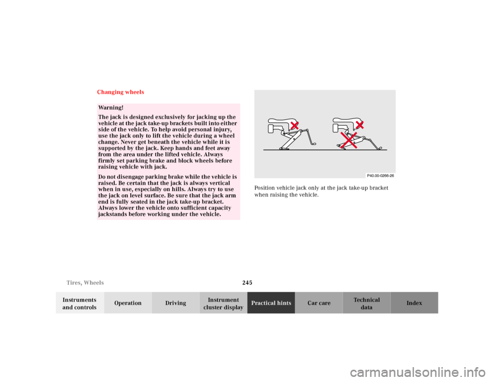
Position vehicle jack only at the jack take-up bracket
when raising the vehicle.
Wa r n i n g !
The jack is designed exclusively for jacking up the
veh icle at the jack take-u p brackets bu ilt i nto eit her
side of the vehicle. To help avoid personal injury,
use the jack only to lift the vehicle during a wheel
change. Never get beneath the vehicle while it is
supported by the jack. Keep hands and feet away
from the area under the lifted vehicle. Always
firmly set parking brake and block wheels before
raising vehicle with jack.Do not disengage parking brake while the vehicle is
raised. Be certain that the jack is always vertical
when in use, especially on hills. Always try to use
the jack on level surface. Be sure that the jack arm
end is fully seated in the jack take-up bracket.
Always lower the vehicle onto sufficient capacity
jackstands before working under the vehicle.
Page 250 of 317
247 Tires, Wheels
Te ch n ica l
data Instruments
and controlsOperation DrivingInstrument
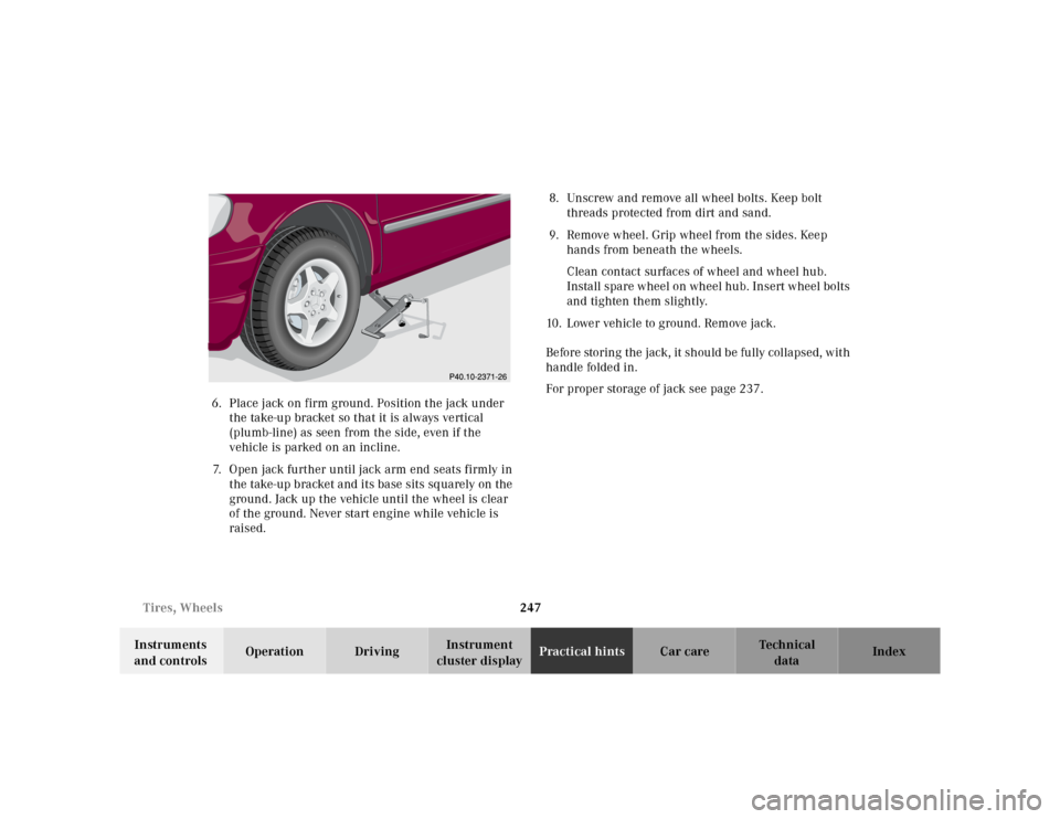
cluster displayPractical hintsCar care Index 6. Place jack on firm ground. Position the jack under
t he take-up bracket so t hat it is always ve rtical
(plumb-line) as seen from the side, even if the
vehicle is parked on an incline.
7. Open jack further until jack arm end seats firmly in
the take-up bracket and its base sits sq uarely on the
ground. Jack up the vehicle until the wheel is clear
of the ground. Never start engine while vehicle is
raised.8. Unscrew and remove all wheel bolts. Keep bolt
threads protected from dirt and sand.
9. Remove wheel. Grip wheel from the sides. Keep
hands from beneath the wheels.
Clean contact surfaces of wheel and wheel hub.
Install spare wheel on wheel hub. Insert wheel bolts
and tighten them slightly.
10. Lower vehicle to ground. Remove jack.
Before storing the jack, it should be fully collapsed, with
handle folded in.
For proper storage of jack see page 237.
Page 266 of 317
263 Exterior lamps
Te ch n ica l
data Instruments
and controlsOperation DrivingInstrument
cluster displayPractical hintsCar care Index Bulbs for high beam (only Halogen headlamps)
H1 U (55 W)
Bulbs for low beam
H7 (55 W)
Open hood.
Push down tab at top end of cover (3) and remove. Pull
off electrical connector (5 or 6). Unhook and move aside
clamping ring. Remove bulb.
Insert new bulb (seating properly in cutouts of bulb
socket), mount clamping ring. Reinstall and push
electrical connector on securely. Reinstall cover (3).Xenon (optional)
Bulb for low beam
Xenon (optional)
Bulb for high beam
Note:
Vehicles with Xenon headlamps:
We recommend that you have changed the bulb for the
high beam by a qualified technician.
Wa r n i n g !
Because of high voltage in Xenon lamps, it is
dangerous to replace the bulb or repair the lamp
and its components. We recommend that you have
such work done by a qualified technician.
Page 267 of 317
264 Exterior lamps
Te ch n ica l
data Instruments
and controlsOperation DrivingInstrument
cluster displayPractical hintsCar care Index
Parking, standing, side marker and turn signal lamp
115 6 N A ( 3 2 / 4 c p b u l b )
Open hood.
Twist bulb socket (4) counterclockwise and pull out.
Push bulb into socket, turn counterclockwise and
remove.
Insert new bulb in socket, push in and twist clockwise.
Reinstall bulb socket.Bulbs for auxiliary fog lamp (optional)
H3 U (55 W)
Open hood.
Remove cover (9). Unhook clamping ring and remove
bulb. Pull off electrical connector.
Insert new bulb in socket (seating properly in cutouts of
bulb socket), and mount clamping ring. Reinstall and
push electrical connector on securely.
Reinstall cover (9).