Page 136 of 317
133 Interior equipment
Te ch n ica l
data Instruments
and controlsOperationDrivingInstrument
cluster displayPractical hints Car care Index Hooks
Four hooks, located on the rear compartment trim
panels can be used to secure light weight items
(maximum permissible weight per hook: 9 lbs. [4 kg]).Partiti on net (Optional)
Use of the partition net is a particularly important safety
factor when the vehicle is loaded higher than the top of
the seat backrests with smaller objects.
The partition net can be installed behind the backrests
of the front or rear seats.
Note:
Passenger use of seats behind installed partition net is
restricted because of the footwell being taken up by the
net.
Page 137 of 317
134 Interior equipment
Te ch n ica l
data Instruments
and controlsOperationDrivingInstrument
cluster displayPractical hints Car care Index
Installation:
1. Engage partition net in holders (1) and close rear
cover.2. Insert tie down hooks (2) in rings (3) behind the
front seats.
3. Pull on loose ends of tie downs until net is tight.
For installation behind the rear seats, see next page.
Page 138 of 317
135 Interior equipment
Te ch n ica l
data Instruments
and controlsOperationDrivingInstrument
cluster displayPractical hints Car care Index Installation behind rear seats
1. Insert tie down hooks (2) in rings (3) behind the
rear seats.
2. Pull on loose ends of tie downs until net is tight.Removal:
1. Lift tensioner (4) upward to a horizontal position to
release tensioning of the strap.
2. Disengage tie down hooks (2) from rings (3).
3. Remove partition net from holders (1) and close the
covers.
Storage:
1. Roll up and close partition net.
2. Store partition net behind rear seat bench.
Caution!
While the partition net will help protect you from
smaller objects, it cannot prevent the movement of
large, heavier objects into the passenger area in an
accident. Such items must be properly secured using
the cargo tie-down rings in the cargo area floor, see
page 132.
Page 139 of 317

136 Interior equipment
Te ch n ica l
data Instruments
and controlsOperationDrivingInstrument
cluster displayPractical hints Car care Index
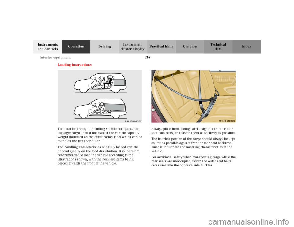
Loading instructions
The total load weight including vehicle occupants and
luggage / cargo should not exceed the vehicle capacity
weight indicated on the certification label which can be
found on the left door pillar.
The handling characteristics of a fully loaded vehicle
depend greatly on the load distribution. It is therefore
recommended to load the vehicle according to the
illustrations shown, with the heaviest items being
placed towards the front of the vehicle.Always place items being carried against front or rear
seat backrests, and fasten them as securely as possible.
The heaviest portion of the cargo should always be kept
as low as possible against front or rear seat backrest
since it influences the handling characteristics of the
vehicle.
For additional safety when transporting cargo while the
rear seats are unoccupied, fasten the outer seat belts
crosswise into the opposite side buckles.
Page 141 of 317
138 Interior equipment
Te ch n ica l
data Instruments
and controlsOperationDrivingInstrument
cluster displayPractical hints Car care Index
Removing blind:
Pull right side mounting sleeve toward vehicle center
(arrow) until button (1) engages, and remove blind from
holders.Installing blind:
Place left side of blind in left mount. Position right side
of blind over right mount. Push button (1), releasing
mounting sleeve to slide into mount.
Notes:
A removable cap is fitted into the mount openings on
vehicles fitted with third row seats.
Passenger use of third row seats with cargo area cover
blind installed is restricted.
2
Page 162 of 317

159 Tele Aid
Te ch n ica l
data Instruments
and controlsOperationDrivingInstrument
cluster displayPractical hints Car care Index Info Services (optional, except Canada)
Info Services categories include news, sports, stocks,
weather and calendar reminders. Choices can be
selected via www.mbusa.com or by calling 1-800-FOR-
MERcedes.
To request Info Services press the TEL button and then
the SVC soft key on the MCS unit. Then select UPDT
soft key. “NEW INFO SERVICE REQUEST
TRANSMITTED” will appear in the MCS display and call
status messages will appear in the MCS display.
Once information is available, the message “NEW INFO
RECEIVED READ LATER WHEN STOPPED?” will appear.
Select “Yes”. With the vehicle stopped in a safe location
press TEL button, SVC soft key to read messages.Important!
Tele Aid utilizes the cellular network for
communication and the GPS (Global Positioning
System) satellites for vehicle location. If either of these
signals are unavailable, the Tele Aid system may not
function and if this occurs, assistance must be
summoned by other means.
Wa r n i n g !
The Tele Aid control unit is located under the front
passenger seat. If there is accumulation of water or
other liquid in this area, the Tele Aid control unit
could suffer an electrical short circuit making the
system inoperative. In this case the indicator lamp
in the “SOS” button will not illuminate during or
will remain illuminated after the system self-check.
Have the system checked at the nearest
Mercedes-Benz Light Truck Center as soon as
possible.
Page 166 of 317
163 Steering lock
Te ch n ica l
data Instruments
and controlsOperationDrivingInstrument
cluster displayPractical hints Car care Index Caution!
To prevent accelerated battery discharge and a possible
dead battery, always remove the key from the steering
lock. Do not leave the key in steering lock position 0.
Notes:
A warning sounds when the driver’s door is opened
while the key is in steering lock position 1 or 0.
With the engine at idle speed, the charging rate of the
alternator (output) is limited.It is therefore recommended that you turn off
unnecessary electrical consumers while driving in stop-
and-go traffic. This precaution helps to avoid draining of
the battery.
Unnecessary strain on the battery and charging system
may be minimized by turning off the following power
consumers, for example: Heated seats, rear window
defroster.
Page 220 of 317

217 Contents - Instrument cluster display
Te ch n ica l
data Instruments
and controlsOperation DrivingInstrument
cluster displayPractical hints Car care Index
Instrument cluster displayMalfunction and indicator
lamps in the
instrument cluster .................... 218
On-board diagnostic system –
Check engine malfunction
indicator lamp ............................. 218
Brake warning lamp .................. 219
Supplemental restraint system
(SRS) indicator lamp .................. 219
Fuel reserve warning .................220Electronic stability
program (ESP) / Electronic
traction system (ETS) –
warning lamp ............................. 221
BAS/ESP malfunction
indicator lamp ............................ 221
4-ETS malfunction
indicator lamp ............................ 221
LOW RANGE
indicator lamp ............................ 221
ABS malfunction
indicator lamp ............................ 222Adjustable steering wheel –
indicator lamp .............................222
AIRBAG OFF
indicator lamp .............................222
Seat belt warning lamp .............223
Charge indicator lamp ...............223
Low engine oil level
warning lamp ..............................224
Low engine coolant
level warning ..............................224
Brake pad wear
indicator lamp .............................225
FSS indicator ...............................225