Page 247 of 317
244 Tires, Wheels
Te ch n ica l
data Instruments
and controlsOperation DrivingInstrument
cluster displayPractical hintsCar care Index
2. Loosen screw (2) using wrench supplied with
vehicle tools, see page 237. The screw (2) remains
in the holder.
3. Lift spare wheel carrier slightly and push lever (3)
to the right using screwdriver supplied with vehicle
tools, swing spare wheel carrier down and pull it out
from under the bumper.
4. Remove space-saver spare wheel.
Page 250 of 317
247 Tires, Wheels
Te ch n ica l
data Instruments
and controlsOperation DrivingInstrument
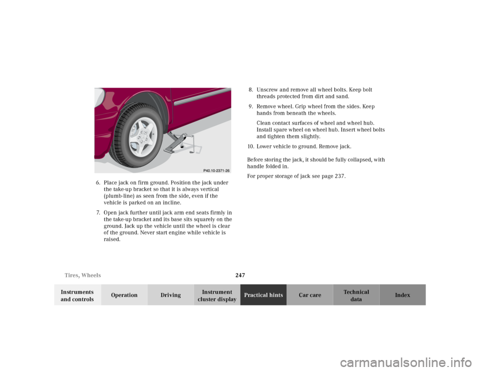
cluster displayPractical hintsCar care Index 6. Place jack on firm ground. Position the jack under
t he take-up bracket so t hat it is always ve rtical
(plumb-line) as seen from the side, even if the
vehicle is parked on an incline.
7. Open jack further until jack arm end seats firmly in
the take-up bracket and its base sits sq uarely on the
ground. Jack up the vehicle until the wheel is clear
of the ground. Never start engine while vehicle is
raised.8. Unscrew and remove all wheel bolts. Keep bolt
threads protected from dirt and sand.
9. Remove wheel. Grip wheel from the sides. Keep
hands from beneath the wheels.
Clean contact surfaces of wheel and wheel hub.
Install spare wheel on wheel hub. Insert wheel bolts
and tighten them slightly.
10. Lower vehicle to ground. Remove jack.
Before storing the jack, it should be fully collapsed, with
handle folded in.
For proper storage of jack see page 237.
Page 253 of 317
250 Tires, Wheels
Te ch n ica l
data Instruments
and controlsOperation DrivingInstrument
cluster displayPractical hintsCar care Index
Tire inflation pressure
A table (see fuel filler flap) lists the tire inflation
pressures specified for Mercedes-Benz recommended
tires as well as for the varying operating conditions.
Important!
Tire pressure changes by approximately 1.5 psi (0.1 bar)
per 18°F (10°C) of air temperature change. Keep this in
mind when checking tire pressure inside a garage –
especially in the winter.
Example:
If garage temperature = approximately +68°F (+20°C)
and ambient temperature = approximately +32°F (0°C)
then the adjusted air pressure = specified air pressure
+3 psi (+0.2 bar).Tire pressures listed for light loads are minimum values
offering high driving comfort. Increased inflation
pressures for heavy loads produce favorable handling
characteristics with lighter loads and are perfectly
permissible. The ride of the vehicle, however, will
become somewhat harder.
Tire temperature and pressure increase with the vehicle
speed. Tire pressure should therefore only be checked
and corrected on cold tires. Correct tire pressure in
warm tires only if pressure has dropped below the
pressure listed in the table and the respective operating
conditions are taken into consideration.
An underinf lated tire due to a slow leak (e.g. due to a
nail in the tire) may cause damage such as tread
separation, bulging etc.. Regular tire pressure checks
(including the spare tire) at intervals of no more than
14 days are therefore essential.
Page 257 of 317
254 Jump starting
Te ch n ica l
data Instruments
and controlsOperation DrivingInstrument
cluster displayPractical hintsCar care Index
Proceed as follows:
1. Position the vehicle with the charged battery so that
the jumper cables will reach, but never let the
vehicles touch. Make sure the jumper cables do not
have loose or missing insulation.
2. On both vehicles:
•Turn off engine and all lights and accessories,
except hazard warning flashers or work lights.
•Apply parking brake and shift selector lever to
position “P”.
Important!
3. Clamp one end of the first jumper cable to the
positive (+) under hood terminal of the discharged
battery and the other end to the positive (+) terminal
of the charged battery. Make sure the cable clamps
do not touch any other metal parts.
4. Clamp one end of the second jumper cable to the
grounded negative (–) terminal of the charged
battery and the final connection to the negative (–)
terminal of the discharged battery.Important!
5. Start engine of the vehicle with the charged battery
and run at high idle. Make sure the cables are not
on or near pulleys, fans, or other parts that move
when the engine is started. Allow the discharged
battery to charge for a few minutes. Start engine of
the disabled vehicle in the usual manner.
6. After the engine has started, remove jumper cables
by exactly reversing the above installation
sequence, starting with the last connection made
first. When removing each clamp, make sure that it
does not touch any other metal while the other end
is still attached.
Notes:
If engine does not run after several unsuccessful
starting attempts, have it checked at the nearest
authorized Mercedes-Benz Light Truck Center.
Excessive unburned fuel may damage the catalytic
converter.
Page 269 of 317
266 Exterior lamps
Te ch n ica l
data Instruments
and controlsOperation DrivingInstrument
cluster displayPractical hintsCar care Index
Pull off electrical connector (2).
Squeeze tabs (3) together and remove bulb holder.
Push bulb into socket, turn counterclockwise and
remove.
Insert new bulb in socket, push in and twist clockwise.
Reinstall bulb holder.
Reinstall electrical connector (2).
Reinstall taillamp.Turn signal lamp, side (168 [3 cp bulb])
Carefully slide lamp slightly towards rear (arrow), lift
away its front end first, then remove lamp from panel.
Twist bulb socket counterclockwise and pull out. Pull
bulb out of socket.
Insert new bulb in socket. Reinstall bulb socket.
To reinstall lamp, set rear end of lamp into panel and let
front end snap into place.
Page 271 of 317
268 Exterior lamps
Te ch n ica l
data Instruments
and controlsOperation DrivingInstrument
cluster displayPractical hintsCar care Index
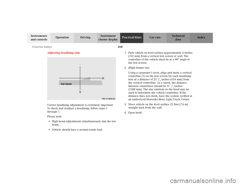
Adjusting headlamp aim
Correct headlamp adjustment is extremely important.
To check and readjust a headlamp, follow steps 1
through 7.
Please note:
•High beam adjustments simultaneously aim the low
beam.
•Vehicle should have a normal trunk load.1. Park vehicle on level surface approximately 6 inches
(152 mm) from a vertical test screen or wall. The
centerline of the vehicle must be at a 90° angle to
the test screen.
2. (High beams on):
Using a carpenter’s level, align and mark a vertical
centerline (1) on the test screen for each headlamp
lens at a distance of 25
3/4inches (654 mm) from
the vertical centerline. As a check, the distance
between centerlines should be 51
1/2inches
(1308 mm). The star emblem on the hood may be
used to determine the vehicle centerline. If the
distance does not check, have the system verified at
an authorized Mercedes-Benz Light Truck Center.
3. Move vehicle on the level surface 25 feet (7.6 m)
straight back from the wall.
4. Open hood.
VH
low beam
Page 272 of 317
269 Exterior lamps
Te ch n ica l
data Instruments
and controlsOperation DrivingInstrument
cluster displayPractical hintsCar care Index 5. (High beams on):
Simultaneously turn adjusting screws (1 and 2 on
page 261 or 262) counterclockwise to adjust
headlamp downward, clockwise upward) equally
until bubble in the level (7 on page 261) is centered
on the “0” mark.
Graduations:
screw 1: 0.50° pitch,
screw 2: 0.67° pitch.
6. Horizontal headlamp aim (High beams on):
Turn adjusting screw (2) (left headlamp:
counterclockwise to adjust to the left, clockwise to
the right [right headlamp in opposite direction])
until the headlamp (high beam pattern) is centered
about the vertical centerline (1) as shown.
The left and right headlamps must be adjusted
individually.7. For proper aim, the indicator (8 on page 261) should
align with the “0” mark after horizontal adjustment.
Graduations: 0.33° pitch.
Note:
If it is not possible to obtain a proper headlamp
adjustment, have the system checked at your authorized
Mercedes-Benz Light Truck Center.
Page 274 of 317
271 Remote control
Te ch n ica l
data Instruments
and controlsOperation DrivingInstrument
cluster displayPractical hintsCar care Index Synchronizing remote control
If the remote control does not function correctly and the
batteries are in order, the system may have to be
resynchronized.
Turn key in steering lock to position 2, then to
position 0 and remove.
Within 10 seconds, push and hold button‹ while
pushing buttonΠfive times.
Release the button, and press‹, Œ orŠ once.
Check all functions. The remote control should once
again be operational.
Note:
If it is not possible to resynchronize the remote control,
have the system checked at your authorized Mercedes-
Benz Light Truck Center.Important!
Batteries contain materials that can harm the
environment if disposed of improperly. Recycling of
batteries is the preferred method of disposal. For
disposal, please follow manufacturer’s recommendation
on battery package.
Replacement Battery:
Lithium, type CR 2025 or equivalent.