2001 MERCEDES-BENZ E-Class WAGON spare tire
[x] Cancel search: spare tirePage 7 of 345

4 Contents
AIRBAG OFF
indicator lamp .............................246
Malfunction and warning
messages in the
multifunction display ............... 247
DISPLAY DEFECTIVE ................248
BATTERY / ALTERNATOR .........249
ABS-SYSTEM ...............................250
BRAKE ASSIST ...........................250
BRAKE LINING WEAR .............. 251
BRAKE FLUID ............................. 251
PARKING BRAKE .......................252
ENGINE FAN ...............................252
COOLANT (coolant level) ..........253
COOLANT TEMP. (coolant
temperature) ...............................254
LIGHTING SYSTEM ....................255
LIGHT SENSOR ...........................256
REMOVE KEY .............................256
TELE AID .....................................257
STEERING GEAR OIL .................257
ENGINE OIL LEVEL ...................258
WASHER FLUID ..........................259ELEC. STABIL. PROG.
(Electronic stability program) . 260
Practical hintsFirst aid kit ..................................... 262
Fuses ............................................... 263
Electrical outlet.............................. 265
Hood ................................................ 266
Checking engine oil level............. 268
Automatic transmission
fluid level ................................... 269
Coolant level................................... 269
Adding coolant ........................... 270
Windshield and headlamp
washer system .......................... 271
Windshield and headlamp
washer fluid mixing ratio .........271
Spare wheel, vehicle tools............ 272
Vehicle jack .................................... 273
Wheels ............................................ 274
Tire replacement ........................274
Rotating wheels ......................... 275
Spare wheel..................................... 276
Spare wheel bolts .......................276Changing wheels ........................... 277
Tire inflation pressure .................. 282
Battery ............................................. 283
Jump starting .................................. 285
Towing the vehicle ......................... 288
Transmission selector lever,
manually unlocking .................. 290
Exterior lamps ................................ 291
Headlamp assembly ...................292
Taillamp assemblies ..................295
Changing batteries in the
electronic main key .................. 298
Synchronizing
remote control ............................300
Emergency engine
shut-down................................... 300
Emergency operation of
sliding / pop-up roof ................. 301
Manual release for
fuel filler flap ............................. 302
Replacing wiper blade insert ....... 302
Roof rack ......................................... 305
Page 193 of 345
190 Tele Aid
Te ch n ica l
data Instruments
and controlsOperationDrivingInstrument
cluster displayPractical hints Car care Index
Roadside Assistance button •
Located below the center armrest cover is the Roadside
Assistance button•. Pressing and holding the
button (for longer than 2 seconds) will initiate a call to a
Mercedes-Benz Roadside Assistance dispatcher. The
button will flash while the call is in progress. The
message “ROADSIDE ASSISTANCE – CONNECTING
CALL” will appear in the multifunction display. When
the connection is established, the message “ROADSIDE
ASSISTANCE – CALL CONNECTED” appears in the
multifunction display. The Tele Aid system will transmit
data generating the vehicle identification number,
model, color and location (subject to availability of
cellular and GPS signals).
A voice connection between the Roadside Assistance
dispatcher and the occupants of the vehicle will be
established. When a voice connection is established the
audio system mutes and the message “TELE AID –
ROADSIDE ASSISTANCE CALL ACTIVE” appears in the
multifunction display. The nature of the need for
assistance can then be described. The Mercedes-Benz
Roadside assistance dispatcher will either dispatch a
qualified Mercedes-Benz technician or arrange to tow
your vehicle to the nearest Mercedes-Benz Center. For services such as labor and/or towing charges may
apply. Refer to the Roadside Assistance manual for more
information.
These programs are only available in the USA:
•Sign and Drive services: Services such as jump start,
a few gallons of fuel or the replacement of a f lat tire
with the vehicle spare tire are obtainable,
•Remote Vehicle Diagnostics: This function permits
the Mercedes-Benz Roadside Assistance dispatcher
to download malfunction codes and actual vehicle
data.
Notes:
The indicator lamp in the Roadside Assistance
button• remains illuminated in red for approx.
10 seconds during the system self-check after turning
electronic key in starter switch to position 2 (together
with the “SOS” button and the Information
button¡).
See system self-check on page 186 when the indicator
lamp does not light up in red or stays on longer than
approximately 10 seconds.
Page 232 of 345
229 Driving systems
Te ch n ica l
data Instruments
and controlsOperationDrivingInstrument
cluster displayPractical hints Car care Index Notes:
The malfunction indicator lamp for the ESP is combined
with that of the BAS.
The yellow BAS / ESP malfunction indicator lamp in the
instrument cluster and the yellow ESP warning
lampv in the speedometer dial come on with the
electronic key in steering lock position 2. They should
go out with the engine running.
If the BAS / ESP malfunction indicator lamp comes on
continuously with the engine running, a malfunction
has been detected in either system. Only partial engine
output will be available.
If the BAS malfunctions, the brake system functions in
the usual manner, but without BAS.
If the ESP warning message is displayed, have the BAS
or ESP checked at your authorized Mercedes-Benz
Center as soon as possible.
With the ABS malfunctioning, the ESP is also switched
off.Driving the vehicle with varied size tires will cause the
wheels to rotate at different speeds, therefore the ESP
may activate (yellow ESP warning lamp in speedometer
dial comes on). For this reason, all wheels, including the
spare wheel, must have the same tire size.
When testing the parking brake on a brake test
dynamometer, the engine must be shut off. Otherwise,
the ESP will immediately be engaged and will apply the
rear wheel brakes.
In winter operation, the maximum effectiveness of the
ESP is only achieved with Mercedes-Benz recommended
M+S rated radial-ply tires and / or snow chains.
Synchronizing ESP
If the power supply was interrupted (battery
disconnected or empty), the BAS / ESP malfunction
indicator lamp may be illuminated with the engine
running.
Turn steering wheel completely to the left and then to
the right. The BAS / ESP malfunction indicator lamp
should go out.
Page 264 of 345

261 Contents - Practical hints
Te ch n ica l
data Instruments
and controlsOperation DrivingInstrument
cluster displayPractical hintsCar care Index
Practical hintsFirst aid kit...................................... 262
Fuses ................................................ 263
Electrical outlet .............................. 265
Hood ................................................. 266
Checking engine oil level ............. 268
Automatic transmission
fluid level ................................... 269
Coolant level ................................... 269
Adding coolant ...........................270
Windshield and headlamp
washer system ........................... 271
Windshield and headlamp
washer fluid mixing ratio ......... 271Spare wheel, vehicle tools............ 272
Vehicle jack .................................... 273
Wheels ............................................ 274
Tire replacement ........................274
Rotating wheels ......................... 275
Spare wheel..................................... 276
Spare wheel bolts .......................276
Changing wheels........................... 277
Tire inflation pressure ................. 282
Battery............................................. 283
Jump starting.................................. 285
Towing the vehicle ........................ 288
Transmission selector lever,
manually unlocking ................. 290Exterior lamps ................................ 291
Headlamp assembly ...................292
Taillamp assemblies ..................295
Changing batteries in the
electronic main key .................. 298
Synchronizing
remote control ............................300
Emergency engine
shut-down................................... 300
Emergency operation of
sliding / pop-up roof ................. 301
Manual release for
fuel filler flap ............................. 302
Replacing wiper blade insert ....... 302
Roof rack ......................................... 305
Page 279 of 345
276 Tires, Wheels
Te ch n ica l
data Instruments
and controlsOperation DrivingInstrument
cluster displayPractical hintsCar care Index
Spare wheel
Important!
Unidirectional tires must always be mounted with arrow
on tire sidewall pointing in direction of vehicle forward
movement.
If the arrow on tire side wall does not point in direction
of vehicle forward movement when using the spare
wheel, observe the following restrictions:
•Drive to the nearest tire repair facility as soon as
possible.
For rim and tire specifications, see page 320.
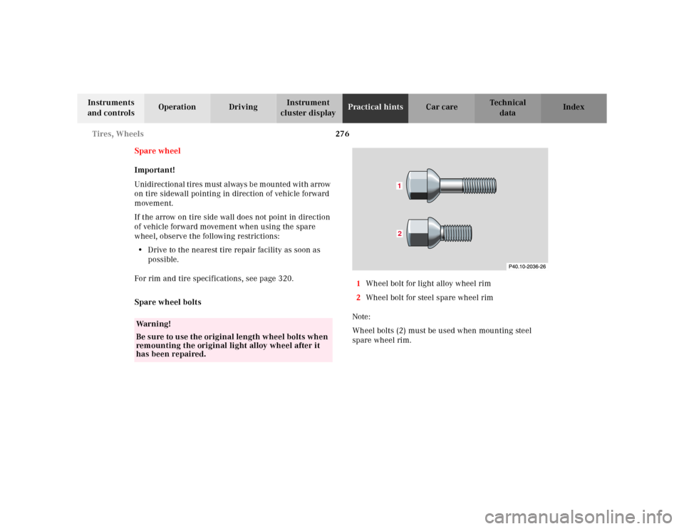
Spare wheel bolts1Wheel bolt for light alloy wheel rim
2Wheel bolt for steel spare wheel rim
Note:
Wheel bolts (2) must be used when mounting steel
spare wheel rim.
Wa r n i n g !
Be sure to use the original length wheel bolts when
remounting the original light alloy wheel after it
has been repaired.
12
Page 283 of 345
280 Tires, Wheels
Te ch n ica l
data Instruments
and controlsOperation DrivingInstrument
cluster displayPractical hintsCar care Index
Important!
When installing steel spare wheel rim, make certain to
use the correct wheel bolts, supplied in the vehicle tool
kit, see page 276 and page 272.10. Clean contact surfaces of wheel and wheel hub.
Install wheel on wheel hub. Insert wheel bolts and
tighten them slightly.
To avoid paint damage, place wheel f lat against hub
and hold it there while installing first wheel bolt.
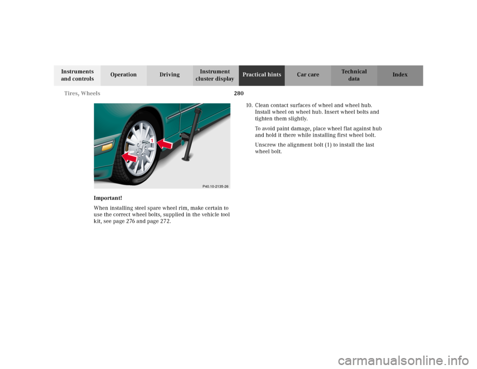
Unscrew the alignment bolt (1) to install the last
wheel bolt.
P40.10-2135-26
1
Page 285 of 345
282 Tires, Wheels
Te ch n ica l
data Instruments
and controlsOperation DrivingInstrument
cluster displayPractical hintsCar care Index
Tire inflation pressure
A table (see fuel filler flap) lists the tire inflation
pressures specified for Mercedes-Benz recommended
tires as well as for the varying operating conditions.
Important!
Tire pressure changes by approximately 1.5 psi (0.1 bar)
per 18°F (10°C) of air temperature change. Keep this in
mind when checking tire pressure inside a garage -
especially in the winter.
Example:
If garage temperature = approximately +68°F (+20°C)
and ambient temperature = approximately +32°F (0°C)
then the adjusted air pressure = specified air pressure
+3 psi (+0.2 bar).Tire pressures listed for light loads are minimum values
offering high driving comfort. Increased inflation
pressures for heavy loads produce favorable handling
characteristics with lighter loads and are perfectly
permissible. The ride of the vehicle, however, will
become somewhat harder.
Tire temperature and pressure increase with the vehicle
speed. Tire pressure should therefore only be checked
and corrected on cold tires. Correct tire pressure in
warm tires only if pressure has dropped below the
pressure listed in the table and the respective operating
conditions are taken into consideration.
An underinf lated tire due to a slow leak (e.g. due to a
nail in the tire) may cause damage such as tread
separation, bulging etc.. Regular tire pressure checks
(including the spare tire) at intervals of no more than
14 days are therefore essential.
Page 286 of 345
283 Battery
Te ch n ica l
data Instruments
and controlsOperation DrivingInstrument
cluster displayPractical hintsCar care Index If a tire constantly loses air, it should be inspected for
damage.
The spare tire should be checked periodically for
condition and inflation. Spare tire will age and become
worn over time even if never used, and thus should be
inspected and replaced when necessary.Battery
Important!
Battery replacement information:
The maintenance-free battery is located under the rear
seat cushion. To minimize the chance for acid leakage
which could cause severe burns during a crash or
rollover, a special acid leakage resistant battery was
factory installed. A replacement battery for the vehicle
Wa r n i n g !
Do not overinflate tires. Overinflating tires can
result in sudden deflation (blowout) because they
are more likely to become punctured or damaged
by road debris, potholes etc.. Follow recommended
inflation pressures.Do not overload the tires by exceeding the specified
vehicle capacity weight (as indicated by the label
on the driver’s door latch post). Overloading the
tires can overheat them, possibly causing a
blowout.
Wa r n i n g !
Failure to follow these instructions can result in
severe injury or death.Never lean over batteries while connecting, you
might get injured.Battery fluid contains sulfuric acid. Do not allow
this fluid to come in contact with eyes, skin or
clothing. In case it does, immediately flush affected
area with water and seek medical help if necessary.A battery will also produce hydrogen gas, which is
flammable and explosive. Keep flames or sparks
away from battery, avoid improper connection of
jumper cables, smoking etc..