Page 90 of 345
87 Instrument cluster
Te ch n ica l
data Instruments
and controlsOperationDrivingInstrument
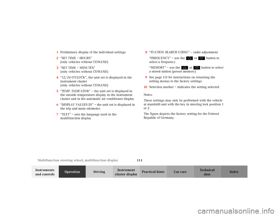
cluster displayPractical hints Car care Index 1Push buttons for intensity of instrument lamps,
see page 89
2Push button for resetting trip odometer, see page 91,
or to acknowledge a malfunction or warning
message, see page 108
3Coolant temperature gauge, see page 90
4Fuel gauge with reserve and fuel cap placement
warning lamp, see page 244
5Outside temperature indicator, see page 90
6Left turn signal indicator lamp, see combination
switch on page 122
7ESP (Electronic stability program) warning lamp,
see page 2458Speedometer
9Trip odometer, see page 91 and 96
10Main odometer, see page 96
11Multifunction display, see page 92 and 247
12Right turn signal indicator lamp, see combination
switch on page 122
13Tachometer, see page 91
14Gear range indicator display, see page 204
15Clock
To set the time, see page 110
Page 114 of 345

111 Multifunction steering wheel, multifunction display
Te ch n ica l
data Instruments
and controlsOperationDrivingInstrument
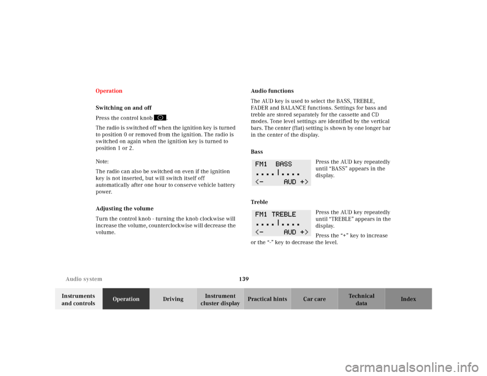
cluster displayPractical hints Car care Index 1Preliminary display of the individual settings
2“SET TIME – HOURS”
(only vehicles without COMAND)
3“SET TIME – MINUTES”
(only vehicles without COMAND)
4“12 / 24 O’CLOCK”, the unit set is displayed in the
instrument cluster
(only vehicles without COMAND)
5“TEMP. INDICATOR” — the unit set is displayed in
the outside temperature display in the instrument
cluster and in the automatic air conditioner display
6“DISPLAY VALUES IN” – the unit set is displayed in
the trip and main odometer.
7“TEXT” – sets the language used in the
multifunction display8“STATION SEARCH USING” — radio adjustment
“FREQUENCY” – use the j or k button to
select a frequency
“MEMORY” – use the j or k button to select
a stored station (preset memory)
9See page 113 for instructions on returning the
setting menus to the factory settings
10Selection marker – indicates the setting selected
Notes:
These settings may only be performed with the vehicle
at standstill and with the key in steering lock position 1
or 2.
The figure depicts the factory setting for the Federal
Republic of Germany.
Page 142 of 345

139 Audio system
Te ch n ica l
data Instruments
and controlsOperationDrivingInstrument
cluster displayPractical hints Car care Index Operation
Switching on and off
Press the control knob .
The radio is switched off when the ignition key is turned
to position 0 or removed from the ignition. The radio is
switched on again when the ignition key is turned to
position 1 or 2.
Note:
The radio can also be switched on even if the ignition
key is not inserted, but will switch itself off
automatically after one hour to conserve vehicle battery
power.
Adjusting the volume
Turn the control knob - turning the knob clockwise will
increase the volume, counterclockwise will decrease the
volume.Audio functions
The AUD key is used to select the BASS, TREBLE,
FADER and BALANCE functions. Settings for bass and
treble are stored separately for the cassette and CD
modes. Tone level settings are identified by the vertical
bars. The center (flat) setting is shown by one longer bar
in the center of the display.
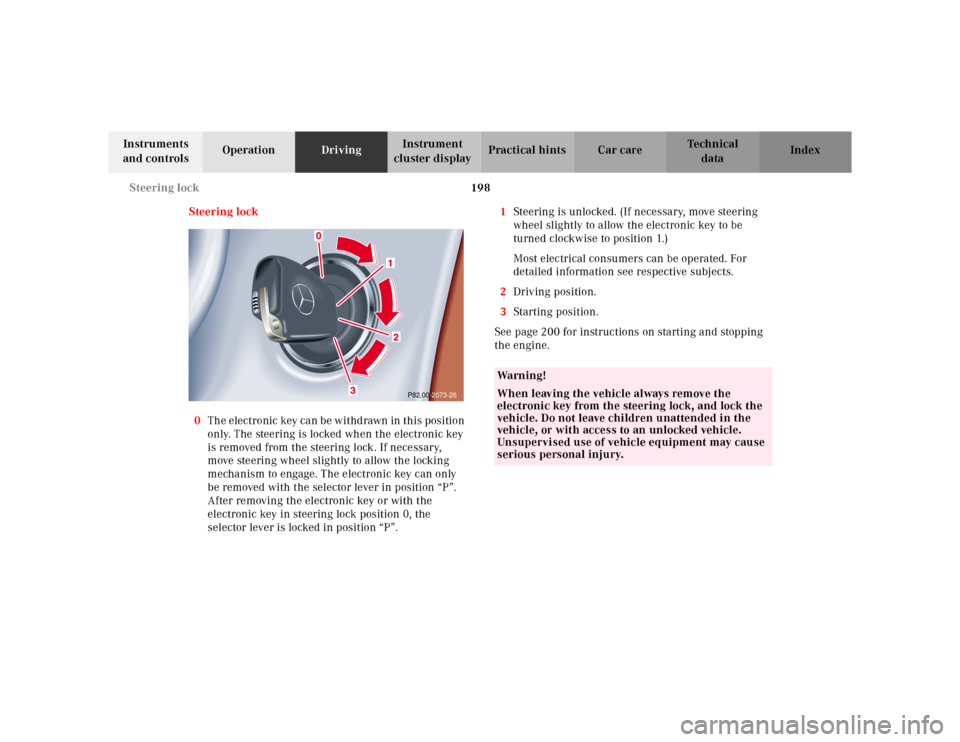
Bass
Press the AUD key repeatedly
until “BASS” appears in the
display.
Treble
Press the AUD key repeatedly
until “TREBLE” appears in the
display.
Press the “+” key to increase
or the “-” key to decrease the level.
Page 201 of 345

198 Steering lock
Te ch n ica l
data Instruments
and controlsOperationDrivingInstrument
cluster displayPractical hints Car care Index
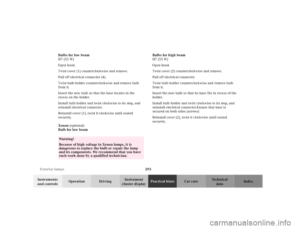
Steering lock
0The electronic key can be withdrawn in this position
only. The steering is locked when the electronic key
is removed from the steering lock. If necessary,
move steering wheel slightly to allow the locking
mechanism to engage. The electronic key can only
be removed with the selector lever in position “P”.
After removing the electronic key or with the
electronic key in steering lock position 0, the
selector lever is locked in position “P”.1Steering is unlocked. (If necessary, move steering
wheel slightly to allow the electronic key to be
turned clockwise to position 1.)
Most electrical consumers can be operated. For
detailed information see respective subjects.
2Driving position.
3Starting position.
See page 200 for instructions on starting and stopping
the engine.
P82.00-2073-26
Wa r n i n g !
When leaving the vehicle always remove the
electronic key from the steering lock, and lock the
vehicle. Do not leave children unattended in the
vehicle, or with access to an unlocked vehicle.
Unsupervised use of vehicle equipment may cause
serious personal injury.
Page 203 of 345

200 Starting and turning off the enging
Te ch n ica l
data Instruments
and controlsOperationDrivingInstrument
cluster displayPractical hints Car care Index
Starting and turning off the engine
Before Starting
Ensure that parking brake is engaged and that selector
lever is in position “P” or “N”. Turn electronic key in
steering lock to position 2.
Starting
Do not depress accelerator.
Briefly turn electronic key in steering lock clockwise to
the stop and release. The starter will engage until the
engine is running.
If engine will not run, and the starting procedure stops,
turn electronic key completely to the left and repeat
starting the engine.
After several unsuccessful attempts, have the system
checked at the nearest authorized Mercedes-Benz
Center.Important!
Due to the installed starter non-repeat feature, the
electronic key must be turned completely to the left
before attempting to start the engine again.
In areas where temperatures frequently drop below
-4°F(–20°C) we recommend that an engine block heater
be installed. Your authorized Mercedes-Benz Center will
advise you on this subject, see page 218.
Turning off
Turn the electronic key in the steering lock to position 0
to stop the engine.
The electronic key can only be removed with the
selector lever in position “P”.
Page 267 of 345
264 Fuses
Te ch n ica l
data Instruments
and controlsOperation DrivingInstrument
cluster displayPractical hintsCar care Index
2Lock for auxiliary fuse box and battery cover
3Fuse box and battery cover4Auxiliary fuse box below right rear bench seat
To gain access, fold seat cushion forward. Rotate lock (2)
counterclockwise and remove cover.
Note:
When reinstalling cover (3) make certain that tabs
(arrows) are inserted.
4
P54.15-2128-26
Page 275 of 345
272 Spare wheel
Te ch n ica l
data Instruments
and controlsOperation DrivingInstrument
cluster displayPractical hintsCar care Index
Spare wheel, vehicle tools
1Trim panel, left side
2Ve h i c l e t o o l s
To open trim panel:
Release lock and fold down.
Note:
If trim panel was fully removed, make certain to insert
pins (arrows) into retainers in floor when reinstalling.3Spare wheel mounting screw with handle
To remove spare wheel:
Remove vehicle tools. Turn spare wheel mounting screw
counterclockwise and remove.
To store spare wheel:
Place spare wheel in wheel well and secure with spare
wheel mounting screw. Store vehicle tools.
3
Page 296 of 345

293 Exterior lamps
Te ch n ica l
data Instruments
and controlsOperation DrivingInstrument
cluster displayPractical hintsCar care Index Bulbs for low beam
H7 (55 W)
Open hood.
Twist cover (1) counterclockwise and remove.
Pull off electrical connector (4).
Twist bulb holder counterclockwise and remove bulb
from it.
Insert the new bulb so that the base locates in the
recess on the holder.
Install bulb holder and twist clockwise to its stop, and
reinstall electrical connector.
Reinstall cover (1), twist it clockwise until seated
securely.
Xenon (optional)
Bulb for low beamBulbs for high beam
H7 (55 W)
Open hood.
Twist cover (2) counterclockwise and remove.
Pull off electrical connector.
Twist bulb holder counterclockwise and remove bulb
from it.
Insert the new bulb so that its base fits in recess of the
holder.
Install bulb holder and twist clockwise to its stop, and
reinstall electrical connector.Ensure that base is
secured on both sides (arrows)
Reinstall cover (2), twist it clockwise until seated
securely.
Wa r n i n g !
Because of high voltage in Xenon lamps, it is
dangerous to replace the bulb or repair the lamp
and its components. We recommend that you have
such work done by a qualified technician.