2001 MERCEDES-BENZ CLK CABRIOLET key battery
[x] Cancel search: key batteryPage 185 of 341

182 Tele Aid
Te ch n ica l
data Instruments
and controlsOperationDrivingInstrument
cluster displayPractical hints Car care Index
Te l e A i d
Important!
The initial activation of the Tele Aid system may only be
performed by completing the subscriber agreement and
placing an acquaintance call using the “SOS” button.
Failure to complete either of these steps will result in a
system that is not activated. If the system is not
activated the indicator lamp in the “SOS” button stays
on after turning electronic key in starter switch to
position 2 and the message “TELE AID – NOT
ACTIVATED” will be shown in the multifunction display
for approx. 10 seconds.
If you have any questions regarding activation, please
call the Response Center at 1-800-756-9018 (in the USA)
or 1-888-923-8367 (in Canada).
(Te l ematic Alarm Identification on Demand)
The Tele Aid system consists of three types of response;
automatic and manual emergency, roadside assistance
and information.
The Tele Aid system is operational providing that the
vehicle’s battery is charged, properly connected, not
damaged and cellular and GPS coverage is available.The speaker volume of a Tele Aid call can be adjusted
when using the volume control on the multifunction
steering wheel, for raising press buttonæ and for
lowering press buttonç.
To activate, press the “SOS” button, the Roadside
Assistance button or t he Informa tion bu tton¡,
depending on the type of response required.
Shortly after the completion of your Acquaintance Call,
you will receive a user ID and password via first call
mail. By visiting www.mbusa.com and selecting “Tele
Aid” (USA only), you will have access to account
information, remote door unlock, Info Services* profile
and more.
* Optional – available only with COMANDSystem self-check
Initially, after turning the electronic key in starter
switch to position 2, malfunctions are detected and
indicated (the indicator lamps in the “SOS” button, the
Roadside Assistance button and the Information
button¡ stay on longer than 10 seconds or do not
come on). The message “TELE AID – VISIT
WORKSHOP” appears for approx. 10 seconds in the
multifunction display.
Page 196 of 341

193 Steering lock
Te ch n ica l
data Instruments
and controlsOperationDrivingInstrument
cluster displayPractical hints Car care Index Important!
If the el ectronic key is lef t in th e steering lock position 0
for an extended period of time, it can no longer be
turned in the lock. In this case, remove electronic key
from steering lock and reinsert.
Caution!
To prevent accelerated battery discharge and a possible
dead battery, always remove the electronic key from the
steering lock. Do not leave th e ele ctronic key in steering
lock position 0.Notes:
A warning sounds when the driver’s door is opened
while the electronic key is in steering lock position 1
or 0.
With the engine at idle speed, the charging rate of the
alternator (output) is limited.
It is therefore recommended that you turn off
unnecessary electrical consumers while driving in stop-
and-go tra f f ic. Th is pre cau tion h elps to avoid draining of
the battery.
Unnecessary strain on the battery and charging system
may be minimized by turning off the following power
consumers, for example: Heated seats, rear window
defroster. In addition, the automatic climate air volume
control should be set to the lowest position.
The steering lock can only be unlocked with the vehicle
battery properly charged and connected.
Page 224 of 341

221 Driving systems
Te ch n ica l
data Instruments
and controlsOperationDrivingInstrument
cluster displayPractical hints Car care Index Notes:
The malfunction indicator lamp¿ for the ESP is
combined with that of the BAS.
The yellow BAS/ESP malfunction indicator lamp in the
instrument cluster and the yellow ESP warning
lampv in the speedometer dial come on with the
electronic key in steering lock position 2. They should
go out with the engine running.
If the BAS/ESP malfunction indicator lamp comes on
continuously with the engine running, a malfunction
has been detected in either system. Only partial engine
output will be available.
If the BAS malfunctions, the brake system functions in
the usual manner, but without BAS.
If the ESP warning message is displayed, have the BAS
or ESP checked at your authorized Mercedes-Benz
Center as soon as possible.
For ESP warning message, see page 245.
With the ABS malfunctioning, the ESP is also switched
off.Driving the vehicle with varied size tires will cause the
wheels to rotate at different speeds, therefore the ESP
may activate (yellow ESP warning lamp in speedometer
dial comes on). For this reason, all wheels, including the
spare wheel, must have the same tire outside diameter.
When testing the parking brake on a brake test
dynamometer, the engine must be shut off. Otherwise,
the ESP will immediately be engaged and will apply the
rear wheel brakes.
In winter operation, the maximum effectiveness of the
ESP is only achieved with Mercedes-Benz recommended
M+S rated radial-ply tires and/or snow chains.
Synchronizing ESP
If the power supply was interrupted (battery
disconnected or empty), the BAS/ESP malfunction
indicator lamp may be illuminated with the engine
running.
Turn steering wheel completely to the left and then to
the right. The BAS/ESP malfunction indicator lamp
should go out.
Page 230 of 341

227 Contents – Instrument cluster display
Te ch n ica l
data Instruments
and controlsOperation DrivingInstrument
cluster displayPractical hints Car care Index
Instrument cluster displayMalfunction and
indicator lamps in the
instrument cluster ....................228
On-board diagnostic system
Check engine malfunction
indicator lamp .............................228
Brake warning lamp ..................229
Supplemental restraint
system (SRS)
indicator lamp .............................230
Fuel reserve and fuel cap
placement warning ....................230
Electronic stability program
(ESP) — warning lamp ............... 231
BAS/ESP malfunction
indicator lamp ............................. 231
ABS malfunction
indicator lamp ............................. 231Telescoping steering column –
indicator lamp ............................ 232
Seat belt warning lamp ............. 232
Malfunction and indicator
lamps in the
center console ........................... 233
AIRBAG OFF
indicator lamp ............................ 233
Roll bar warning lamp .............. 233
Malfunction and
warning messages in the
multifunction display .............. 234
DISPLAY DEFECTIVE
(engine control unit) ................. 235
DISPLAY DEFECTIVE
(several systems) ....................... 235
BATTERY/ALTERNATOR .......... 236
ABS-SYSTEM .............................. 237
BRAKE ASSIST ........................... 237BRAKE LINING WEAR ..............238
BRAKE FLUID .............................238
PARKING BRAKE .......................239
ENGINE FAN ...............................239
COOLANT
(coolant level) .............................240
COOLANT TEMP.
(coolant temperature) ................ 241
LIGHTING SYSTEM ....................242
LIGHT SENSOR ...........................243
STEER. WHEEL ADJUST. ...........243
ENGINE OIL LEVEL ...................244
ELEC. STABIL. PROG.
(Electronic stability
program) ......................................245
REMOVE KEY .............................245
WASHER FLUID .........................246
TELE AID .....................................247
Page 248 of 341

245 Malfunction and warning messages
Te ch n ica l
data Instruments
and controlsOperation DrivingInstrument
cluster displayPractical hints Car care Index ELEC. STABIL. PROG.
(Electronic stability program)
1 A malfunction has been detected in the system. Pressing the
accelerator pedal will require greater effort. Only partial engine
output will be available.
2 This message may be displayed if the power supply was
interrupted (battery disconnected or empty).
3 Synchronize ESP. See page 221
REMOVE KEY
This message plus an audible alarm indicate that the
electronic key is in steering lock position 0 or 1, and the
driver’s door is open.
Line 1 Line 2
DISPLAY DEFECTIVE VISIT WORKSHOP!
ELEC. STABIL. PROG. VISIT WORKSHOP!
1, 2, 3
Line 1 Line 2
RE MOVE KEY!
P54.30-3573-21
Page 252 of 341
249 Contents – Practical hints
Te ch n ica l
data Instruments
and controlsOperation DrivingInstrument
cluster displayPractical hintsCar care Index
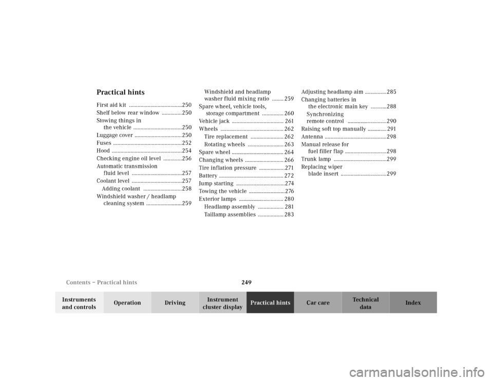
Practical hintsFirst aid kit .....................................250
Shelf below rear window ..............250
Stowing things in
the vehicle ..................................250
Luggage cover .................................250
Fuses ................................................252
Hood .................................................254
Checking engine oil level .............256
Automatic transmission
fluid level ...................................257
Coolant level ...................................257
Adding coolant ...........................258
Windshield washer / headlamp
cleaning system .........................259Windshield and headlamp
washer fluid mixing ratio ........ 259
Spare wheel, vehicle tools,
storage compartment ............... 260
Vehicle jack .................................... 261
Wheels ............................................ 262
Tire replacement ....................... 262
Rotating wheels ......................... 263
Spare wheel .................................... 264
Changing wheels ........................... 266
Tire inflation pressure ..................271
Battery ............................................. 272
Jump starting ..................................274
Towing the vehicle .........................276
Exterior lamps ............................... 280
Headlamp assembly .................. 281
Taillamp assemblies .................. 283Adjusting headlamp aim ...............285
Changing batteries in
the electronic main key ...........288
Synchronizing
remote control ...........................290
Raising soft top manually ............. 291
Antenna ...........................................298
Manual release for
fuel filler flap .............................298
Trunk lamp .....................................299
Replacing wiper
blade insert ................................299
Page 276 of 341

273 Battery
Te ch n ica l
data Instruments
and controlsOperation DrivingInstrument
cluster displayPractical hintsCar care Index Therefore, we strongly recommend that you have the
battery charge checked frequently, and corrected if
necessary, especially if you use the vehicle less than
approximately 200 miles (300 km) per month,
mostly for short distance trips, or if it is not used for
long periods of time.
Only charge a battery with a battery charger after the
battery has been disconnected from the vehicle’s
electrical circuit.
Always disconnect the battery negative lead first and
connect last.
When removing and connecting the battery, always
make sure that all electrical consumers are off and the
electronic key is in steering lock position 0. The battery
and its filler caps must always be securely installed
when the vehicle is in operation. During removal and
installation always protect the disconnected battery
positive (+) terminal with the cover attached to the
battery.
While the engine is running the battery terminal clamps
must not be loosened or detached, otherwise the
generator and other electronic components would be
damaged.Notes:
After reconnecting the battery also set the clock (see
page 106) resynchronize the front seats (see page 49),
front seat head restraints (see page 49), the express
feature of the power windows (see page 147), and the
electronic stability program (ESP) (see page 221).
If the soft top is in a half open position, it also has to be
synchronized. To do so, raise and lock soft top manually
(see page 291).
Battery recycling
Batteries contain material that can harm the
environment with improper disposal.
Large 12 Volt storage batteries contain lead.
Recycling of batteries is the preferred method of
disposal.
Many states require sellers of batteries to accept old
batteries for recycling.
Page 291 of 341

288 Electronic main key
Te ch n ica l
data Instruments
and controlsOperation DrivingInstrument
cluster displayPractical hintsCar care Index
Changing batteries in the electronic main key
1Transmit buttons
2Lamp for battery check and function control
Checking batteries
If one of the transmit buttons (1) is pressed, the battery
check lamp (2) lights up briefly – indicating that the
batteries are in order.
Change batteries if the battery check lamp (2) does not
light up briefly.Changing batteries
Move locking tab (3) in direction of right arrow and
remove mechanical key (4, left arrow).
P80.20-2201-26
1
2
P80.35-2029-26
4
3