2001 LAND ROVER FREELANDER battery location
[x] Cancel search: battery locationPage 349 of 1007

FUEL DELIVERY SYSTEM - PETROL
19-2-28 REPAIRS
Filter - main
$% 19.25.02
Remove
1.Disconnect battery earth lead.
2.Remove sender unit.
+ INSTRUMENTS, REPAIRS, Sender
unit - fuel tank gauge.
3.Disconnect 2 Lucars from top of pump unit
assembly.
4.Release 3 slots in top of pump unit assembly
from lugs in base.
5.Carefully manoeuvre top of pump unit
assembly away from base, ensuring that fuel
feed hose does not become strained.
6.Collect compression spring from fuel filter.
7.Carefully release 3 sprag clips securing fuel
filter.8.Release fuel filter from inlet and outlet
connections.
9.Remove fuel filter.
10.Collect 'O' rings.
Refit
1.Lubricate NEW 'O' rings with silicone grease
and fit to ports.
2.Carefully fit fuel filter to ports and push fully
home, ensuring that sprag clips engage fully.
WARNING: Ensure earthing spring fitted to
fuel pressure regulator is correctly located.
3.Position spring to fuel filter recess and engage
in top location.
WARNING: Ensure that filter earthing tag is
correctly located to contact the base of fuel
filter.
4.Engage pump top to base, ensuring that slots
engage correctly with lugs.
WARNING: During refit, ensure that all
electrical connections are made correctly.
Earth tag on fuel pump negative terminal
must not become distorted.
5.Fit sender unit.
+ INSTRUMENTS, REPAIRS, Sender
unit - fuel tank gauge.
6.Connect battery earth lead.
Page 474 of 1007

DRIVESHAFTS
REPAIRS 47-7
10.With assistance pull hub assembly outwards
and release drive shaft outer joint from hub
assembly.
11.Taking care not to damage 'Flinger', release
drive shaft inner joint from differential using
LRT-51-014 and remove drive shaft.
12.Remove and discard drive shaft circlip.Refit
1.Inspect differential seal, renew if worn or
damaged.
2.Clean ends of drive shaft and locations in hub
and differential.
3.Lubricate oil seal running surface with
transmission oil.
4.Fit new circlip to drive shaft.
5.Fit drive shaft to differential and push fully
home.
CAUTION: Pull the drive shaft to ensure the
circlip is fully engaged and retains the shaft.
6.With assistance fit drive shaft to hub.
7.Fit new drive shaft nut but do not tighten at this
stage.
8.Fit nut, bolt and dynamic damper to adjustable
transverse link and tighten to 120 Nm (89 lbf.ft).
CAUTION: Nuts and bolts must be tightened
with the weight of the vehicle on the
suspension.
9.Fit nut and bolt to fixed transverse link and
tighten to 120 Nm (89 lbf.ft).
10.Fit spacer, nut and bolt to trailing link and
tighten to 120 Nm (89 lbf.ft).
11.Fit new drive shaft nut and tighten to 400 Nm
(295 lbf.ft). Stake nut to shaft.
12.Check and top up oil level.
+ MAINTENANCE, MAINTENANCE,
Rear Axle.
13.Fit road wheel(s) and tighten nuts to 115 Nm 85
lbf.ft).
14.Remove stands and lower vehicle.
15.Connect battery earth lead.
Page 862 of 1007

CORROSION PREVENTION AND SEALING
LEAK DETECTION 77-4-31
LEAK DETECT ION
Water Leaks
Where water leakage is involved, always adopt a logical approach to the problem using a combination of skill,
experience and intuition. Do not reach a conclusion based only on visual evidence, such as assuming that a wet
footwell is caused by a leak emanating from the windscreen. It will often be found that the source of the leak is
elsewhere. Use of the correct procedure will increase the chance of locating a leak, however obscure it may seem.
Tools and equipment
The following tools and equipment are recommended for the purpose of detection and rectification of water leaks:
1Garden sprayer (hand-operated).
2Wet/dry vacuum cleaner.
3Dry, absorbent cloths.
4Battery torch.
5Small mirror.
6Weatherstrip locating tool.
7Trim panel remover.
8Small wooden or plastic wedges.
9Dry compressed air supply.
10Hot air blower.
11Sealer applicators.
12Ultrasonic leak detector.
During leak detection, the vehicle should be considered in three basic sections:
lThe front interior space.
lThe rear passenger space.
lThe loadspace or boot.
Testing
From the information supplied by the customer it should be possible for the bodyshop operator to locate the starting
point from which the leak may be detected. After the area of the leak has been identified, find the actual point of entry
into the vehicle.
A simple and effective means in the first instance is an ordinary garden spray with provision for pressure and jet
adjustment, which will allow water to be directed in a jet or turned into a fine spray. Use a mirror and a battery-powered
torch (NOT a mains voltage inspection lamp) to see into dark corners.
The sequence of testing is particularly important. Start at the lowest point and work slowly upwards, to avoid testing
in one area while masking the leak in another. For example, if testing started at the level of the windscreen, any water
cascading into the plenum chamber could leak through a bulkhead grommet and into the footwells. Even at this point
it could still be wrongly assumed that the windscreen seal was at fault.
Another important part of identifying a water leak is by visual examination of door aperture seals, grommets and
weatherstrips for damage, deterioration or misalignment, together with the fit of the door itself against the seals.
Sealing
When the point of the leak has been detected, it will then be necessary to rectify it using the following procedure:
1Renew all door aperture seals and weatherstrips which have suffered damage, misalignment or deterioration.
2Check all body seals to ensure that they are correctly located on their mounting flanges/faces using a lipping
tool if necessary.
3Dry out body seams to be treated using compressed air and/or a hot air blower as necessary.
4Apply sealant on the outside of the joint wherever possible to ensure the exclusion of water.
5When rectifying leaks between a screen glass and its weatherstrip (or in the case of direct glazing, between the
glass and bodywork), avoid removing the glass if possible. Apply the approved material at the appropriate
location (i.e. glass to weatherstrip or glass to body).
Page 1005 of 1007

INSTRUMENTS
88-6 REPAIRS
Sender unit - fuel tank gauge
$% 88.25.32
Remove
1.Disconnect battery earth lead.
2.Remove fuel pump assembly.
+ FUEL DELIVERY SYSTEM -
PETROL, REPAIRS, Pump - fuel.
+ FUEL DELIVERY SYSTEM - DIESEL,
REPAIRS, Pump - integral - fuel tank - rear -
up to 03MY.
WARNING: Fuel vapour is highly flammable
and in confined spaces is also explosive
and toxic. Always have a fire extinguisher
containing foam, CO
2, gas or powder close
at hand when handling or draining fuel.
3.Disconnect 2 Lucars from top of pump unit
assembly.
4.Release sprag clip securing sender to pump
unit assembly.
5.Remove sender unit.
Refit
1.Position sender to location slots and engage
sprag clip.
CAUTION: Ensure that each of the 4
location lugs on the sender are engaged
with corresponding slots in the tank unit.
2.Connect Lucars to top of pump unit assembly.
3.Fit fuel pump assembly.
+ FUEL DELIVERY SYSTEM -
PETROL, REPAIRS, Pump - fuel.
+ FUEL DELIVERY SYSTEM - DIESEL,
REPAIRS, Pump - integral - fuel tank - rear -
up to 03MY.
4.Connect battery earth lead.
Sender unit assembly - fuel tank - Td4
models - from 03MY
$% 88.25.37
Remove
1.Disconnect battery earth lead.
WARNING: Fuel vapour is highly flammable
and in confined spaces is also explosive
and toxic. Always have a fire extinguisher
containing foam, CO
2, gas or powder close
at hand when handling or draining fuel.
2.If fuel tank is full, using a fuel recovery
appliance, drain excess fuel from fuel filler neck
until a level below height of fuel pump is
obtained.
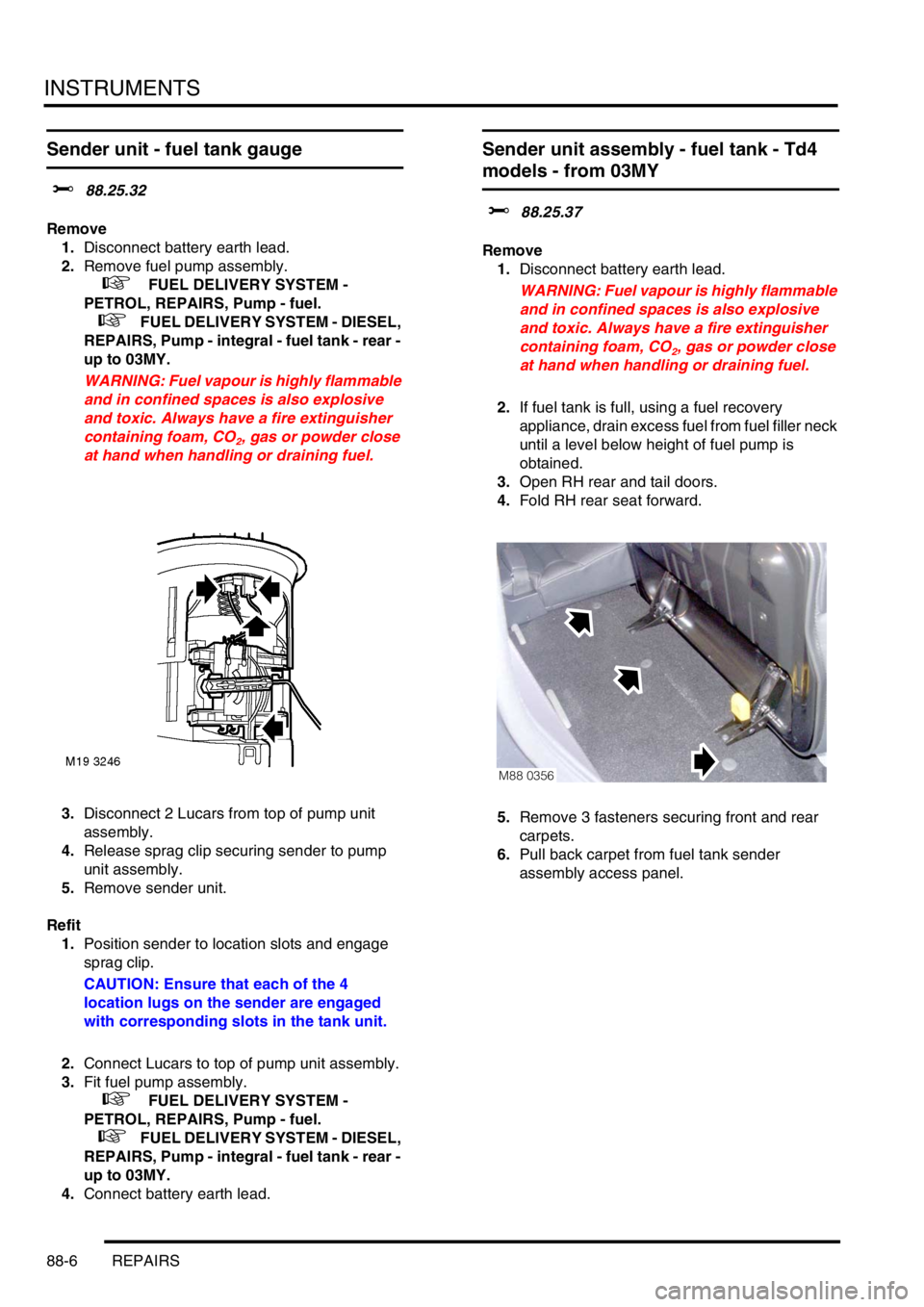
3.Open RH rear and tail doors.
4.Fold RH rear seat forward.
5.Remove 3 fasteners securing front and rear
carpets.
6.Pull back carpet from fuel tank sender
assembly access panel.
M88 0356