Page 1542 of 2395
After selecting memory, push SEND/END switch to make a
call.
NOTE:
Memory switches are not functional unless handset is
installed.
GI
MA
EM
LC
EC
FE
AT
TF
PD
AX
SU
BR
ST
RS
BT
HA
SC
IDX
INFINITI COMMUNICATOR (IVCS)
System Description (Cont'd)
EL-357
Page 1544 of 2395
Wiring Diagram Ð IVCS ÐNBEL0182
MEL868L
GI
MA
EM
LC
EC
FE
AT
TF
PD
AX
SU
BR
ST
RS
BT
HA
SC
IDX
INFINITI COMMUNICATOR (IVCS)
Wiring Diagram Ð IVCS Ð
EL-359
Page 1546 of 2395
MEL870L
GI
MA
EM
LC
EC
FE
AT
TF
PD
AX
SU
BR
ST
RS
BT
HA
SC
IDX
INFINITI COMMUNICATOR (IVCS)
Wiring Diagram Ð IVCS Ð (Cont'd)
EL-361
Page 1548 of 2395
SEL331X
CONSULT-IINBEL0183CONSULT-II INSPECTION PROCEDURENBEL0183S011. Turn ignition switch ªOFFº.
2. Insert UEN99A program card in to CONSULT-II.
3. Connect CONSULT-II to the data link connector.
SEL762W
4. Turn ignition switch ªONº.
5. Touch ªSTARTº.
SEL763W
6. Touch ªIVCSº.
SEL763W
7. Perform each diagnostic item according to the item application
chart as follows:
8. When CONSULT-II inspection is terminated, follow the proce-
dure shown below.
a. Touch ªBACKº key of CONSULT-II until ªSELECT SYSTEMº
appears, then turn off CONSULT-II.
b. Turn ignition switch to OFF position.
c. Disconnect CONSULT-II DDL connector.
NOTE:
If the DDL connector is disconnected before turning ignition
switch to ªOFFº position, INFINITI communicator may not
operate properly.
GI
MA
EM
LC
EC
FE
AT
TF
PD
AX
SU
BR
ST
RS
BT
HA
SC
IDX
INFINITI COMMUNICATOR (IVCS)
CONSULT-II
EL-363
Page 1550 of 2395

SEL442W
IIf trouble codes are displayed with ªTIME = 0º, repair/replace
the system according to ªSYMPTOM CHART 1 (SELF-DIAG-
NOSIS ITEM)º, EL-369.
IIn this case, both ªMAYDAYº and ªINFORMATIONº indicator
lamps illuminate for more than 30 seconds while the ignition
switch is in the ON position.
NOTE:
The time data in CONSULT-II ªSELF-DIAG RESULTSº mode
displays the number of ignition switch cycles without the
same malfunctioning occurring.
SEL443W
IIf trouble codes are displayed with ªTIME=1orgreaterº, it
means that the trouble code is historical data. So no further
diagnosis is required.
NOTE:
If trouble codes are displayed with ªTIME=1orgreaterº even
though the INFINITI Communicator has never been serviced.
Intermittent incidents may occur. Check the system, refer to
ªTrouble Diagnoses for Intermittent Incidentº, EL-377.
IIf the system does not detect any trouble, the IVCS indicators
will turn off after bulb check (self-diagnosis) is completed while
the ignition switch is in the ON position.
NOTE:
IThe trouble codes cannot be erased by CONSULT-II.
IAfter 50 ignition cycles, the trouble codes are no longer
displayed in the CONSULT-II ªSELF-DIAG RESULTSº
mode.
IThe IVCS unit does not count the ignition switch cycles
unless the ignition switch is OFF for more than 3 minutes
between each ignition switch cycle.
GI
MA
EM
LC
EC
FE
AT
TF
PD
AX
SU
BR
ST
RS
BT
HA
SC
IDX
INFINITI COMMUNICATOR (IVCS)
CONSULT-II (Cont'd)
EL-365
Page 1552 of 2395
SEL445W
ªREGISTERED DATAº MODENBEL0183S05
Item Description
UNIT IDID number of the IVCS unit. ID number is unique to
each unit and differs for each unit.
CELLULAR PHONE # Ð
VIN #Vehicle Identification Number. When the IVCS unit is
replaced, VIN # is written in the memory of the
replaced unit by transmitting data from the Communi-
cator Response Center.
NOTE:
No data can be changed in this CONSULT-II mode.
GI
MA
EM
LC
EC
FE
AT
TF
PD
AX
SU
BR
ST
RS
BT
HA
SC
IDX
INFINITI COMMUNICATOR (IVCS)
CONSULT-II (Cont'd)
EL-367
Page 1554 of 2395

SEL532V
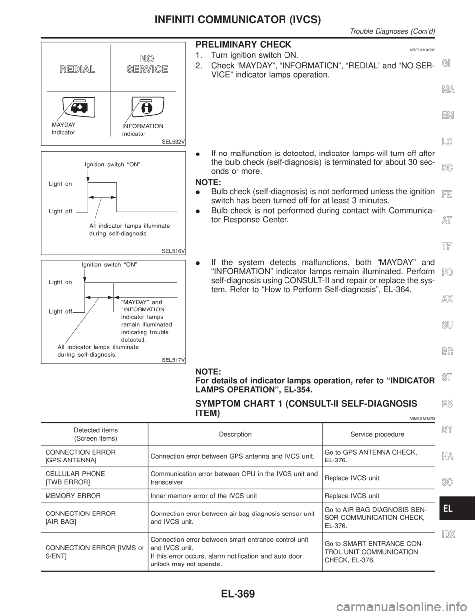
PRELIMINARY CHECKNBEL0184S021. Turn ignition switch ON.
2. Check ªMAYDAYº, ªINFORMATIONº, ªREDIALº and ªNO SER-
VICEº indicator lamps operation.
SEL516V
IIf no malfunction is detected, indicator lamps will turn off after
the bulb check (self-diagnosis) is terminated for about 30 sec-
onds or more.
NOTE:
IBulb check (self-diagnosis) is not performed unless the ignition
switch has been turned off for at least 3 minutes.
IBulb check is not performed during contact with Communica-
tor Response Center.
SEL517V
IIf the system detects malfunctions, both ªMAYDAYº and
ªINFORMATIONº indicator lamps remain illuminated. Perform
self-diagnosis using CONSULT-II and repair or replace the sys-
tem. Refer to ªHow to Perform Self-diagnosisº, EL-364.
NOTE:
For details of indicator lamps operation, refer to ªINDICATOR
LAMPS OPERATIONº, EL-354.
SYMPTOM CHART 1 (CONSULT-II SELF-DIAGNOSIS
ITEM)
NBEL0184S03
Detected items
(Screen items)Description Service procedure
CONNECTION ERROR
[GPS ANTENNA]Connection error between GPS antenna and IVCS unit.Go to GPS ANTENNA CHECK,
EL-376.
CELLULAR PHONE
[TWB ERROR]Communication error between CPU in the IVCS unit and
transceiverReplace IVCS unit.
MEMORY ERROR Inner memory error of the IVCS unit Replace IVCS unit.
CONNECTION ERROR
[AIR BAG]Connection error between air bag diagnosis sensor unit
and IVCS unit.Go to AIR BAG DIAGNOSIS SEN-
SOR COMMUNICATION CHECK,
EL-376.
CONNECTION ERROR [IVMS or
S/ENT]Connection error between smart entrance control unit
and IVCS unit.
If this error occurs, alarm notification and auto door
unlock may not operate.Go to SMART ENTRANCE CON-
TROL UNIT COMMUNICATION
CHECK, EL-376.
GI
MA
EM
LC
EC
FE
AT
TF
PD
AX
SU
BR
ST
RS
BT
HA
SC
IDX
INFINITI COMMUNICATOR (IVCS)
Trouble Diagnoses (Cont'd)
EL-369
Page 1556 of 2395
SEL976VA
POWER SUPPLY AND GROUND CIRCUIT FOR IVCS
UNIT CHECK
NBEL0184S05Main Power Supply Circuit CheckNBEL0184S0501
Terminal Ignition switch
(+) (þ) OFF ACC ON
18 GroundBattery volt-
ageBattery volt-
ageBattery volt-
age
2 Ground 0V 0VBattery volt-
age
If NG, check the following:
I15A fuse [No. 4, located in fuse and fusible link box]
I7.5A fuse [No. 11, located in fuse block (J/B)]
IHarness for open or short between fuse and IVCS unit
SEL519VB
Ground Circuit CheckNBEL0184S0502
Terminals Continuity
17 - Ground Yes
GI
MA
EM
LC
EC
FE
AT
TF
PD
AX
SU
BR
ST
RS
BT
HA
SC
IDX
INFINITI COMMUNICATOR (IVCS)
Trouble Diagnoses (Cont'd)
EL-371