Page 264 of 2395
3 CHECK PNP SWITCH CIRCUIT (Without CONSULT-II)
Without CONSULT-II
1. Turn ignition switch to ªONº position.
(Do not start engine.)
2. Check voltage between TCM terminals 26, 27, 34, 35, 36 and ground while moving selector lever through each posi-
tion.
MTBL0205
SAT517J
Does battery voltage exist (B) or non-existent (0)?
Ye s©GO TO 5.
No©GO TO 4.
4 DETECT MALFUNCTIONING ITEM
Check the following items:
IPNP switch
Refer to ªComponent Inspectionº, AT-263.
IHarness for short or open between ignition switch and PNP switch (Main harness)
IHarness for short or open between PNP switch and TCM (Main harness)
OK or NG
OK©GO TO 5.
NG©Repair or replace damaged parts.
GI
MA
EM
LC
EC
FE
TF
PD
AX
SU
BR
ST
RS
BT
HA
SC
EL
IDX
TROUBLE DIAGNOSES FOR SYMPTOMS
21. TCM Self-diagnosis Does Not Activate (PNP, Overdrive Control and Throttle Position Switches Circuit Checks) (Cont'd)
AT-259
Page 265 of 2395

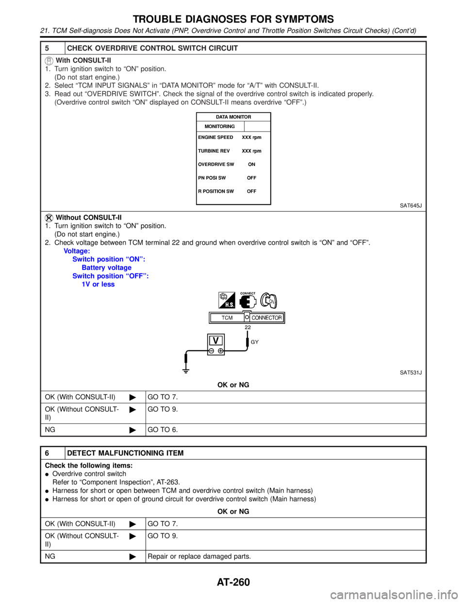
5 CHECK OVERDRIVE CONTROL SWITCH CIRCUIT
With CONSULT-II
1. Turn ignition switch to ªONº position.
(Do not start engine.)
2. Select ªTCM INPUT SIGNALSº in ªDATA MONITORº mode for ªA/Tº with CONSULT-II.
3. Read out ªOVERDRIVE SWITCHº. Check the signal of the overdrive control switch is indicated properly.
(Overdrive control switch ªONº displayed on CONSULT-II means overdrive ªOFFº.)
SAT645J
Without CONSULT-II
1. Turn ignition switch to ªONº position.
(Do not start engine.)
2. Check voltage between TCM terminal 22 and ground when overdrive control switch is ªONº and ªOFFº.
Voltage:
Switch position ªONº:
Battery voltage
Switch position ªOFFº:
1V or less
SAT531J
OK or NG
OK (With CONSULT-II)©GO TO 7.
OK (Without CONSULT-
II)©GO TO 9.
NG©GO TO 6.
6 DETECT MALFUNCTIONING ITEM
Check the following items:
IOverdrive control switch
Refer to ªComponent Inspectionº, AT-263.
IHarness for short or open between TCM and overdrive control switch (Main harness)
IHarness for short or open of ground circuit for overdrive control switch (Main harness)
OK or NG
OK (With CONSULT-II)©GO TO 7.
OK (Without CONSULT-
II)©GO TO 9.
NG©Repair or replace damaged parts.
TROUBLE DIAGNOSES FOR SYMPTOMS
21. TCM Self-diagnosis Does Not Activate (PNP, Overdrive Control and Throttle Position Switches Circuit Checks) (Cont'd)
AT-260
Page 266 of 2395

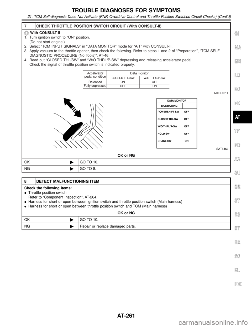
7 CHECK THROTTLE POSITION SWITCH CIRCUIT (With CONSULT-II)
With CONSULT-II
1. Turn ignition switch to ªONº position.
(Do not start engine.)
2. Select ªTCM INPUT SIGNALSº in ªDATA MONITORº mode for ªA/Tº with CONSULT-II.
3. Apply vacuum to the throttle opener, then check the following. Refer to steps 1 and 2 of ªPreparationº, ªTCM SELF-
DIAGNOSTIC PROCEDURE (No Tools)º, AT-46.
4. Read out ªCLOSED THL/SWº and ªW/O THRL/P-SWº depressing and releasing accelerator pedal.
Check the signal of throttle position switch is indicated properly.
MTBL0011
SAT646J
OK or NG
OK©GO TO 10.
NG©GO TO 8.
8 DETECT MALFUNCTIONING ITEM
Check the following items:
IThrottle position switch
Refer to ªComponent Inspectionº, AT-264.
IHarness for short or open between ignition switch and throttle position switch (Main harness)
IHarness for short or open between throttle position switch and TCM (Main harness)
OK or NG
OK©GO TO 10.
NG©Repair or replace damaged parts.
GI
MA
EM
LC
EC
FE
TF
PD
AX
SU
BR
ST
RS
BT
HA
SC
EL
IDX
TROUBLE DIAGNOSES FOR SYMPTOMS
21. TCM Self-diagnosis Does Not Activate (PNP, Overdrive Control and Throttle Position Switches Circuit Checks) (Cont'd)
AT-261
Page 267 of 2395
9 CHECK THROTTLE POSITION SWITCH CIRCUIT (Without CONSULT-II)
Without CONSULT-II
1. Turn ignition switch to ªONº position.
(Do not start engine.)
2. Check voltage between TCM terminals 16, 17 and ground while depressing, and releasing accelerator pedal slowly.
(after warming up engine)
[Refer to ªPreparationº, ªTCM SELF-DIAGNOSTIC PROCEDURE (No Tools)º, AT-46.]
MTBL0519
SAT526J
OK or NG
OK©GO TO 10.
NG©GO TO 8.
10 CHECK DTC
Perform Diagnostic procedure, AT-258.
OK or NG
OK©INSPECTION END
NG©GO TO 11.
11 CHECK TCM INSPECTION
1. Perform TCM input/output signal inspection.
2. If NG, recheck TCM pin terminals for damage or loose connection with harness connector.
OK or NG
OK©INSPECTION END
NG©Repair or replace damaged parts.
TROUBLE DIAGNOSES FOR SYMPTOMS
21. TCM Self-diagnosis Does Not Activate (PNP, Overdrive Control and Throttle Position Switches Circuit Checks) (Cont'd)
AT-262
Page 269 of 2395

SAT132K
Throttle Position SwitchNBAT0204S0403Closed Throttle Position Switch (Idle Position)
ICheck continuity between terminals 5 and 6.
[Refer to ªPreparationº, ªTCM SELF-DIAGNOSTIC PROCE-
DURE (No Tools)º, AT-46.]
Accelerator pedal condition Continuity
Released Yes
Depressed No
ITo adjust closed throttle position switch, refer to EC-431, ªSystem
Descriptionº.
SAT137K
Wide Open Throttle Position Switch
ICheck continuity between terminals 4 and 5.
Accelerator pedal condition Continuity
Released No
Depressed Yes
SAT251JA
A/T Fluid Temperature SwitchNBAT0204S04041. Make sure the A/T fluid warning lamp lights when the key is
inserted and turned to ªONº.
2. Make sure the A/T fluid warning lamp goes off when turning the
ignition switch to ªONº.
3. Check resistance between terminal 10 and ground while
changing temperature as shown at left.
Temperature ÉC (ÉF) Resistance
140 (284) or more Yes
140 (284) or less No
TROUBLE DIAGNOSES FOR SYMPTOMS
21. TCM Self-diagnosis Does Not Activate (PNP, Overdrive Control and Throttle Position Switches Circuit Checks) (Cont'd)
AT-264
Page 272 of 2395

Diagnostic ProcedureNBAT0095SYMPTOM 1:
ISelector lever cannot be moved from ªPº position with key
in ªONº position and brake pedal applied.
ISelector lever can be moved from ªPº position with key in
ªONº position and brake pedal released.
ISelector lever can be moved from ªPº position when key
is removed from key cylinder.
SYMPTOM 2:
Ignition key cannot be removed when selector lever is set to
ªPº position. It can be removed when selector lever is set to
any position except ªPº.
1 CHECK KEY INTERLOCK CABLE
Check key interlock cable for damage.
OK or NG
OK©GO TO 2.
NG©Repair key interlock cable. Refer to ªKey Interlock Cableº, AT-271.
2 CHECK SELECTOR LEVER POSITION
Check selector lever position for damage.
OK or NG
OK©GO TO 3.
NG©Check selector lever. Refer to ªON-VEHICLE SERVICE Ð PNP Switch and Manual Con-
trol Linkage Adjustmentº, AT-276 and AT-276.
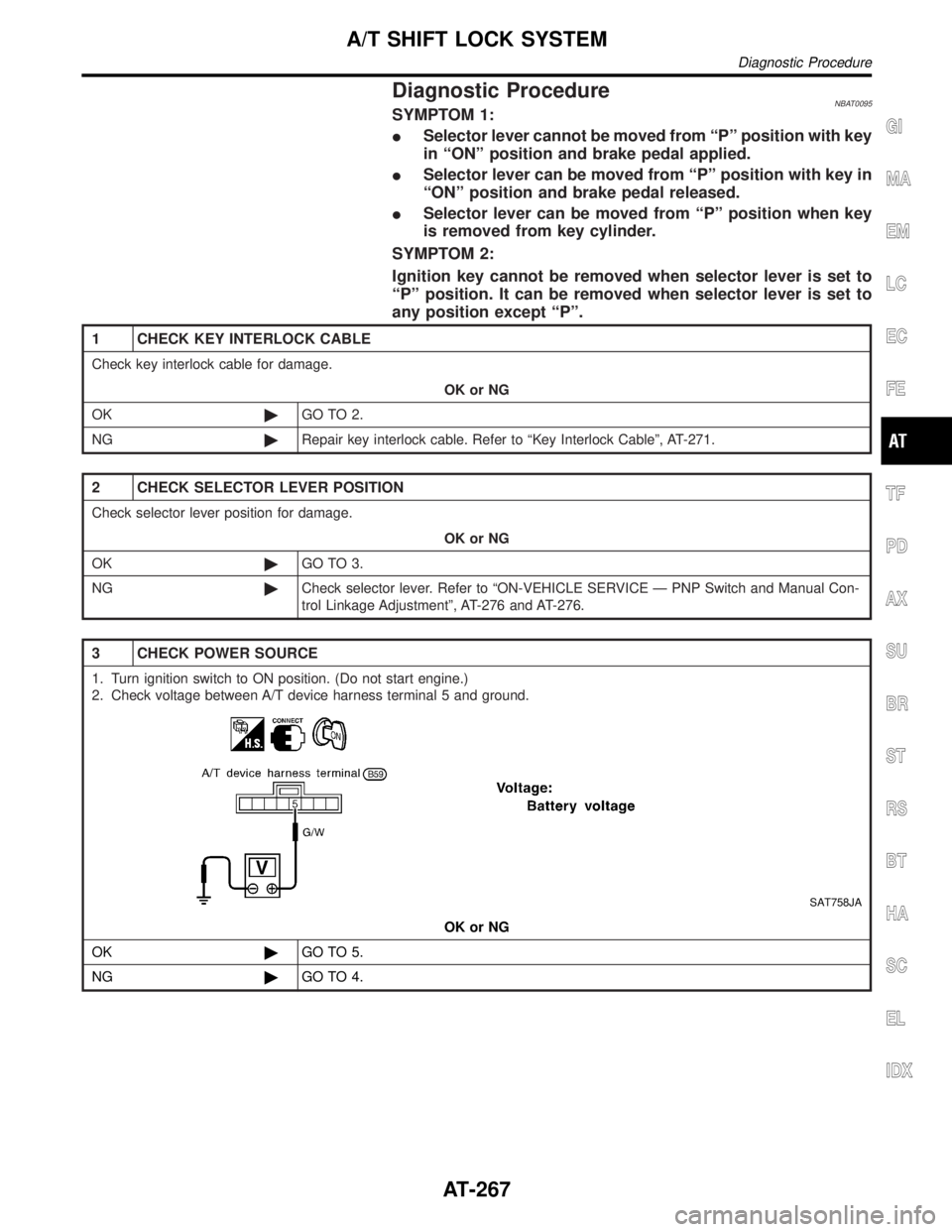
3 CHECK POWER SOURCE
1. Turn ignition switch to ON position. (Do not start engine.)
2. Check voltage between A/T device harness terminal 5 and ground.
SAT758JA
OK or NG
OK©GO TO 5.
NG©GO TO 4.
GI
MA
EM
LC
EC
FE
TF
PD
AX
SU
BR
ST
RS
BT
HA
SC
EL
IDX
A/T SHIFT LOCK SYSTEM
Diagnostic Procedure
AT-267
Page 273 of 2395
![INFINITI QX4 2001 Factory Service Manual 4 DETECT MALFUNCTIONING ITEM
Check the following items:
1. Harness for short or open between ignition switch and A/T device harness terminal 5
2. 7.5A fuse [No. 11, located in the fuse block (J/B)]
3. INFINITI QX4 2001 Factory Service Manual 4 DETECT MALFUNCTIONING ITEM
Check the following items:
1. Harness for short or open between ignition switch and A/T device harness terminal 5
2. 7.5A fuse [No. 11, located in the fuse block (J/B)]
3.](/manual-img/42/57027/w960_57027-272.png)
4 DETECT MALFUNCTIONING ITEM
Check the following items:
1. Harness for short or open between ignition switch and A/T device harness terminal 5
2. 7.5A fuse [No. 11, located in the fuse block (J/B)]
3. Ignition switch (Refer to EL-9, ªSchematicº.)
OK or NG
OK©GO TO 5.
NG©Repair or replace damaged parts.
5 CHECK INPUT SIGNAL A/T DEVICE
Turn ignition switch to OFF position.
ICheck voltage between A/T device harness terminal 7 and ground.
SAT179K
OK or NG
OK©GO TO 7.
NG©GO TO 6.
6 DETECT MALFUNCTIONING ITEM
Check the following items:
1. Harness for short or open between battery and stop lamp switch harness connector 1
2. Harness for short or open between stop lamp switch harness connector 2 and A/T device harness connector 7
3. Diode
4. 10A fuse [No. 14, located in the fuse block (J/B)]
5. Stop lamp switch
a. Check continuity between terminals 1 and 2.
SAT146K
Check stop lamp switch after adjusting brake pedal Ð refer to BR-14, ªAdjustmentº.
OK or NG
OK©GO TO 7.
NG©Repair or replace damaged parts.
A/T SHIFT LOCK SYSTEM
Diagnostic Procedure (Cont'd)
AT-268
Page 274 of 2395
7 CHECK GROUND CIRCUIT
1. Turn ignition switch to OFF position.
2. Disconnect A/T device harness connector.
3. Check continuity between A/T device harness terminal 6 and ground. Refer to wiring diagram Ð SHIFT Ð.
Continuity should exist.
If OK, check harness for short to ground and short to power.
OK or NG
OK©GO TO 8.
NG©Repair open circuit or short to ground or short to power in harness or connectors.
8 CHECK RELAY CIRCUIT
1. Turn ignition switch to ON and OFF position.
ICheck continuity between terminals 1, 2, 3 and 5.
SAT775J
YesorNo
Ye s©GO TO 9.
No©Replace relay.
9 CHECK PARK POSITION SWITCH
ICheck continuity between A/T device harness terminal 6 and relay (park position switch) harness terminal 1.
SAT180K
OK or NG
OK©GO TO 10.
NG©Replace park position switch.
GI
MA
EM
LC
EC
FE
TF
PD
AX
SU
BR
ST
RS
BT
HA
SC
EL
IDX
A/T SHIFT LOCK SYSTEM
Diagnostic Procedure (Cont'd)
AT-269