2001 INFINITI QX4 Crankshaft position sensor pos
[x] Cancel search: Crankshaft position sensor posPage 1667 of 2395

SEM421G
SEM422G
13. Remove camshaft position sensor (PHASE), CVTC sensors
and crankshaft position sensor (REF).
IAvoid impact such as dropping.
IDo not disassemble the components.
IDo not place them on areas where iron powder may adhere.
IKeep away from the objects susceptible to magnetism.
SEM412G
14. Remove upper intake manifold collector in reverse order of
installation. Refer to EM-12, ªUpper Intake Manifold Collectorº.
SEM413G
15. Remove intake manifold collector support bolts.
SEM414G
16. Remove lower intake manifold collector in reverse order of
installation. Refer to EM-13, ªLower Intake Manifold Collectorº.
TIMING CHAIN
Removal (Cont'd)
EM-24
Page 1676 of 2395

SEM439G
SEM440G
17. Install RH and LH rocker covers.
Rocker cover tightening procedure:
ITighten in numerical order as shown in the figure.
a. Tighten bolts 1 to 10 in that order to 6.9 to 8.8 N´m (0.7 to 0.9
kg-m, 61 to 78 in-lb).
b. Then tighten bolts 1 to 10 as indicated in figure to 6.9 to 8.8
N´m (0.7 to 0.9 kg-m, 61 to 78 in-lb).
18. Hang engine using the right and left side engine slingers with
a suitable hoist.
19. Set a suitable transmission jack under the suspension mem-
ber.
20. Remove right and left side engine mounting nuts.
21. Remove right and left side suspension member bolts.
22. Install aluminum oil pan. Refer to EM-18, ªInstallationº.
23. Set ring gear stopper using the mounting bolt hole.
IBe careful not to damage the signal plate teeth.
SEM417G
24. Install crankshaft pulley to crankshaft.
IAlign pointer with TDC mark on crankshaft pulley.
SEM531G
25. Install crankshaft pulley bolt.
ILubricate thread and seat surface of the bolt with new
engine oil.
a. Tighten to 39 to 49 N´m (4.0 to 5.0 kg-m, 29 to 36 ft-lb).
b. Put a paint mark on the crankshaft pulley.
SEM963E
c. Again tighten by turning 60É to 66É, about the angle from one
hexagon bolt head corner to another.
26. Install camshaft position sensor (PHASE), crankshaft position
sensors (REF)/(POS) and CVTC sensors.
27. Reinstall removed parts in the reverse order of removal.
IWhen installing fuel tube and intake manifold collectors, refer
to EM-12, ªTIGHTENING PROCEDURESº.
IAfter starting engine, keep idling for three minutes. Then
rev engine up to 3,000 rpm under no load to purge air from
the high-pressure chamber of the chain tensioners. The
engine may produce a rattling noise. This indicates that
GI
MA
LC
EC
FE
AT
TF
PD
AX
SU
BR
ST
RS
BT
HA
SC
EL
IDX
TIMING CHAIN
Installation (Cont'd)
EM-33
Page 1678 of 2395
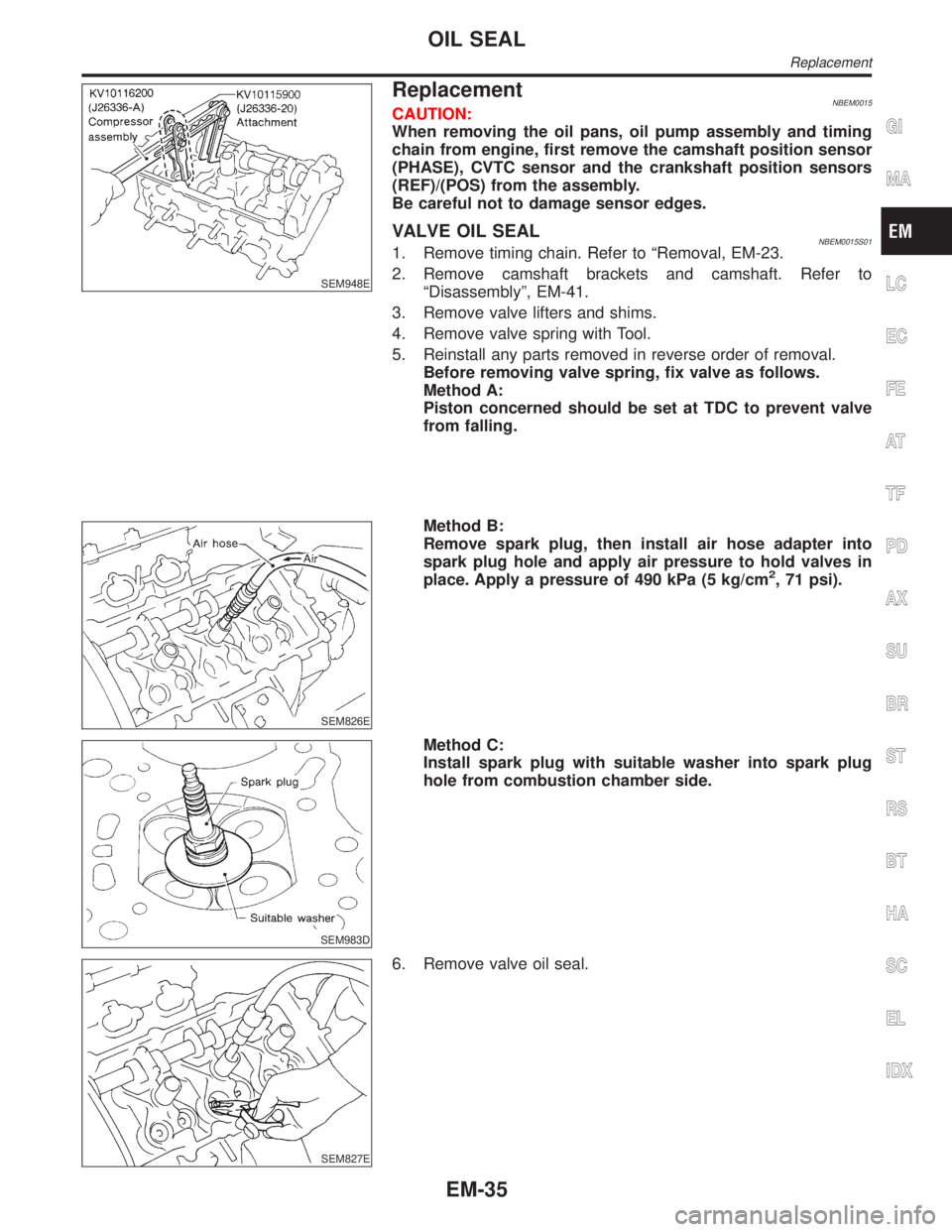
SEM948E
ReplacementNBEM0015CAUTION:
When removing the oil pans, oil pump assembly and timing
chain from engine, first remove the camshaft position sensor
(PHASE), CVTC sensor and the crankshaft position sensors
(REF)/(POS) from the assembly.
Be careful not to damage sensor edges.
VALVE OIL SEALNBEM0015S011. Remove timing chain. Refer to ªRemoval, EM-23.
2. Remove camshaft brackets and camshaft. Refer to
ªDisassemblyº, EM-41.
3. Remove valve lifters and shims.
4. Remove valve spring with Tool.
5. Reinstall any parts removed in reverse order of removal.
Before removing valve spring, fix valve as follows.
Method A:
Piston concerned should be set at TDC to prevent valve
from falling.
SEM826E
Method B:
Remove spark plug, then install air hose adapter into
spark plug hole and apply air pressure to hold valves in
place. Apply a pressure of 490 kPa (5 kg/cm
2, 71 psi).
SEM983D
Method C:
Install spark plug with suitable washer into spark plug
hole from combustion chamber side.
SEM827E
6. Remove valve oil seal.
GI
MA
LC
EC
FE
AT
TF
PD
AX
SU
BR
ST
RS
BT
HA
SC
EL
IDX
OIL SEAL
Replacement
EM-35
Page 1679 of 2395
SEM828E
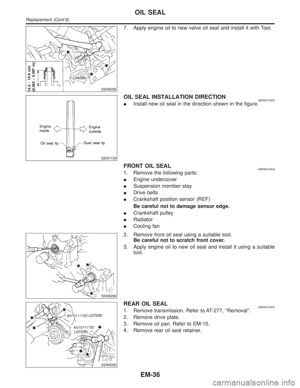
7. Apply engine oil to new valve oil seal and install it with Tool.
SEM715A
OIL SEAL INSTALLATION DIRECTIONNBEM0015S02IInstall new oil seal in the direction shown in the figure.
FRONT OIL SEALNBEM0015S031. Remove the following parts:
IEngine undercover
ISuspension member stay
IDrive belts
ICrankshaft position sensor (REF)
Be careful not to damage sensor edge.
ICrankshaft pulley
IRadiator
ICooling fan
SEM829E
2. Remove front oil seal using a suitable tool.
Be careful not to scratch front cover.
3. Apply engine oil to new oil seal and install it using a suitable
tool.
SEM830E
REAR OIL SEALNBEM0015S041. Remove transmission. Refer to AT-277, ªRemovalº.
2. Remove drive plate.
3. Remove oil pan. Refer to EM-15.
4. Remove rear oil seal retainer.
OIL SEAL
Replacement (Cont'd)
EM-36
Page 1700 of 2395
Removal and InstallationNBEM0042WARNING:
ISituate vehicle on a flat and solid surface.
IPlace chocks at front and back of rear wheels.
IDo not remove engine until exhaust system has com-
pletely cooled off. Otherwise, you may burn yourself
and/or fire may break out in fuel line.
IFor safety during subsequent steps, the tension of wires
should be slackened against the engine.
IBefore disconnecting fuel hose, release fuel pressure
from fuel line.
Refer to EC-39, ªFuel Pressure Releaseº.
IBefore removing front axle from transmission, place
safety stands under designated front supporting points.
Refer to GI section for lifting points and towing.
IBe sure to hoist engine and transmission in a safe man-
ner.
IFor engines not equipped with engine slingers, attach
proper slingers and bolts described in PARTS CATALOG.
CAUTION:
IWhen lifting engine, be careful not to strike adjacent parts,
especially accelerator wire casing, brake lines, and brake
master cylinder.
IIn hoisting the engine, always use engine slingers in a
safe manner.
IBefore separating engine and transmission, remove
crankshaft position sensor (POS) from the assembly.
IAlways take extra care not to damage edge of crankshaft
position sensor (POS), or ring gear teeth.GI
MA
LC
EC
FE
AT
TF
PD
AX
SU
BR
ST
RS
BT
HA
SC
EL
IDX
ENGINE ASSEMBLY
Removal and Installation
EM-57
Page 1796 of 2395
NBGI0010
SAE J1930 Terminology ListNBGI0010S01All emission related terms used in this publication in accordance with SAE J1930 are listed. Accordingly, new
terms, new acronyms/abbreviations and old terms are listed in the following chart.
NEW TERMNEW ACRONYM /
ABBREVIATIONOLD TERM
Air cleaner ACL Air cleaner
Barometric pressure BARO ***
Barometric pressure sensor-BCDD BAROS-BCDD BCDD
Camshaft position CMP ***
Camshaft position sensor CMPS Crank angle sensor
Canister *** Canister
Carburetor CARB Carburetor
Charge air cooler CAC Intercooler
Closed loop CL Closed loop
Closed throttle position switch CTP switch Idle switch
Clutch pedal position switch CPP switch Clutch switch
Continuous fuel injection system CFI system ***
Continuous trap oxidizer system CTOX system ***
Crankshaft position CKP ***
Crankshaft position sensor CKPS ***
Data link connector DLC ***
Diagnostic test mode DTM Diagnostic mode
Diagnostic test mode selector DTM selector Diagnostic mode selector
Diagnostic test mode I DTM I Mode I
Diagnostic test mode II DTM II Mode II
Diagnostic trouble code DTC Malfunction code
Direct fuel injection system DFI system ***
Distributor ignition system DI system Ignition timing control
Early fuel evaporation-mixture heater EFE-mixture heater Mixture heater
Early fuel evaporation system EFE system Mixture heater control
Electrically erasable programmable read
only memoryEEPROM ***
Electronic ignition system EI system Ignition timing control
Engine control EC ***
Engine control module ECM ECCS control unit
Engine coolant temperature ECT Engine temperature
Engine coolant temperature sensor ECTS Engine temperature sensor
Engine modification EM ***
Engine speed RPM Engine speed
Erasable programmable read only
memoryEPROM ***MA
EM
LC
EC
FE
AT
TF
PD
AX
SU
BR
ST
RS
BT
HA
SC
EL
IDX
SAE J1930 TERMINOLOGY LIST
SAE J1930 Terminology List
GI-51
Page 1962 of 2395
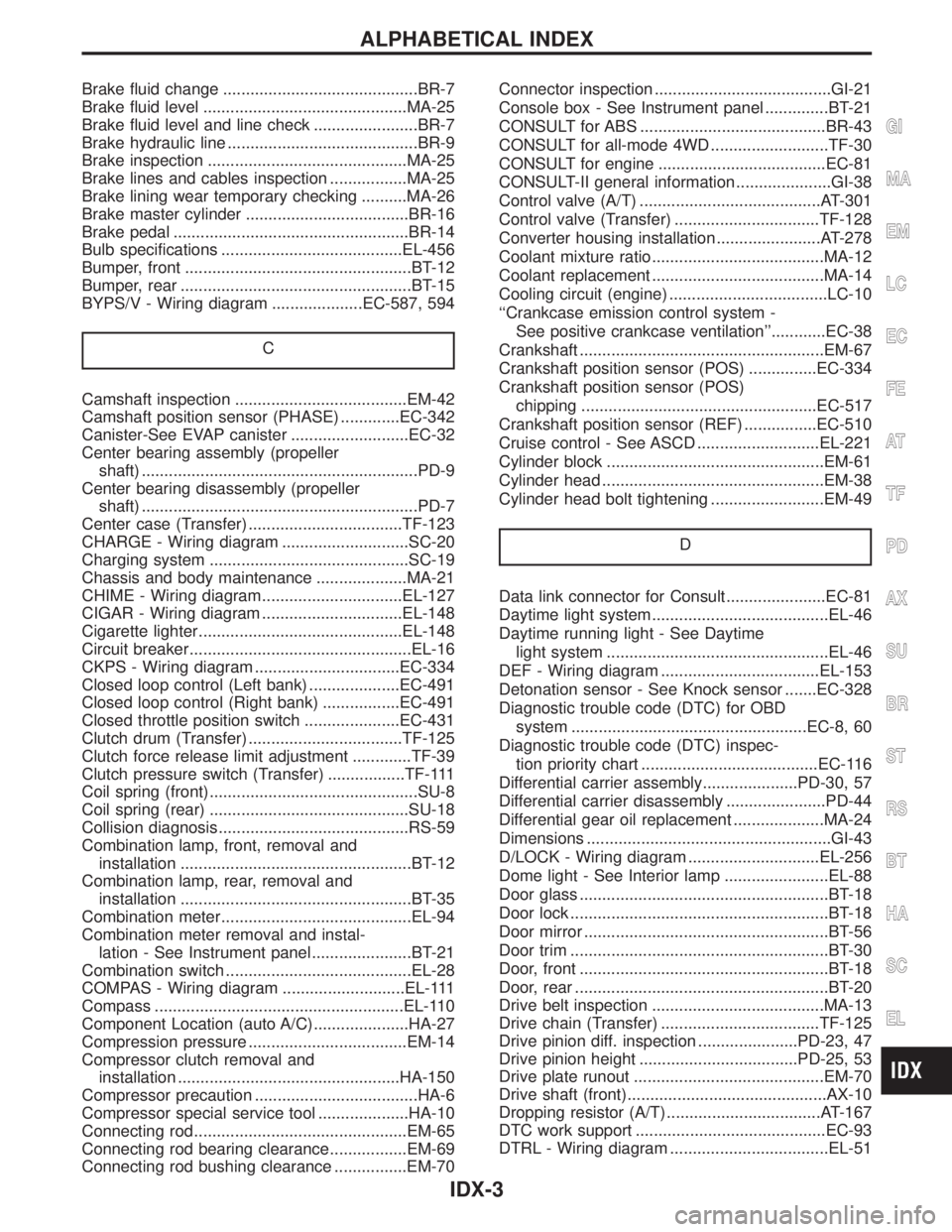
Brake fluid change ...........................................BR-7
Brake fluid level .............................................MA-25
Brake fluid level and line check .......................BR-7
Brake hydraulic line ..........................................BR-9
Brake inspection ............................................MA-25
Brake lines and cables inspection .................MA-25
Brake lining wear temporary checking ..........MA-26
Brake master cylinder ....................................BR-16
Brake pedal ....................................................BR-14
Bulb specifications ........................................EL-456
Bumper, front ..................................................BT-12
Bumper, rear ...................................................BT-15
BYPS/V - Wiring diagram ....................EC-587, 594
C
Camshaft inspection ......................................EM-42
Camshaft position sensor (PHASE) .............EC-342
Canister-See EVAP canister ..........................EC-32
Center bearing assembly (propeller
shaft) .............................................................PD-9
Center bearing disassembly (propeller
shaft) .............................................................PD-7
Center case (Transfer) ..................................TF-123
CHARGE - Wiring diagram ............................SC-20
Charging system ............................................SC-19
Chassis and body maintenance ....................MA-21
CHIME - Wiring diagram...............................EL-127
CIGAR - Wiring diagram ...............................EL-148
Cigarette lighter.............................................EL-148
Circuit breaker.................................................EL-16
CKPS - Wiring diagram ................................EC-334
Closed loop control (Left bank) ....................EC-491
Closed loop control (Right bank) .................EC-491
Closed throttle position switch .....................EC-431
Clutch drum (Transfer) ..................................TF-125
Clutch force release limit adjustment .............TF-39
Clutch pressure switch (Transfer) .................TF-111
Coil spring (front)..............................................SU-8
Coil spring (rear) ............................................SU-18
Collision diagnosis..........................................RS-59
Combination lamp, front, removal and
installation ...................................................BT-12
Combination lamp, rear, removal and
installation ...................................................BT-35
Combination meter..........................................EL-94
Combination meter removal and instal-
lation - See Instrument panel ......................BT-21
Combination switch .........................................EL-28
COMPAS - Wiring diagram ...........................EL-111
Compass .......................................................EL-110
Component Location (auto A/C).....................HA-27
Compression pressure ...................................EM-14
Compressor clutch removal and
installation .................................................HA-150
Compressor precaution ....................................HA-6
Compressor special service tool ....................HA-10
Connecting rod...............................................EM-65
Connecting rod bearing clearance.................EM-69
Connecting rod bushing clearance ................EM-70Connector inspection .......................................GI-21
Console box - See Instrument panel ..............BT-21
CONSULT for ABS .........................................BR-43
CONSULT for all-mode 4WD ..........................TF-30
CONSULT for engine .....................................EC-81
CONSULT-II general information .....................GI-38
Control valve (A/T) ........................................AT-301
Control valve (Transfer) ................................TF-128
Converter housing installation .......................AT-278
Coolant mixture ratio......................................MA-12
Coolant replacement ......................................MA-14
Cooling circuit (engine) ...................................LC-10
``Crankcase emission control system -
See positive crankcase ventilation''............EC-38
Crankshaft ......................................................EM-67
Crankshaft position sensor (POS) ...............EC-334
Crankshaft position sensor (POS)
chipping ....................................................EC-517
Crankshaft position sensor (REF) ................EC-510
Cruise control - See ASCD ...........................EL-221
Cylinder block ................................................EM-61
Cylinder head .................................................EM-38
Cylinder head bolt tightening .........................EM-49
D
Data link connector for Consult......................EC-81
Daytime light system.......................................EL-46
Daytime running light - See Daytime
light system .................................................EL-46
DEF - Wiring diagram ...................................EL-153
Detonation sensor - See Knock sensor .......EC-328
Diagnostic trouble code (DTC) for OBD
system ....................................................EC-8, 60
Diagnostic trouble code (DTC) inspec-
tion priority chart .......................................EC-116
Differential carrier assembly.....................PD-30, 57
Differential carrier disassembly ......................PD-44
Differential gear oil replacement ....................MA-24
Dimensions ......................................................GI-43
D/LOCK - Wiring diagram .............................EL-256
Dome light - See Interior lamp .......................EL-88
Door glass .......................................................BT-18
Door lock .........................................................BT-18
Door mirror ......................................................BT-56
Door trim .........................................................BT-30
Door, front .......................................................BT-18
Door, rear ........................................................BT-20
Drive belt inspection ......................................MA-13
Drive chain (Transfer) ...................................TF-125
Drive pinion diff. inspection ......................PD-23, 47
Drive pinion height ...................................PD-25, 53
Drive plate runout ..........................................EM-70
Drive shaft (front)............................................AX-10
Dropping resistor (A/T) ..................................AT-167
DTC work support ..........................................EC-93
DTRL - Wiring diagram ...................................EL-51
GI
MA
EM
LC
EC
FE
AT
TF
PD
AX
SU
BR
ST
RS
BT
HA
SC
EL
ALPHABETICAL INDEX
IDX-3