2001 INFINITI QX4 engine
[x] Cancel search: enginePage 1915 of 2395
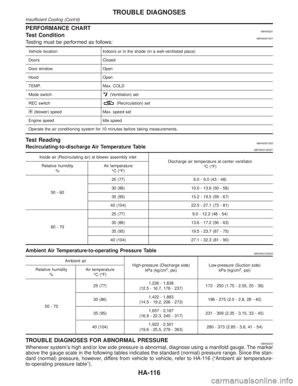
PERFORMANCE CHARTNBHA0031Test ConditionNBHA0031S01Testing must be performed as follows:
Vehicle location Indoors or in the shade (in a well-ventilated place)
Doors Closed
Door window Open
Hood Open
TEMP. Max. COLD
Mode switch
(Ventilation) set
REC switch
(Recirculation) set
(blower) speed Max. speed set
Engine speed Idle speed
Operate the air conditioning system for 10 minutes before taking measurements.
Test ReadingNBHA0031S02Recirculating-to-discharge Air Temperature TableNBHA0031S0201
Inside air (Recirculating air) at blower assembly inlet
Discharge air temperature at center ventilator
ÉC (ÉF) Relative humidity
%Air temperature
ÉC (ÉF)
50-6025 (77) 6.0 - 9.0 (43 - 48)
30 (86) 10.0 - 13.6 (50 - 56)
35 (95) 15.2 - 19.5 (59 - 67)
40 (104) 22.5 - 27.1 (73 - 81)
60-7025 (77) 9.0 - 12.2 (48 - 54)
30 (86) 13.6 - 17.2 (56 - 63)
35 (95) 19.5 - 23.7 (67 - 75)
40 (104) 27.1 - 32.3 (81 - 90)
Ambient Air Temperature-to-operating Pressure TableNBHA0031S0202
Ambient air
High-pressure (Discharge side)
kPa (kg/cm
2, psi)Low-pressure (Suction side)
kPa (kg/cm2, psi) Relative humidity
%Air temperature
ÉC (ÉF)
50-7025 (77)1,226 - 1,638
(12.5 - 16.7, 178 - 237)172 - 250 (1.75 - 2.55, 25 - 36)
30 (86)1,422 - 1,883
(14.5 - 19.2, 206 - 273)196 - 275 (2.0 - 2.8, 28 - 40)
35 (95)1,657 - 2,187
(16.9 - 22.3, 240 - 317)231 - 309 (2.35 - 3.15, 33 - 45)
40 (104)1,922 - 2,501
(19.6 - 25.5, 279 - 363)280 - 373 (2.85 - 3.8, 41 - 54)
TROUBLE DIAGNOSES FOR ABNORMAL PRESSURENBHA0032Whenever system's high and/or low side pressure is abnormal, diagnose using a manifold gauge. The marker
above the gauge scale in the following tables indicates the standard (normal) pressure range. Since the stan-
dard (normal) pressure, however, differs from vehicle to vehicle, refer to HA-116 (ªAmbient air temperature-
to-operating pressure tableº).
TROUBLE DIAGNOSES
Insufficient Cooling (Cont'd)
HA-116
Page 1916 of 2395
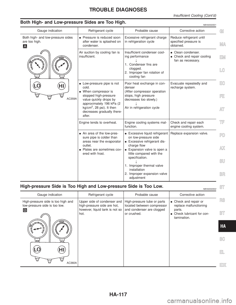
Both High- and Low-pressure Sides are Too High.NBHA0032S01
Gauge indication Refrigerant cycle Probable cause Corrective action
Both high- and low-pressure sides
are too high.
AC359A
IPressure is reduced soon
after water is splashed on
condenser.Excessive refrigerant charge
in refrigeration cycleReduce refrigerant until
specified pressure is
obtained.
Air suction by cooling fan is
insufficient.Insufficient condenser cool-
ing performance
"
1. Condenser fins are
clogged.
2. Improper fan rotation of
cooling fanIClean condenser.
ICheck and repair cooling
fan as necessary.
ILow-pressure pipe is not
cold.
IWhen compressor is
stopped high-pressure
value quickly drops by
approximately 196 kPa (2
kg/cm
2, 28 psi). It then
decreases gradually there-
after.Poor heat exchange in con-
denser
(After compressor operation
stops, high pressure
decreases too slowly.)
"
Air in refrigeration cycleEvacuate repeatedly and
recharge system.
Engine tends to overheat. Engine cooling systems mal-
function.Check and repair each
engine cooling system.
IAn area of the low-pres-
sure pipe is colder than
areas near the evaporator
outlet.
IPlates are sometimes cov-
ered with frost.IExcessive liquid refrigerant
on low-pressure side
IExcessive refrigerant dis-
charge flow
IExpansion valve is open a
little compared with the
specification.
"
1. Improper thermal valve
installation
2. Improper expansion valve
adjustmentReplace expansion valve.
High-pressure Side is Too High and Low-pressure Side is Too Low.NBHA0032S02
Gauge indication Refrigerant cycle Probable cause Corrective action
High-pressure side is too high and
low-pressure side is too low.
AC360A
Upper side of condenser and
high-pressure side are hot,
however, liquid tank is not so
hot.High-pressure tube or parts
located between compressor
and condenser are clogged
or crushed.ICheck and repair or
replace malfunctioning
parts.
ICheck lubricant for con-
tamination.
GI
MA
EM
LC
EC
FE
AT
TF
PD
AX
SU
BR
ST
RS
BT
SC
EL
IDX
TROUBLE DIAGNOSES
Insufficient Cooling (Cont'd)
HA-117
Page 1928 of 2395

With Navigation SystemNBHA0103S0102
RHA887H
*1: HA-72 *2: HA-66 *3: HA-45
RHA050G
Ambient Sensor Circuit
COMPONENT DESCRIPTIONNBHA0039The ambient sensor is attached in front of the driver's side con-
denser. It detects ambient temperature and converts it into a resis-
tance value which is then input into the auto amplifier.
AMBIENT TEMPERATURE INPUT PROCESSNBHA0040The automatic amplifier includes a ªprocessing circuitº for the ambi-
ent sensor input. However, when the temperature detected by the
ambient sensor increases quickly, the processing circuit retards the
auto amp. function. It only allows the auto amp. to recognize an
ambient temperature increase of 0.33ÉC (0.6ÉF) per 100 seconds.
As an example, consider stopping for a cup of coffee after high
speed driving. Although the actual ambient temperature has not
changed, the temperature detected by the ambient sensor will
increase. This is because the heat from the engine compartment
can radiate to the front grille area, location of the ambient sensor.
GI
MA
EM
LC
EC
FE
AT
TF
PD
AX
SU
BR
ST
RS
BT
SC
EL
IDX
TROUBLE DIAGNOSES
ECON (ECONOMY) Mode (Cont'd)
HA-129
Page 1945 of 2395
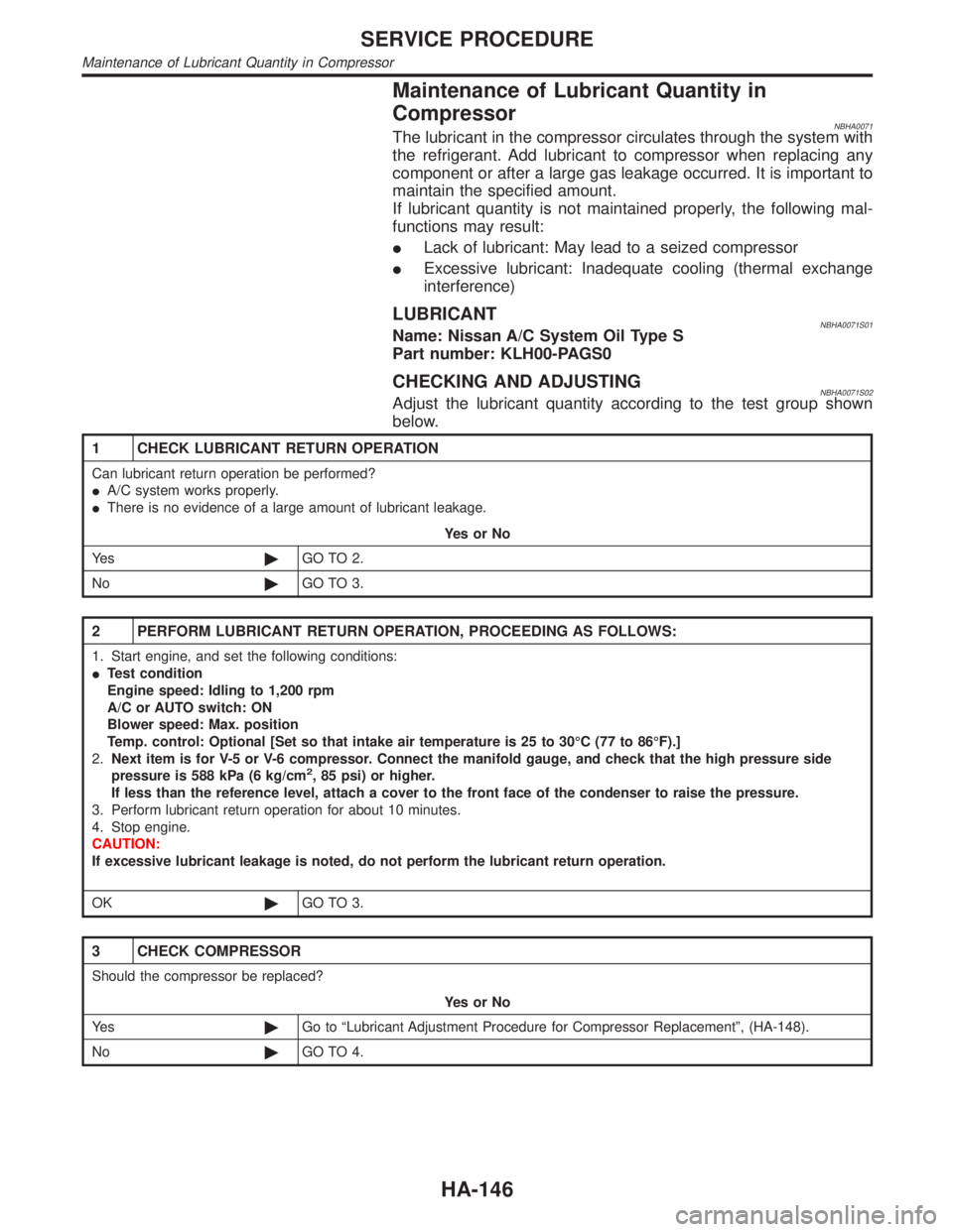
Maintenance of Lubricant Quantity in
Compressor
NBHA0071The lubricant in the compressor circulates through the system with
the refrigerant. Add lubricant to compressor when replacing any
component or after a large gas leakage occurred. It is important to
maintain the specified amount.
If lubricant quantity is not maintained properly, the following mal-
functions may result:
ILack of lubricant: May lead to a seized compressor
IExcessive lubricant: Inadequate cooling (thermal exchange
interference)
LUBRICANTNBHA0071S01Name: Nissan A/C System Oil Type S
Part number: KLH00-PAGS0
CHECKING AND ADJUSTINGNBHA0071S02Adjust the lubricant quantity according to the test group shown
below.
1 CHECK LUBRICANT RETURN OPERATION
Can lubricant return operation be performed?
IA/C system works properly.
IThere is no evidence of a large amount of lubricant leakage.
YesorNo
Ye s©GO TO 2.
No©GO TO 3.
2 PERFORM LUBRICANT RETURN OPERATION, PROCEEDING AS FOLLOWS:
1. Start engine, and set the following conditions:
ITest condition
Engine speed: Idling to 1,200 rpm
A/C or AUTO switch: ON
Blower speed: Max. position
Temp. control: Optional [Set so that intake air temperature is 25 to 30ÉC (77 to 86ÉF).]
2.Next item is for V-5 or V-6 compressor. Connect the manifold gauge, and check that the high pressure side
pressure is 588 kPa (6 kg/cm
2, 85 psi) or higher.
If less than the reference level, attach a cover to the front face of the condenser to raise the pressure.
3. Perform lubricant return operation for about 10 minutes.
4. Stop engine.
CAUTION:
If excessive lubricant leakage is noted, do not perform the lubricant return operation.
OK©GO TO 3.
3 CHECK COMPRESSOR
Should the compressor be replaced?
YesorNo
Ye s©Go to ªLubricant Adjustment Procedure for Compressor Replacementº, (HA-148).
No©GO TO 4.
SERVICE PROCEDURE
Maintenance of Lubricant Quantity in Compressor
HA-146
Page 1954 of 2395
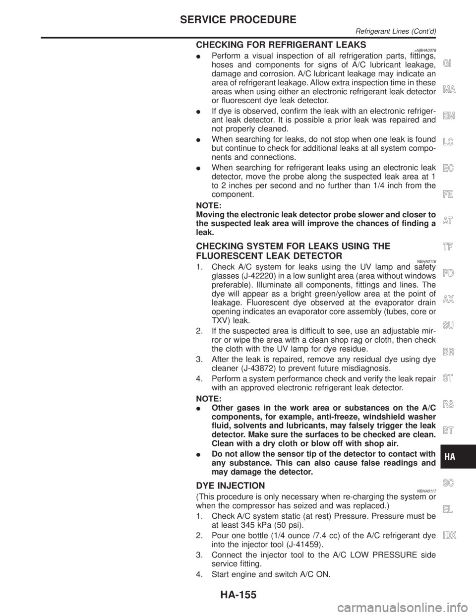
CHECKING FOR REFRIGERANT LEAKS=NBHA0078IPerform a visual inspection of all refrigeration parts, fittings,
hoses and components for signs of A/C lubricant leakage,
damage and corrosion. A/C lubricant leakage may indicate an
area of refrigerant leakage. Allow extra inspection time in these
areas when using either an electronic refrigerant leak detector
or fluorescent dye leak detector.
IIf dye is observed, confirm the leak with an electronic refriger-
ant leak detector. It is possible a prior leak was repaired and
not properly cleaned.
IWhen searching for leaks, do not stop when one leak is found
but continue to check for additional leaks at all system compo-
nents and connections.
IWhen searching for refrigerant leaks using an electronic leak
detector, move the probe along the suspected leak area at 1
to 2 inches per second and no further than 1/4 inch from the
component.
NOTE:
Moving the electronic leak detector probe slower and closer to
the suspected leak area will improve the chances of finding a
leak.
CHECKING SYSTEM FOR LEAKS USING THE
FLUORESCENT LEAK DETECTOR
NBHA01161. Check A/C system for leaks using the UV lamp and safety
glasses (J-42220) in a low sunlight area (area without windows
preferable). Illuminate all components, fittings and lines. The
dye will appear as a bright green/yellow area at the point of
leakage. Fluorescent dye observed at the evaporator drain
opening indicates an evaporator core assembly (tubes, core or
TXV) leak.
2. If the suspected area is difficult to see, use an adjustable mir-
ror or wipe the area with a clean shop rag or cloth, then check
the cloth with the UV lamp for dye residue.
3. After the leak is repaired, remove any residual dye using dye
cleaner (J-43872) to prevent future misdiagnosis.
4. Perform a system performance check and verify the leak repair
with an approved electronic refrigerant leak detector.
NOTE:
IOther gases in the work area or substances on the A/C
components, for example, anti-freeze, windshield washer
fluid, solvents and lubricants, may falsely trigger the leak
detector. Make sure the surfaces to be checked are clean.
Clean with a dry cloth or blow off with shop air.
IDo not allow the sensor tip of the detector to contact with
any substance. This can also cause false readings and
may damage the detector.
DYE INJECTIONNBHA0117(This procedure is only necessary when re-charging the system or
when the compressor has seized and was replaced.)
1. Check A/C system static (at rest) Pressure. Pressure must be
at least 345 kPa (50 psi).
2. Pour one bottle (1/4 ounce /7.4 cc) of the A/C refrigerant dye
into the injector tool (J-41459).
3. Connect the injector tool to the A/C LOW PRESSURE side
service fitting.
4. Start engine and switch A/C ON.
GI
MA
EM
LC
EC
FE
AT
TF
PD
AX
SU
BR
ST
RS
BT
SC
EL
IDX
SERVICE PROCEDURE
Refrigerant Lines (Cont'd)
HA-155
Page 1955 of 2395
5. When the A/C operating (compressor running), inject one
bottle (1/4 ounce /7.4 cc) of fluorescent dye through the low-
pressure service valve using dye injector tool J-41459 (refer to
the manufacture's operating instructions).
6. With the engine still running, disconnect the injector tool from
the service fitting.
CAUTION:
Be careful not to allow dye to spray or drip when disconnect-
ing the injector from the system.
NOTE:
If repairing the A/C system or replacing a component, pour the
dye directly into the open system connection and proceed
with the service procedures.
7. Operate the A/C system for a minimum of 20 minutes to mix
the dye with the system oil. Depending on the leak size, oper-
ating conditions and location of the leak, it may take from min-
utes to days for the dye to penetrate a leak and become visible.
SHA196FA
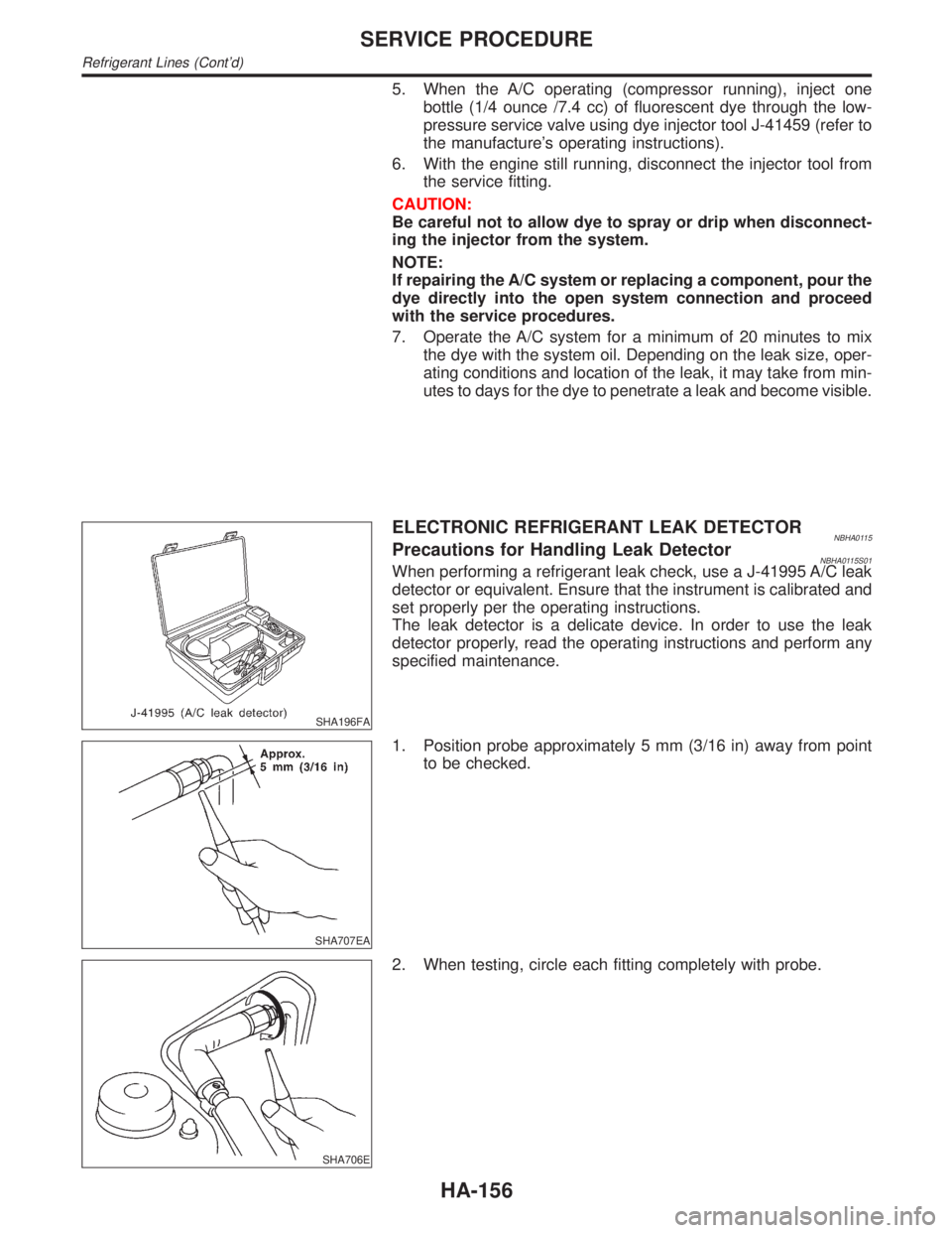
ELECTRONIC REFRIGERANT LEAK DETECTORNBHA0115Precautions for Handling Leak DetectorNBHA0115S01When performing a refrigerant leak check, use a J-41995 A/C leak
detector or equivalent. Ensure that the instrument is calibrated and
set properly per the operating instructions.
The leak detector is a delicate device. In order to use the leak
detector properly, read the operating instructions and perform any
specified maintenance.
SHA707EA
1. Position probe approximately 5 mm (3/16 in) away from point
to be checked.
SHA706E
2. When testing, circle each fitting completely with probe.
SERVICE PROCEDURE
Refrigerant Lines (Cont'd)
HA-156
Page 1956 of 2395
SHA708EA
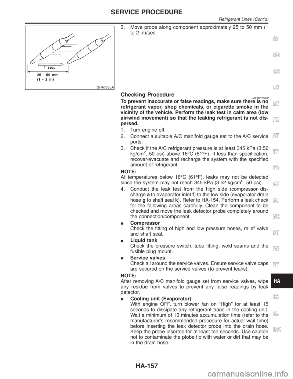
3. Move probe along component approximately 25 to 50 mm (1
to 2 in)/sec.
Checking ProcedureNBHA0115S02To prevent inaccurate or false readings, make sure there is no
refrigerant vapor, shop chemicals, or cigarette smoke in the
vicinity of the vehicle. Perform the leak test in calm area (low
air/wind movement) so that the leaking refrigerant is not dis-
persed.
1. Turn engine off.
2. Connect a suitable A/C manifold gauge set to the A/C service
ports.
3. Check if the A/C refrigerant pressure is at least 345 kPa (3.52
kg/cm
2, 50 psi) above 16ÉC (61ÉF). If less than specification,
recover/evacuate and recharge the system with the specified
amount of refrigerant.
NOTE:
At temperatures below 16ÉC (61ÉF), leaks may not be detected
since the system may not reach 345 kPa (3.52 kg/cm
2, 50 psi).
4. Conduct the leak test from the high side (compressor dis-
chargeato evaporator inletf) to the low side (evaporator drain
hosegto shaft sealk). Refer to HA-154. Perform a leak check
for the following areas carefully. Clean the component to be
checked and move the leak detector probe completely around
the connection/component.
ICompressor
Check the fitting of high and low pressure hoses, relief valve
and shaft seal.
ILiquid tank
Check the pressure switch, tube fitting, weld seams and the
fusible plug mount.
IService valves
Check all around the service valves. Ensure service valve caps
are secured on the service valves (to prevent leaks).
NOTE:
After removing A/C manifold gauge set from service valves, wipe
any residue from valves to prevent any false readings by leak
detector.
ICooling unit (Evaporator)
With engine OFF, turn blower fan on ªHighº for at least 15
seconds to dissipate any refrigerant trace in the cooling unit.
Wait a minimum of 10 minutes accumulation time (refer to the
manufacturer's recommended procedure for actual wait time)
before inserting the leak detector probe into the drain hose.
Keep the probe inserted for at least ten seconds. Use caution
not to contaminate the ptobe tip with water or dirt that may be
in the drain hose.
GI
MA
EM
LC
EC
FE
AT
TF
PD
AX
SU
BR
ST
RS
BT
SC
EL
IDX
SERVICE PROCEDURE
Refrigerant Lines (Cont'd)
HA-157
Page 1957 of 2395
5. If a leak detector detects a leak, verify at least once by blow-
ing compressed air into area of suspected leak, then repeat
check as outlined above.
6. Do not stop when one leak is found. Continue to check for
additional leaks at all system components.
If no leaks are found, perform steps7-10.
7. Start engine.
8. Set the heater A/C control as follows:
1) A/C switch ON.
2) Face mode
3) Recirculation switch ON
4) Max cold temperature
5) Fan speed high
9. Run engine at 1,500 rpm for at least 2 minutes.
10. Turn engine off and perform leak check again following steps
4 through 6 above.
SHA839E
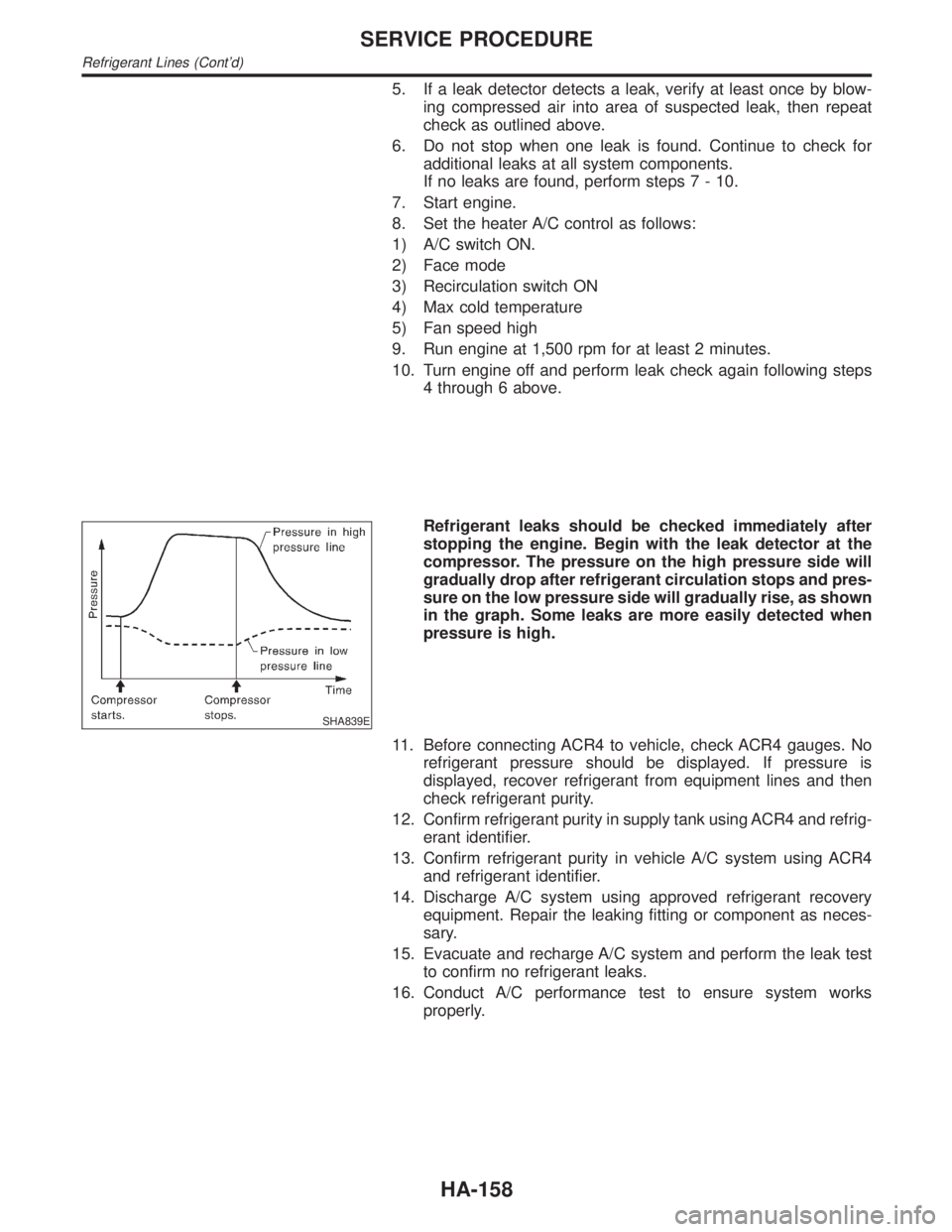
Refrigerant leaks should be checked immediately after
stopping the engine. Begin with the leak detector at the
compressor. The pressure on the high pressure side will
gradually drop after refrigerant circulation stops and pres-
sure on the low pressure side will gradually rise, as shown
in the graph. Some leaks are more easily detected when
pressure is high.
11. Before connecting ACR4 to vehicle, check ACR4 gauges. No
refrigerant pressure should be displayed. If pressure is
displayed, recover refrigerant from equipment lines and then
check refrigerant purity.
12. Confirm refrigerant purity in supply tank using ACR4 and refrig-
erant identifier.
13. Confirm refrigerant purity in vehicle A/C system using ACR4
and refrigerant identifier.
14. Discharge A/C system using approved refrigerant recovery
equipment. Repair the leaking fitting or component as neces-
sary.
15. Evacuate and recharge A/C system and perform the leak test
to confirm no refrigerant leaks.
16. Conduct A/C performance test to ensure system works
properly.
SERVICE PROCEDURE
Refrigerant Lines (Cont'd)
HA-158