Page 2142 of 2395
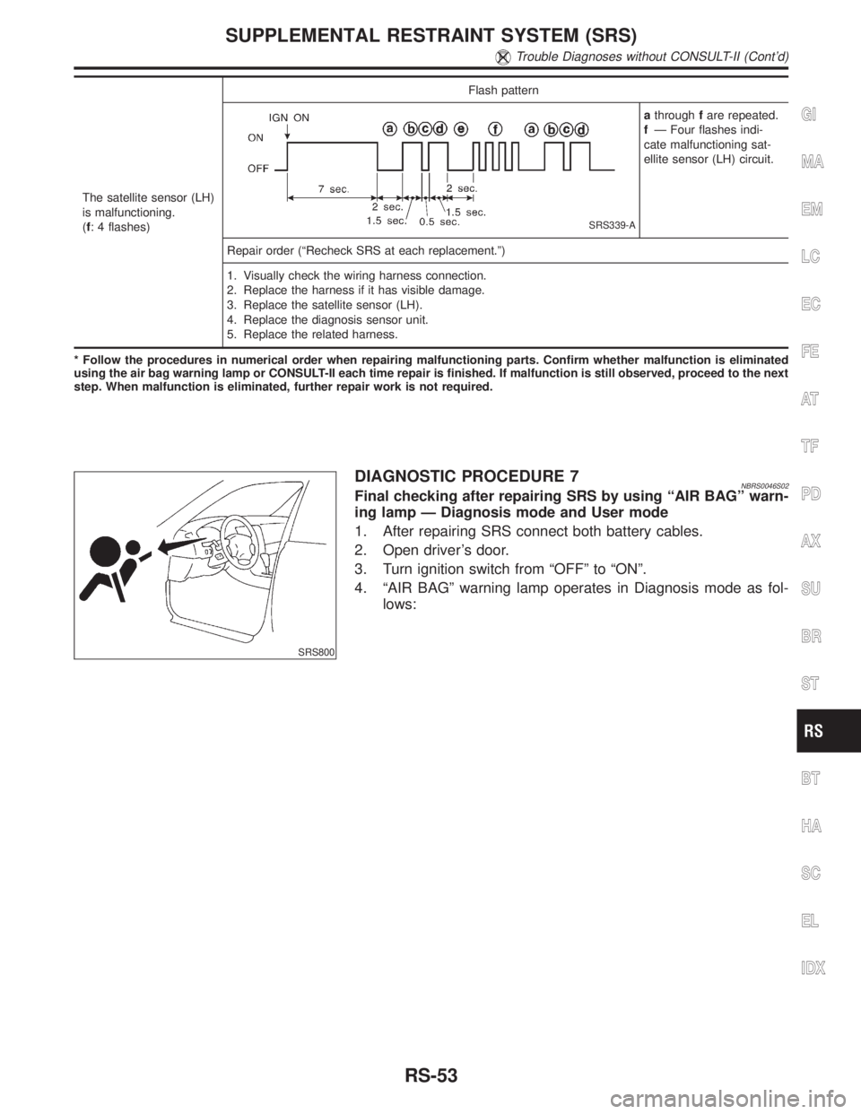
The satellite sensor (LH)
is malfunctioning.
(f: 4 flashes)Flash pattern
SRS339-A
athroughfare repeated.
fÐ Four flashes indi-
cate malfunctioning sat-
ellite sensor (LH) circuit.
Repair order (ªRecheck SRS at each replacement.º)
1. Visually check the wiring harness connection.
2. Replace the harness if it has visible damage.
3. Replace the satellite sensor (LH).
4. Replace the diagnosis sensor unit.
5. Replace the related harness.
* Follow the procedures in numerical order when repairing malfunctioning parts. Confirm whether malfunction is eliminated
using the air bag warning lamp or CONSULT-II each time repair is finished. If malfunction is still observed, proceed to the next
step. When malfunction is eliminated, further repair work is not required.
SRS800
DIAGNOSTIC PROCEDURE 7NBRS0046S02Final checking after repairing SRS by using ªAIR BAGº warn-
ing lamp Ð Diagnosis mode and User mode
1. After repairing SRS connect both battery cables.
2. Open driver's door.
3. Turn ignition switch from ªOFFº to ªONº.
4. ªAIR BAGº warning lamp operates in Diagnosis mode as fol-
lows:
GI
MA
EM
LC
EC
FE
AT
TF
PD
AX
SU
BR
ST
BT
HA
SC
EL
IDX
SUPPLEMENTAL RESTRAINT SYSTEM (SRS)
Trouble Diagnoses without CONSULT-II (Cont'd)
RS-53
Page 2157 of 2395
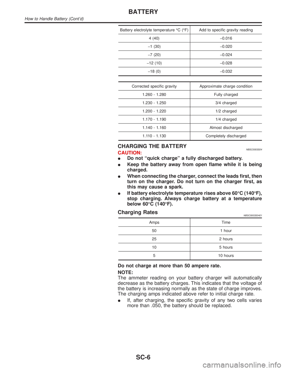
Battery electrolyte temperature ÉC (ÉF) Add to specific gravity reading
4 (40) þ0.016
þ1 (30) þ0.020
þ7 (20) þ0.024
þ12 (10) þ0.028
þ18 (0) þ0.032
Corrected specific gravity Approximate charge condition
1.260 - 1.280 Fully charged
1.230 - 1.250 3/4 charged
1.200 - 1.220 1/2 charged
1.170 - 1.190 1/4 charged
1.140 - 1.160 Almost discharged
1.110 - 1.130 Completely discharged
CHARGING THE BATTERYNBSC0003S04CAUTION:
IDo not ªquick chargeº a fully discharged battery.
IKeep the battery away from open flame while it is being
charged.
IWhen connecting the charger, connect the leads first, then
turn on the charger. Do not turn on the charger first, as
this may cause a spark.
IIf battery electrolyte temperature rises above 60ÉC (140ÉF),
stop charging. Always charge battery at a temperature
below 60ÉC (140ÉF).
Charging RatesNBSC0003S0401
Amps Time
50 1 hour
25 2 hours
10 5 hours
5 10 hours
Do not charge at more than 50 ampere rate.
NOTE:
The ammeter reading on your battery charger will automatically
decrease as the battery charges. This indicates that the voltage of
the battery is increasing normally as the state of charge improves.
The charging amps indicated above refer to initial charge rate.
IIf, after charging, the specific gravity of any two cells varies
more than .050, the battery should be replaced.
BATTERY
How to Handle Battery (Cont'd)
SC-6
Page 2160 of 2395
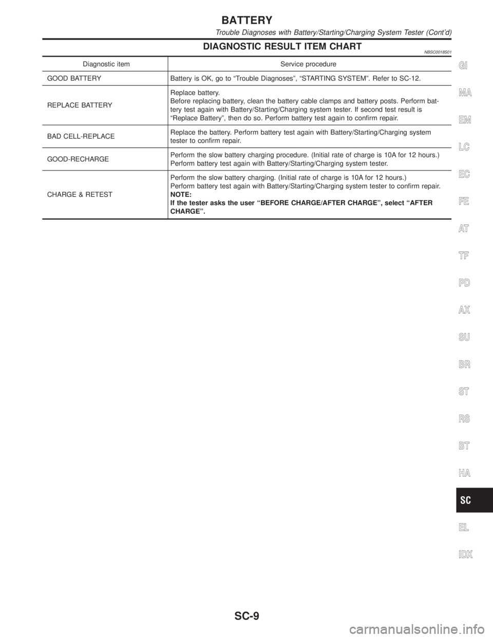
DIAGNOSTIC RESULT ITEM CHARTNBSC0018S01
Diagnostic item Service procedure
GOOD BATTERY Battery is OK, go to ªTrouble Diagnosesº, ªSTARTING SYSTEMº. Refer to SC-12.
REPLACE BATTERYReplace battery.
Before replacing battery, clean the battery cable clamps and battery posts. Perform bat-
tery test again with Battery/Starting/Charging system tester. If second test result is
ªReplace Batteryº, then do so. Perform battery test again to confirm repair.
BAD CELL-REPLACEReplace the battery. Perform battery test again with Battery/Starting/Charging system
tester to confirm repair.
GOOD-RECHARGEPerform the slow battery charging procedure. (Initial rate of charge is 10A for 12 hours.)
Perform battery test again with Battery/Starting/Charging system tester.
CHARGE & RETESTPerform the slow battery charging. (Initial rate of charge is 10A for 12 hours.)
Perform battery test again with Battery/Starting/Charging system tester to confirm repair.
NOTE:
If the tester asks the user ªBEFORE CHARGE/AFTER CHARGEº, select ªAFTER
CHARGEº.GI
MA
EM
LC
EC
FE
AT
TF
PD
AX
SU
BR
ST
RS
BT
HA
EL
IDX
BATTERY
Trouble Diagnoses with Battery/Starting/Charging System Tester (Cont'd)
SC-9
Page 2164 of 2395
DIAGNOSTIC RESULT ITEM CHARTNBSC0019S01
Diagnostic item Service procedure
CRANKING VOLTAGE NORMAL Go to ªWORK FLOWº, SC-14.
CRANKING VOLTAGE LOW Go to ªWORK FLOWº, SC-14.
CHARGE BATTERYPerform the slow battery charging procedure. (Initial rate of charge is 10A for 12 hours.)
Perform battery test again with Battery/Starting/Charging system tester. Refer to SC-7.
REPLACE BATTERYBefore replacing battery, clean the battery cable clamps and battery posts. Perform bat-
tery test again with Battery/Starting/Charging system tester. Refer to SC-7. If second test
result is ªREPLACE BATTERYº, then do so. Perform battery test again to confirm repair.GI
MA
EM
LC
EC
FE
AT
TF
PD
AX
SU
BR
ST
RS
BT
HA
EL
IDX
STARTING SYSTEM
Trouble Diagnoses with Battery/Starting/Charging System Tester (Cont'd)
SC-13
Page 2174 of 2395
DIAGNOSTIC RESULT ITEM CHARTNBSC0020S01
Diagnostic item Service procedure
CHARGING SYSTEM NORMAL Charging system is normal and will also show DIODE RIPPLE test result.
NO CHARGING VOLTAGE Go to ªWORK FLOWº, SC-24.
LOW CHARGING VOLTAGE Go to ªWORK FLOWº, SC-24.
HIGH CHARGING VOLTAGE Go to ªWORK FLOWº, SC-24.
DIODE RIPPLE NORMAL Diode ripple is OK and will also show CHARGING VOLTAGE test result.
EXCESS RIPPLE DETECTEDReplace the alternator. Perform ªDIODE RIPPLEº test again using Battery/Starting/
Charging system tester to confirm repair.
DIODE RIPPLE NOT DETECTED Go to ªWORK FLOWº, SC-24.GI
MA
EM
LC
EC
FE
AT
TF
PD
AX
SU
BR
ST
RS
BT
HA
EL
IDX
CHARGING SYSTEM
Trouble Diagnoses with Battery/Starting/Charging System Tester (Cont'd)
SC-23
Page 2176 of 2395
DIAGNOSTIC PROCEDURE 1NBSC0020S03Check ªLº Terminal CircuitNBSC0020S0301
1 CHECK ªLº TERMINAL CONNECTION
Check to see if ªLº terminal is clean and tight.
OK or NG
OK©GO TO 2.
NG©Repair ªLº terminal connection. Confirm repair by performing complete Battery/Starting/
Charging system test.
2 CHECK ªLº TERMINAL CIRCUIT
1. Disconnect E106 connector from alternator.
2. Apply ground to E106 connector terminal 1 with the ignition switch in the ON position.
SEL424X
OK or NG
OK©Replace the alternator. Confirm repair by performing complete Battery/Starting/Charging
system test.
NG©Check the following.
I10A fuse [No. 8, located in fuse block (J/B)]
ICHARGE lamp
IHarness for open or short between combination meter and fuse
IHarness for open or short between combination meter and alternator
GI
MA
EM
LC
EC
FE
AT
TF
PD
AX
SU
BR
ST
RS
BT
HA
EL
IDX
CHARGING SYSTEM
Trouble Diagnoses with Battery/Starting/Charging System Tester (Cont'd)
SC-25
Page 2177 of 2395
DIAGNOSTIC PROCEDURE 2=NBSC0020S04Check ªBº Terminal CircuitNBSC0020S0401
1 CHECK ªBº TERMINAL CONNECTION
Check to see if ªBº terminal is clean and tight.
OK or NG
OK©GO TO 2. Confirm repair by performing complete Battery/Starting/Charging system test.
NG©Repair ªBº terminal connection.
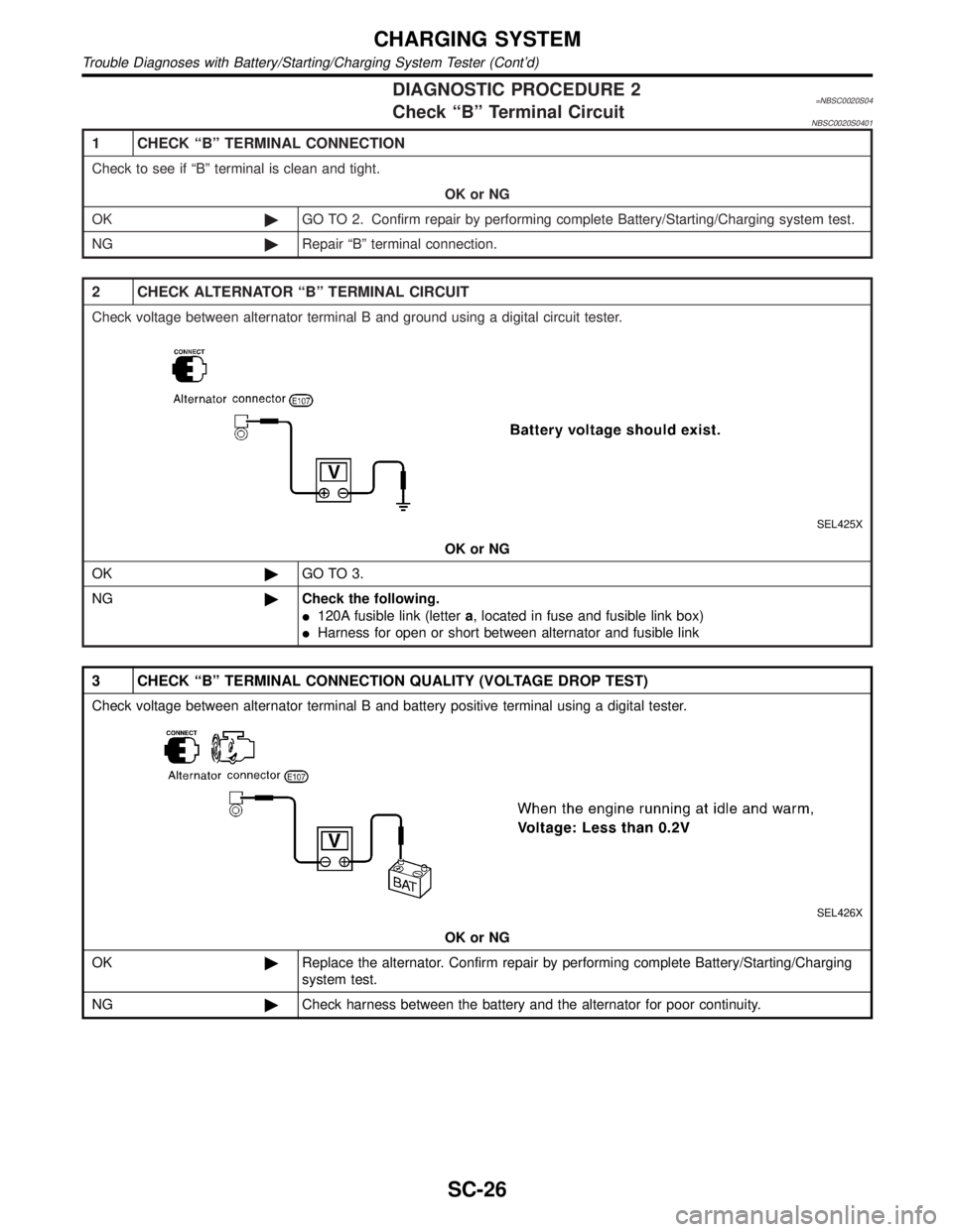
2 CHECK ALTERNATOR ªBº TERMINAL CIRCUIT
Check voltage between alternator terminal B and ground using a digital circuit tester.
SEL425X
OK or NG
OK©GO TO 3.
NG©Check the following.
I120A fusible link (lettera, located in fuse and fusible link box)
IHarness for open or short between alternator and fusible link
3 CHECK ªBº TERMINAL CONNECTION QUALITY (VOLTAGE DROP TEST)
Check voltage between alternator terminal B and battery positive terminal using a digital tester.
SEL426X
OK or NG
OK©Replace the alternator. Confirm repair by performing complete Battery/Starting/Charging
system test.
NG©Check harness between the battery and the alternator for poor continuity.
CHARGING SYSTEM
Trouble Diagnoses with Battery/Starting/Charging System Tester (Cont'd)
SC-26
Page 2178 of 2395
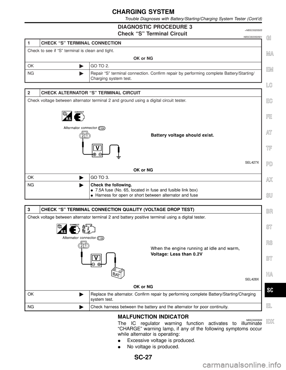
DIAGNOSTIC PROCEDURE 3=NBSC0020S05Check ªSº Terminal CircuitNBSC0020S0501
1 CHECK ªSº TERMINAL CONNECTION
Check to see if ªSº terminal is clean and tight.
OK or NG
OK©GO TO 2.
NG©Repair ªSº terminal connection. Confirm repair by performing complete Battery/Starting/
Charging system test.
2 CHECK ALTERNATOR ªSº TERMINAL CIRCUIT
Check voltage between alternator terminal 2 and ground using a digital circuit tester.
SEL427X
OK or NG
OK©GO TO 3.
NG©Check the following.
I7.5A fuse (No. 65, located in fuse and fusible link box)
IHarness for open or short between alternator and fuse
3 CHECK ªSº TERMINAL CONNECTION QUALITY (VOLTAGE DROP TEST)
Check voltage between alternator terminal 2 and battery positive terminal using a digital tester.
SEL428X
OK or NG
OK©Replace the alternator. Confirm repair by performing complete Battery/Starting/Charging
system test.
NG©Check harness between the battery and the alternator for poor continuity.
MALFUNCTION INDICATORNBSC0020S06The IC regulator warning function activates to illuminate
ªCHARGEº warning lamp, if any of the following symptoms occur
while alternator is operating:
IExcessive voltage is produced.
INo voltage is produced.
GI
MA
EM
LC
EC
FE
AT
TF
PD
AX
SU
BR
ST
RS
BT
HA
EL
IDX
CHARGING SYSTEM
Trouble Diagnoses with Battery/Starting/Charging System Tester (Cont'd)
SC-27