Page 1575 of 2395
FUNCTION OF TOUCH SWITCH (SUMMARY)=NBEL0228S03Display with Pushed ªMAPº SwitchNBEL0228S0301
SEL580X
The function of each touch switch is as follows:
1) Azimuth indication
2) Position marker
The tip of the arrow shows the current position. The shaft of
the arrow indicates the direction in which the vehicle is travel-
ing.
3) GPS reception signal (indicates current reception conditions)
4) Distance display (shows the distance in a reduced scale)
5) Current location voice information
(this information is available when the route guide is being
activated and the designated route is being traveled.)
6) Switch display from map screen to BIRDVIEW
Tscreen
(change to map screen on display when the BIRDVIEWTis
being used.)
7) The following items can be set.
ISave Current Location
IEdit Address Book
IGuide Volume
ISystem Setting
8) The route guide operation can be canceled.
NAVIGATION SYSTEM
System Description (Cont'd)
EL-390
Page 1576 of 2395
Display with Pushed ªDESTº Switch=NBEL0228S0302
SEL581X
The function of each touch switch is as follows:
Icon Description
Address Book Favorite place can be saved to memory.
The destination can be selected from the memory.
Address/Street The destination can be searched from the address.
Point of Interest (POI) The destination of favorite facility can be searched.
Previous Dest. The previous ten destinations stored in memory are
displayed.
Intersection The destination from the intersection name can be
retrieved.
City The destination can be searched from city name.
Map The destination can be searched from the map.
GI
MA
EM
LC
EC
FE
AT
TF
PD
AX
SU
BR
ST
RS
BT
HA
SC
IDX
NAVIGATION SYSTEM
System Description (Cont'd)
EL-391
Page 1577 of 2395

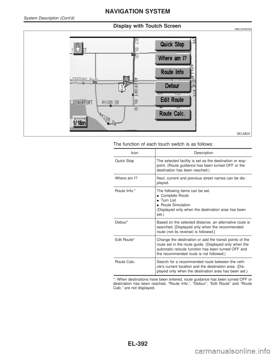
Display with Toutch ScreenNBEL0228S0303
SEL582X
The function of each touch switch is as follows:
Icon Description
Quick Stop The selected facility is set as the destination or way-
point. (Route guidance has been turned OFF or the
destination has been reached.)
Where am I? Next, current and previous street names can be dis-
played.
Route Info.* The following items can be set.
IComplete Route
ITurn List
IRoute Simulation
(Displayed only when the destination area has been
set.)
Detour* Based on the selected distance, an alternative route is
searched. [Displayed only when the recommended
route (not its reverse) is followed.]
Edit Route* Change the destination or add the transit points of the
route set in the route guide. (Displayed only when the
automatic reroute function has been turned OFF and
the recommended route is not followed.)
Route Calc. Search for a recommended route between the vehi-
cle's current location and the destination area. (Dis-
played only when the destination area has been set.)
*: When destinations have been entered, route guidance has been turned OFF or
destination has been reached, ªRoute Info.º, ªDetourº, ªEdit Routeº and ªRoute
Calc.º are not displayed.
NAVIGATION SYSTEM
System Description (Cont'd)
EL-392
Page 1578 of 2395
SchematicNBEL0229
MEL268M
GI
MA
EM
LC
EC
FE
AT
TF
PD
AX
SU
BR
ST
RS
BT
HA
SC
IDX
NAVIGATION SYSTEM
Schematic
EL-393
Page 1579 of 2395
Wiring Diagram Ð NAVI ÐNBEL0230
MEL823L
NAVIGATION SYSTEM
Wiring Diagram Ð NAVI Ð
EL-394
Page 1580 of 2395
MEL269M
GI
MA
EM
LC
EC
FE
AT
TF
PD
AX
SU
BR
ST
RS
BT
HA
SC
IDX
NAVIGATION SYSTEM
Wiring Diagram Ð NAVI Ð (Cont'd)
EL-395
Page 1581 of 2395
MEL270M
NAVIGATION SYSTEM
Wiring Diagram Ð NAVI Ð (Cont'd)
EL-396
Page 1582 of 2395

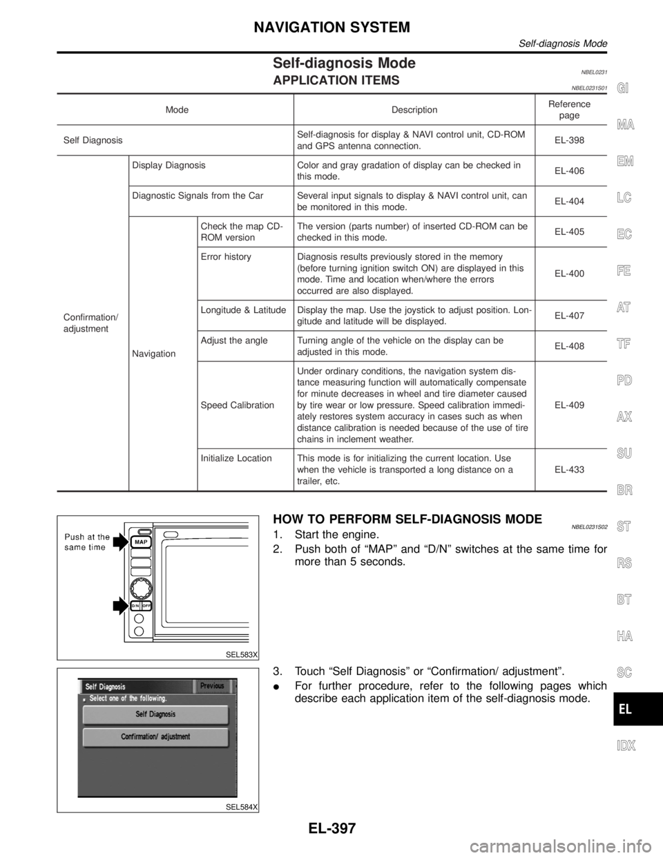
Self-diagnosis ModeNBEL0231APPLICATION ITEMSNBEL0231S01
Mode DescriptionReference
page
Self DiagnosisSelf-diagnosis for display & NAVI control unit, CD-ROM
and GPS antenna connection.EL-398
Confirmation/
adjustmentDisplay Diagnosis Color and gray gradation of display can be checked in
this mode.EL-406
Diagnostic Signals from the Car Several input signals to display & NAVI control unit, can
be monitored in this mode.EL-404
NavigationCheck the map CD-
ROM versionThe version (parts number) of inserted CD-ROM can be
checked in this mode.EL-405
Error history Diagnosis results previously stored in the memory
(before turning ignition switch ON) are displayed in this
mode. Time and location when/where the errors
occurred are also displayed.EL-400
Longitude & Latitude Display the map. Use the joystick to adjust position. Lon-
gitude and latitude will be displayed.EL-407
Adjust the angle Turning angle of the vehicle on the display can be
adjusted in this mode.EL-408
Speed CalibrationUnder ordinary conditions, the navigation system dis-
tance measuring function will automatically compensate
for minute decreases in wheel and tire diameter caused
by tire wear or low pressure. Speed calibration immedi-
ately restores system accuracy in cases such as when
distance calibration is needed because of the use of tire
chains in inclement weather.EL-409
Initialize Location This mode is for initializing the current location. Use
when the vehicle is transported a long distance on a
trailer, etc.EL-433
SEL583X
HOW TO PERFORM SELF-DIAGNOSIS MODENBEL0231S021. Start the engine.
2. Push both of ªMAPº and ªD/Nº switches at the same time for
more than 5 seconds.
SEL584X
3. Touch ªSelf Diagnosisº or ªConfirmation/ adjustmentº.
IFor further procedure, refer to the following pages which
describe each application item of the self-diagnosis mode.
GI
MA
EM
LC
EC
FE
AT
TF
PD
AX
SU
BR
ST
RS
BT
HA
SC
IDX
NAVIGATION SYSTEM
Self-diagnosis Mode
EL-397