Page 922 of 2395

8 CHECK EVAP CONTROL SYSTEM PRESSURE SENSOR INPUT SIGNAL CIRCUIT FOR OPEN AND
SHORT
1. Disconnect ECM harness connector.
2. Check harness continuity between ECM terminal 84 and EVAP control system pressure sensor terminal 2.
Refer to Wiring Diagram.
Continuity should exist.
3. Also check harness for short to ground and short to power.
OK or NG
OK (With CONSULT-II)©GO TO 10.
OK (Without CONSULT-
II)©GO TO 11.
NG©GO TO 9.
9 DETECT MALFUNCTIONING PART
Check the following.
IHarness connectors B101, B43
IHarness connectors B1, M2 and M94, F27
IHarness for open or short between ECM and EVAP control system pressure sensor
©Repair open circuit or short to ground or short to power in harness or connectors.
10 CHECK EVAP CANISTER PURGE VOLUME CONTROL SOLENOID VALVE
With CONSULT-II
1. Start engine.
2. Perform ªPURG VOL CONT/Vº in ªACTIVE TESTº mode with CONSULT-II. Check that engine speed varies according
to the valve opening.
SEF985Y
OK or NG
OK©GO TO 12.
NG©GO TO 11.
GI
MA
EM
LC
FE
AT
TF
PD
AX
SU
BR
ST
RS
BT
HA
SC
EL
IDX
DTC P0450 EVAPORATIVE EMISSION (EVAP) CONTROL SYSTEM PRESSURE
SENSOR
Diagnostic Procedure (Cont'd)
EC-387
Page 931 of 2395

SEF565X
DTC Confirmation ProcedureNBEC0646
SEF566X
SEF874X
SEF567X
CAUTION:
Never remove fuel filler cap during the DTC Confirmation Pro-
cedure.
NOTE:
IIf DTC P0455 is displayed with P1448, perform trouble
diagnosis for DTC P1448 first. (See EC-573.)
IMake sure that EVAP hoses are connected to EVAP canis-
ter purge volume control solenoid valve properly.
IIf ªDTC Confirmation Procedureº has been previously
conducted, always turn ignition switch ªOFFº and wait at least
10 seconds before conducting the next test.
TESTING CONDITION:
IPerform ªDTC WORK SUPPORTº when the fuel level is
between 1/4 to 3/4 full and vehicle is placed on flat level
surface.
IOpen engine hood before conducting the following proce-
dures.
WITH CONSULT-IINBEC0646S011) Tighten fuel filler cap securely until ratcheting sound is heard.
2) Turn ignition switch ªONº.
3) Turn ignition switch ªOFFº and wait at least 10 seconds.
4) Turn ignition switch ªONº and select ªDATA MONITORº mode
with CONSULT-II.
5) Make sure that the following conditions are met.
COOLAN TEMP/S: 0 - 70ÉC (32 - 158ÉF)
INT/A TEMP SE: 0 - 60ÉC (32 - 140ÉF)
6) Select ªEVAP SML LEAK P0440/P1440º of ªEVAPORATIVE
SYSTEMº in ªDTC WORK SUPPORTº mode with CONSULT-
II.
Follow the instruction displayed.
NOTE:
If the engine speed cannot be maintained within the range dis-
played on the CONSULT-II screen, go to ªBasic Inspectionº,
EC-101.
7) Make sure that ªOKº is displayed.
If ªNGº is displayed, select ªSELF-DIAG RESULTSº mode and
make sure that ªEVAP GROSS LEAK [P0455]º is displayed. If
it is displayed, refer to ªDiagnostic Procedureº, EC-397.
If P0440 is displayed, perform ªDiagnostic Procedureº for DTC
P0440.
WITH GSTNBEC0646S02NOTE:
Be sure to read the explanation of ªDriving Patternº on EC-66
before driving vehicle.
1) Start engine.
2) Drive vehicle according to ªDriving Patternº, EC-66.
3) Stop vehicle.
4) Select ªMODE 1º with GST.
IIf SRT of EVAP system is not set yet, go to the following step.
IIf SRT of EVAP system is set, the result will be OK.
5) Turn ignition switch ªOFFº and wait at least 10 seconds.
6) Start engine.
It is not necessary to cool engine down before driving.
7) Drive vehicle again according to the ªDriving Patternº, EC-66.
DTC P0455 EVAP CONTROL SYSTEM (GROSS LEAK)
DTC Confirmation Procedure
EC-396
Page 937 of 2395

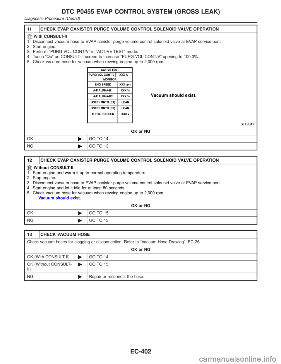
11 CHECK EVAP CANISTER PURGE VOLUME CONTROL SOLENOID VALVE OPERATION
With CONSULT-II
1. Disconnect vacuum hose to EVAP canister purge volume control solenoid valve at EVAP service port.
2. Start engine.
3. Perform ªPURG VOL CONT/Vº in ªACTIVE TESTº mode.
4. Touch ªQuº on CONSULT-II screen to increase ªPURG VOL CONT/Vº opening to 100.0%.
5. Check vacuum hose for vacuum when revving engine up to 2,000 rpm.
SEF984Y
OK or NG
OK©GO TO 14.
NG©GO TO 13.
12 CHECK EVAP CANISTER PURGE VOLUME CONTROL SOLENOID VALVE OPERATION
Without CONSULT-II
1. Start engine and warm it up to normal operating temperature.
2. Stop engine.
3. Disconnect vacuum hose to EVAP canister purge volume control solenoid valve at EVAP service port.
4. Start engine and let it idle for at least 80 seconds.
5. Check vacuum hose for vacuum when revving engine up to 2,000 rpm.
Vacuum should exist.
OK or NG
OK©GO TO 15.
NG©GO TO 13.
13 CHECK VACUUM HOSE
Check vacuum hoses for clogging or disconnection. Refer to ªVacuum Hose Drawingº, EC-26.
OK or NG
OK (With CONSULT-II)©GO TO 14.
OK (Without CONSULT-
II)©GO TO 15.
NG©Repair or reconnect the hose.
DTC P0455 EVAP CONTROL SYSTEM (GROSS LEAK)
Diagnostic Procedure (Cont'd)
EC-402
Page 938 of 2395
14 CHECK EVAP CANISTER PURGE VOLUME CONTROL SOLENOID VALVE
With CONSULT-II
1. Start engine.
2. Perform ªPURG VOL CONT/Vº in ªACTIVE TESTº mode with CONSULT-II. Check that engine speed varies according
to the valve opening.
SEF985Y
OK or NG
OK©GO TO 16.
NG©GO TO 15.
GI
MA
EM
LC
FE
AT
TF
PD
AX
SU
BR
ST
RS
BT
HA
SC
EL
IDX
DTC P0455 EVAP CONTROL SYSTEM (GROSS LEAK)
Diagnostic Procedure (Cont'd)
EC-403
Page 940 of 2395

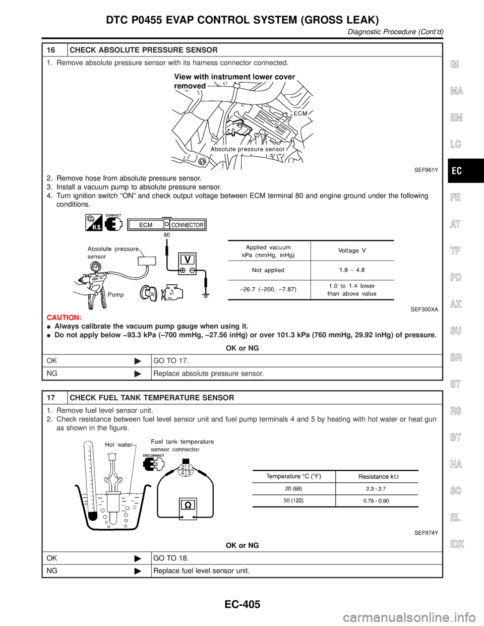
16 CHECK ABSOLUTE PRESSURE SENSOR
1. Remove absolute pressure sensor with its harness connector connected.
SEF961Y
2. Remove hose from absolute pressure sensor.
3. Install a vacuum pump to absolute pressure sensor.
4. Turn ignition switch ªONº and check output voltage between ECM terminal 80 and engine ground under the following
conditions.
SEF300XA
CAUTION:
IAlways calibrate the vacuum pump gauge when using it.
IDo not apply below þ93.3 kPa (±700 mmHg, ±27.56 inHg) or over 101.3 kPa (760 mmHg, 29.92 inHg) of pressure.
OK or NG
OK©GO TO 17.
NG©Replace absolute pressure sensor.
17 CHECK FUEL TANK TEMPERATURE SENSOR
1. Remove fuel level sensor unit.
2. Check resistance between fuel level sensor unit and fuel pump terminals 4 and 5 by heating with hot water or heat gun
as shown in the figure.
SEF974Y
OK or NG
OK©GO TO 18.
NG©Replace fuel level sensor unit.
GI
MA
EM
LC
FE
AT
TF
PD
AX
SU
BR
ST
RS
BT
HA
SC
EL
IDX
DTC P0455 EVAP CONTROL SYSTEM (GROSS LEAK)
Diagnostic Procedure (Cont'd)
EC-405
Page 942 of 2395

SEF018S
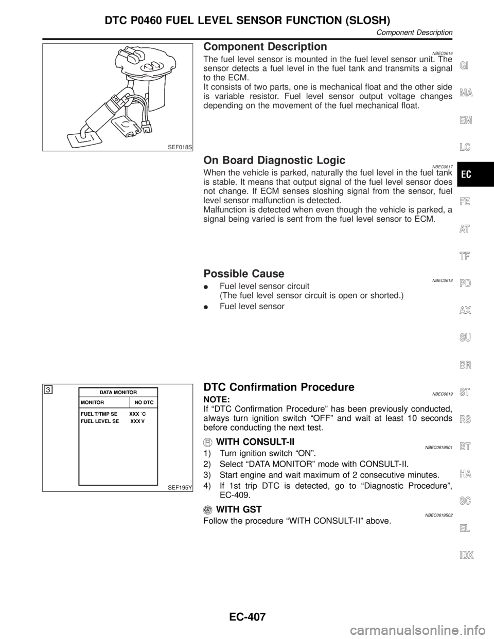
Component DescriptionNBEC0616The fuel level sensor is mounted in the fuel level sensor unit. The
sensor detects a fuel level in the fuel tank and transmits a signal
to the ECM.
It consists of two parts, one is mechanical float and the other side
is variable resistor. Fuel level sensor output voltage changes
depending on the movement of the fuel mechanical float.
On Board Diagnostic LogicNBEC0617When the vehicle is parked, naturally the fuel level in the fuel tank
is stable. It means that output signal of the fuel level sensor does
not change. If ECM senses sloshing signal from the sensor, fuel
level sensor malfunction is detected.
Malfunction is detected when even though the vehicle is parked, a
signal being varied is sent from the fuel level sensor to ECM.
Possible CauseNBEC0618IFuel level sensor circuit
(The fuel level sensor circuit is open or shorted.)
IFuel level sensor
SEF195Y
DTC Confirmation ProcedureNBEC0619NOTE:
If ªDTC Confirmation Procedureº has been previously conducted,
always turn ignition switch ªOFFº and wait at least 10 seconds
before conducting the next test.
WITH CONSULT-IINBEC0619S011) Turn ignition switch ªONº.
2) Select ªDATA MONITORº mode with CONSULT-II.
3) Start engine and wait maximum of 2 consecutive minutes.
4) If 1st trip DTC is detected, go to ªDiagnostic Procedureº,
EC-409.
WITH GSTNBEC0619S02Follow the procedure ªWITH CONSULT-IIº above.
GI
MA
EM
LC
FE
AT
TF
PD
AX
SU
BR
ST
RS
BT
HA
SC
EL
IDX
DTC P0460 FUEL LEVEL SENSOR FUNCTION (SLOSH)
Component Description
EC-407
Page 952 of 2395

AEC110
Component Description=NBEC0242The vehicle speed sensor is installed in the transaxle. It contains a
pulse generator which provides a vehicle speed signal to the
speedometer. The speedometer then sends a signal to the ECM.
ECM Terminals and Reference ValueNBEC0669Specification data are reference values and are measured between each terminal and ground.
CAUTION:
Do not use ECM ground terminals when measuring input/output voltage. Doing so may result in dam-
age to the ECM's transistor. Use a ground other than ECM terminals, such as the ground.
TERMI-
NAL
NO.WIRE
COLORITEM CONDITION DATA (DC Voltage)
86 W/L Vehicle speed sensor[Engine is running]
IJack up front wheels.
IIn 1st gear position
I10 km/h (6 MPH)Approximately 2.5V
SEF583X
[Engine is running]
IJack up front wheels.
IIn 2nd gear position
I30 km/h (19 MPH)Approximately 2.0V
SEF584X
On Board Diagnosis LogicNBEC0244Malfunction is detected when the almost 0 km/h (0 MPH) signal
from vehicle speed sensor is sent to ECM even when vehicle is
being driven.
GI
MA
EM
LC
FE
AT
TF
PD
AX
SU
BR
ST
RS
BT
HA
SC
EL
IDX
DTC P0500 VEHICLE SPEED SENSOR (VSS)
Component Description
EC-417
Page 953 of 2395

Possible CauseNBEC0514IHarness or connector
(The vehicle speed sensor circuit is open or shorted.)
IVehicle speed sensor
DTC Confirmation ProcedureNBEC0245CAUTION:
Always drive vehicle at a safe speed.
NOTE:
If ªDTC Confirmation Procedureº has been previously conducted,
always turn ignition switch ªOFFº and wait at least 10 seconds
before conducting the next test.
TESTING CONDITION:
Steps 1 and 2 may be conducted with the drive wheels lifted
in the shop or by driving the vehicle. If a road test is expected
to be easier, it is unnecessary to lift the vehicle.
SEF196Y
WITH CONSULT-IINBEC0245S011) Start engine (TCS switch ªOFFº).
2) Read ªVHCL SPEED SEº in ªDATA MONITORº mode with
CONSULT-II. The vehicle speed on CONSULT-II should
exceed 10 km/h (6 MPH) when rotating wheels with suitable
gear position.
If NG, go to ªDiagnostic Procedureº, EC-421.
If OK, go to following step.
3) Select ªDATA MONITORº mode with CONSULT-II.
4) Warm engine up to normal operating temperature.
5) Maintain the following conditions for at least 10 consecutive
seconds.
ENG SPEED 1,800 - 6,000 rpm
COOLAN TEMP/S More than 70ÉC (158ÉF)
B/FUEL SCHDL 5.5 - 14.0 msec
Selector lever Suitable position
PW/ST SIGNAL OFF
6) If 1st trip DTC is detected, go to ªDiagnostic Procedureº,
EC-421.
Overall Function CheckNBEC0246Use this procedure to check the overall function of the vehicle
speed sensor circuit. During this check, a 1st trip DTC might not
be confirmed.
WITH GSTNBEC0246S011) Lift up drive wheels.
2) Start engine.
3) Read vehicle speed sensor signal in ªMODE 1º with GST.
The vehicle speed sensor on GST should be able to exceed
DTC P0500 VEHICLE SPEED SENSOR (VSS)
Possible Cause
EC-418