Page 682 of 2395
12 CHECK ECM POWER SUPPLY CIRCUIT-IV
1. Disconnect ECM relay.
SEF681UB
2. Check voltage between ECM relay terminal 7 and ground with CONSULT-II or tester.
SEF957Y
OK or NG
OK©GO TO 14.
NG©GO TO 13.
13 DETECT MALFUNCTIONING PART
Check the following.
IHarness for open or short between ECM relay and 7.5A fuse
©Repair open circuit or short to ground or short to power in harness or connectors.
14 CHECK ECM POWER SUPPLY-V
1. Turn ignition switch ªOFFº and then ªONº.
2. Check voltage between ECM terminal 12 and ground with CONSULT-II or tester.
SEF331Z
OK or NG
OK©GO TO 16.
NG©GO TO 15.
GI
MA
EM
LC
FE
AT
TF
PD
AX
SU
BR
ST
RS
BT
HA
SC
EL
IDX
TROUBLE DIAGNOSIS FOR POWER SUPPLY
Main Power Supply and Ground Circuit (Cont'd)
EC-147
Page 683 of 2395

15 DETECT MALFUNCTIONING PART
Check the following.
IHarness connectors E1, M1
IHarness connectors M94, F27
I10A fuse
©Repair harness or connectors.
16 CHECK HARNESS CONTINUITY BETWEEN ECM RELAY AND ECM FOR OPEN AND SHORT
1. Check harness continuity between ECM terminals 110, 112 and ECM relay terminal 6.
Refer to WIRING DIAGRAM.
Continuity should exist.
2. Also check harness for short to ground and short to power.
OK or NG
OK©GO TO 18.
NG©GO TO 17.
17 DETECT MALFUNCTIONING PART
Check the following.
IHarness connectors E1, M1 and M32, F23
IHarness for open or short between ECM and ECM relay
©Repair open circuit or short to ground or short to power in harness or connectors.
18 CHECK ECM RELAY
1. Apply 12V direct current between ECM relay terminals 1 and 2.
2. Check continuity between relay terminals 3 and 5, 6 and 7.
SEF296X
OK or NG
OK©GO TO 19.
NG©Replace ECM relay.
19 CHECK ECM GROUND CIRCUIT FOR OPEN AND SHORT-II
1. Turn ignition switch ªOFFº.
2. Disconnect ECM harness connector.
3. Check harness continuity between ECM terminals 48, 57, 106, 108 and engine ground.
Refer to WIRING DIAGRAM.
Continuity should exist.
4. Also check harness for short to ground and short to power.
OK or NG
OK©GO TO 20.
NG©Repair open circuit or short to ground or short to power in harness or connectors.
TROUBLE DIAGNOSIS FOR POWER SUPPLY
Main Power Supply and Ground Circuit (Cont'd)
EC-148
Page 691 of 2395
4 CHECK MAFS POWER SUPPLY CIRCUIT
1. Disconnect mass air flow sensor (MAFS) harness connector.
SEF960Y
2. Turn ignition switch ªONº.
3. Check voltage between MAFS terminals 2, 4 and ground with CONSULT-II or tester.
SEF297X
OK or NG
OK©GO TO 6.
NG©GO TO 5.
5 DETECT MALFUNCTIONING PART
Check the following.
IHarness for open or short between ECM relay and mass air flow sensor
IHarness for open or short between mass air flow sensor and ECM
©Repair harness or connectors.
6 CHECK MAFS GROUND CIRCUIT FOR OPEN AND SHORT
1. Turn ignition switch ªOFFº.
2. Disconnect ECM harness connector.
3. Check harness continuity between MAFS terminal 3 and ECM terminal 73.
Refer to Wiring Diagram.
Continuity should exist.
4. Also check harness for short to power.
OK or NG
OK©GO TO 7.
NG©Repair open circuit or short to power in harness or connectors.
DTC P0100 MASS AIR FLOW SENSOR (MAFS)
Diagnostic Procedure (Cont'd)
EC-156
Page 874 of 2395

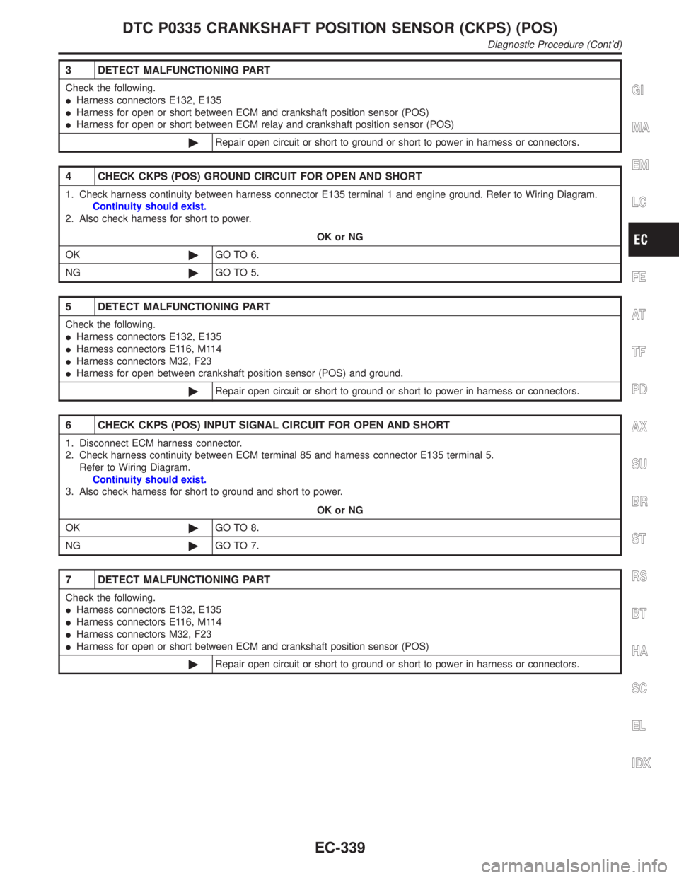
3 DETECT MALFUNCTIONING PART
Check the following.
IHarness connectors E132, E135
IHarness for open or short between ECM and crankshaft position sensor (POS)
IHarness for open or short between ECM relay and crankshaft position sensor (POS)
©Repair open circuit or short to ground or short to power in harness or connectors.
4 CHECK CKPS (POS) GROUND CIRCUIT FOR OPEN AND SHORT
1. Check harness continuity between harness connector E135 terminal 1 and engine ground. Refer to Wiring Diagram.
Continuity should exist.
2. Also check harness for short to power.
OK or NG
OK©GO TO 6.
NG©GO TO 5.
5 DETECT MALFUNCTIONING PART
Check the following.
IHarness connectors E132, E135
IHarness connectors E116, M114
IHarness connectors M32, F23
IHarness for open between crankshaft position sensor (POS) and ground.
©Repair open circuit or short to ground or short to power in harness or connectors.
6 CHECK CKPS (POS) INPUT SIGNAL CIRCUIT FOR OPEN AND SHORT
1. Disconnect ECM harness connector.
2. Check harness continuity between ECM terminal 85 and harness connector E135 terminal 5.
Refer to Wiring Diagram.
Continuity should exist.
3. Also check harness for short to ground and short to power.
OK or NG
OK©GO TO 8.
NG©GO TO 7.
7 DETECT MALFUNCTIONING PART
Check the following.
IHarness connectors E132, E135
IHarness connectors E116, M114
IHarness connectors M32, F23
IHarness for open or short between ECM and crankshaft position sensor (POS)
©Repair open circuit or short to ground or short to power in harness or connectors.
GI
MA
EM
LC
FE
AT
TF
PD
AX
SU
BR
ST
RS
BT
HA
SC
EL
IDX
DTC P0335 CRANKSHAFT POSITION SENSOR (CKPS) (POS)
Diagnostic Procedure (Cont'd)
EC-339
Page 961 of 2395
Diagnostic ProcedureNBEC0255
1 CHECK IACV-AAC VALVE POWER SUPPLY CIRCUIT
1. Stop engine.
2. Disconnect IACV-AAC valve harness connector.
SEF994Y
3. Turn ignition switch ªONº.
4. Check voltage between IACV-AAC valve terminals 2, 5 and ground with CONSULT-II or tester.
SEF343X
OK or NG
OK©GO TO 3.
NG©GO TO 2.
2 DETECT MALFUNCTIONING PART
Check the following.
IHarness connectors E1, M1
IHarness connectors M33, F22
IHarness for open or short between IACV-AAC valve and ECM relay
©Repair harness or connectors.
DTC P0505 IDLE AIR CONTROL VALVE (IACV) Ð AUXILIARY AIR CONTROL
(AAC) VALVE
Diagnostic Procedure
EC-426
Page 1023 of 2395

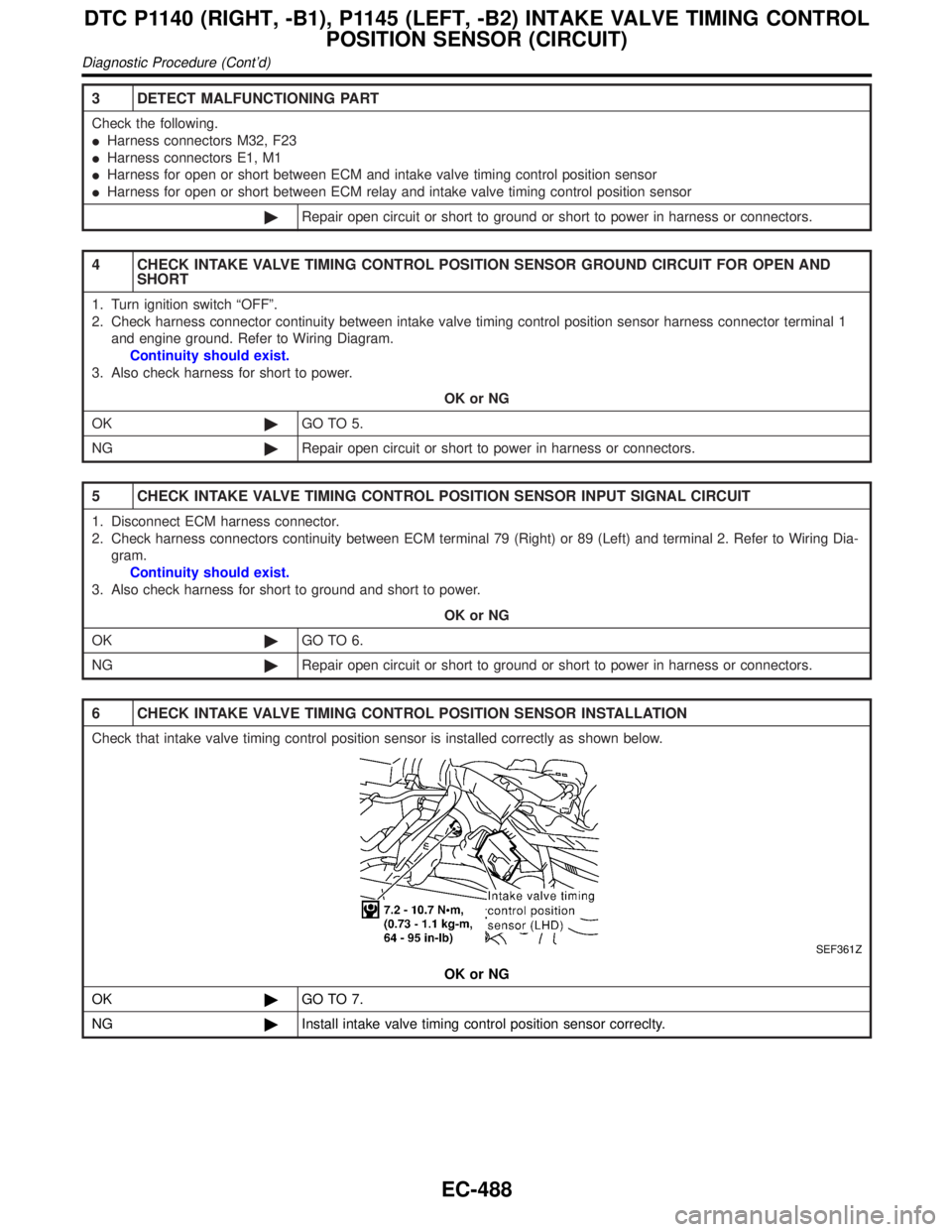
3 DETECT MALFUNCTIONING PART
Check the following.
IHarness connectors M32, F23
IHarness connectors E1, M1
IHarness for open or short between ECM and intake valve timing control position sensor
IHarness for open or short between ECM relay and intake valve timing control position sensor
©Repair open circuit or short to ground or short to power in harness or connectors.
4 CHECK INTAKE VALVE TIMING CONTROL POSITION SENSOR GROUND CIRCUIT FOR OPEN AND
SHORT
1. Turn ignition switch ªOFFº.
2. Check harness connector continuity between intake valve timing control position sensor harness connector terminal 1
and engine ground. Refer to Wiring Diagram.
Continuity should exist.
3. Also check harness for short to power.
OK or NG
OK©GO TO 5.
NG©Repair open circuit or short to power in harness or connectors.
5 CHECK INTAKE VALVE TIMING CONTROL POSITION SENSOR INPUT SIGNAL CIRCUIT
1. Disconnect ECM harness connector.
2. Check harness connectors continuity between ECM terminal 79 (Right) or 89 (Left) and terminal 2. Refer to Wiring Dia-
gram.
Continuity should exist.
3. Also check harness for short to ground and short to power.
OK or NG
OK©GO TO 6.
NG©Repair open circuit or short to ground or short to power in harness or connectors.
6 CHECK INTAKE VALVE TIMING CONTROL POSITION SENSOR INSTALLATION
Check that intake valve timing control position sensor is installed correctly as shown below.
SEF361Z
OK or NG
OK©GO TO 7.
NG©Install intake valve timing control position sensor correclty.
DTC P1140 (RIGHT, -B1), P1145 (LEFT, -B2) INTAKE VALVE TIMING CONTROL
POSITION SENSOR (CIRCUIT)
Diagnostic Procedure (Cont'd)
EC-488
Page 1040 of 2395
4 CHECK IGNITION COIL POWER SUPPLY CIRCUIT-II
1. Turn ignition switch OFF.
2. Disconnect condenser harness connector.
SEF008Z
3. Turn ignition switch ON.
4. Check voltage between condenser terminal 1 and ground with CONSULT-II or tester.
SEF367X
OK or NG
OK©GO TO 10.
NG©GO TO 5.
5 CHECK IGNITION COIL POWER SUPPLY CIRCUIT-III
1. Turn ignition switch OFF.
2. Disconnect ECM relay.
SEF009Z
3. Check harness continuity between ECM relay terminal 3 and condenser terminal 1. Refer to Wiring Diagram.
Continuity should exist.
4. Also check harness for short to ground and short to power.
OK or NG
OK©GO TO 7.
NG©GO TO 6.
GI
MA
EM
LC
FE
AT
TF
PD
AX
SU
BR
ST
RS
BT
HA
SC
EL
IDX
DTC P1320 IGNITION SIGNAL
Diagnostic Procedure (Cont'd)
EC-505
Page 1041 of 2395
6 DETECT MALFUNCTIONING PART
Check the following.
IHarness connectors E1, M1 and M33, F22
IHarness for open or short between ECM relay and condenser
©Repair open circuit or short to ground or short to power in harness or connectors.
7 CHECK IGNITION COIL POWER SUPPLY CIRCUIT-IV
Check voltage between ECM relay terminal 5 and ground with CONSULT-II or tester.
SEF010Z
OK or NG
OK©GO TO 9.
NG©GO TO 8.
8 DETECT MALFUNCTIONING PART
Check the following.
I10A fuse
IHarness for open and short between ECM relay and fuse
©Repair or replace harness or connectors.
9 CHECK ECM RELAY
1. Apply 12V direct current between ECM relay terminals 1 and 2.
2. Check continuity between ECM relay terminals 3 and 5, 6 and 7.
SEF296X
OK or NG
OK©GO TO 17.
NG©Replace ECM relay.
DTC P1320 IGNITION SIGNAL
Diagnostic Procedure (Cont'd)
EC-506