2001 INFINITI QX4 oil temperature
[x] Cancel search: oil temperaturePage 666 of 2395
![INFINITI QX4 2001 Factory Service Manual TERMI-
NAL
NO.WIRE
COLORITEM CONDITION DATA (DC Voltage)
42 B/Y Start signal[Ignition switch ªONº]Approximately 0V
[Ignition switch ªSTARTº]9 - 12V
43 R Ignition switch[Ignition switch ªOFFº]0V](/manual-img/42/57027/w960_57027-665.png "INFINITI QX4 2001 Factory Service Manual TERMI-
NAL
NO.WIRE
COLORITEM CONDITION DATA (DC Voltage)
42 B/Y Start signal[Ignition switch ªONº]Approximately 0V
[Ignition switch ªSTARTº]9 - 12V
43 R Ignition switch[Ignition switch ªOFFº]0V")
TERMI-
NAL
NO.WIRE
COLORITEM CONDITION DATA (DC Voltage)
42 B/Y Start signal[Ignition switch ªONº]Approximately 0V
[Ignition switch ªSTARTº]9 - 12V
43 R Ignition switch[Ignition switch ªOFFº]0V
[Ignition switch ªONº]BATTERY VOLTAGE
(11 - 14V)
44 L PNP switch[Ignition switch ªONº]
IGear position is ªPº or ªNº.Approximately 0V
[Ignition switch ªONº]
IExcept the above gear positionBATTERY VOLTAGE
(11 - 14V)
45 B/RAir conditioner switch
signal[Engine is running]
IBoth A/C switch and blower switch are ªONº.Approximately 0V
[Engine is running]
IA/C switch is ªOFFº.Approximately 5V
47 R/BPower steering oil
pressure switch[Engine is running]
ISteering wheel is being turned.0 - 1.0V
[Engine is running]
ISteering wheel is not being turned.Approximately 5V
48 B ECM ground[Engine is running]
IIdle speedEngine ground
51 BR A/C cut signal[Engine is running]
IAir conditioner is operating.0 - 0.5V
52 PU Electrical load signal[Engine is running]
IRear window defogger: ON
IHi-beam headlamp: ONBATTERY VOLTAGE
(11 - 14V)
[Engine is running]
IElectrical load: OFF0V
55 W/BSwirl control valve con-
trol vacuum check
switch[Engine is running]
IIdle speed
IEngine coolant temperature is between 15 to
50ÉC (59 to 122ÉF).Approximately 5V
[Engine is running]
IIdle speed
IEngine coolant temperature is above 55ÉC
(131ÉF).0 - 1.0V
56 OR/LThrottle position switch
(Closed position)[Engine is running]
IAccelerator pedal fully releasedBATTERY VOLTAGE
(11 - 14V)
[Engine is running]
IAccelerator pedal depressedApproximately 0V
57 B ECM ground[Engine is running]
IIdle speedEngine ground
58 B/P Sensors' ground[Engine is running]
IWarm-up condition
IIdle speedApproximately 0V
59 BFuel level sensor
ground[Engine is running]
IIdle speedApproximately 0V
GI
MA
EM
LC
FE
AT
TF
PD
AX
SU
BR
ST
RS
BT
HA
SC
EL
IDX
TROUBLE DIAGNOSIS Ð GENERAL DESCRIPTION
ECM Terminals and Reference Value (Cont'd)
EC-131
Page 957 of 2395
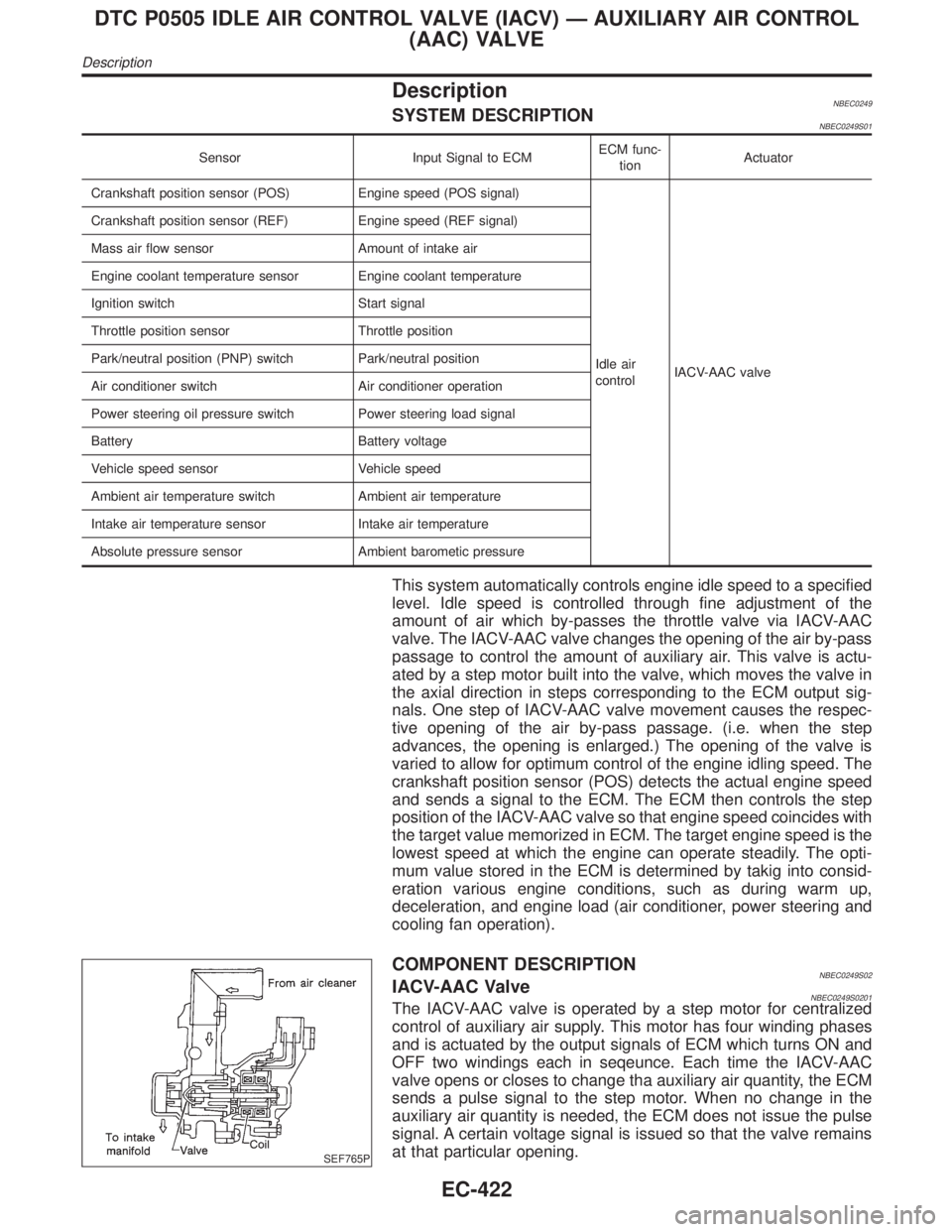
DescriptionNBEC0249SYSTEM DESCRIPTIONNBEC0249S01
Sensor Input Signal to ECMECM func-
tionActuator
Crankshaft position sensor (POS) Engine speed (POS signal)
Idle air
controlIACV-AAC valve Crankshaft position sensor (REF) Engine speed (REF signal)
Mass air flow sensor Amount of intake air
Engine coolant temperature sensor Engine coolant temperature
Ignition switch Start signal
Throttle position sensor Throttle position
Park/neutral position (PNP) switch Park/neutral position
Air conditioner switch Air conditioner operation
Power steering oil pressure switch Power steering load signal
Battery Battery voltage
Vehicle speed sensor Vehicle speed
Ambient air temperature switch Ambient air temperature
Intake air temperature sensor Intake air temperature
Absolute pressure sensor Ambient barometic pressure
This system automatically controls engine idle speed to a specified
level. Idle speed is controlled through fine adjustment of the
amount of air which by-passes the throttle valve via IACV-AAC
valve. The IACV-AAC valve changes the opening of the air by-pass
passage to control the amount of auxiliary air. This valve is actu-
ated by a step motor built into the valve, which moves the valve in
the axial direction in steps corresponding to the ECM output sig-
nals. One step of IACV-AAC valve movement causes the respec-
tive opening of the air by-pass passage. (i.e. when the step
advances, the opening is enlarged.) The opening of the valve is
varied to allow for optimum control of the engine idling speed. The
crankshaft position sensor (POS) detects the actual engine speed
and sends a signal to the ECM. The ECM then controls the step
position of the IACV-AAC valve so that engine speed coincides with
the target value memorized in ECM. The target engine speed is the
lowest speed at which the engine can operate steadily. The opti-
mum value stored in the ECM is determined by takig into consid-
eration various engine conditions, such as during warm up,
deceleration, and engine load (air conditioner, power steering and
cooling fan operation).
SEF765P
COMPONENT DESCRIPTIONNBEC0249S02IACV-AAC ValveNBEC0249S0201The IACV-AAC valve is operated by a step motor for centralized
control of auxiliary air supply. This motor has four winding phases
and is actuated by the output signals of ECM which turns ON and
OFF two windings each in seqeunce. Each time the IACV-AAC
valve opens or closes to change tha auxiliary air quantity, the ECM
sends a pulse signal to the step motor. When no change in the
auxiliary air quantity is needed, the ECM does not issue the pulse
signal. A certain voltage signal is issued so that the valve remains
at that particular opening.
DTC P0505 IDLE AIR CONTROL VALVE (IACV) Ð AUXILIARY AIR CONTROL
(AAC) VALVE
Description
EC-422
Page 1642 of 2395
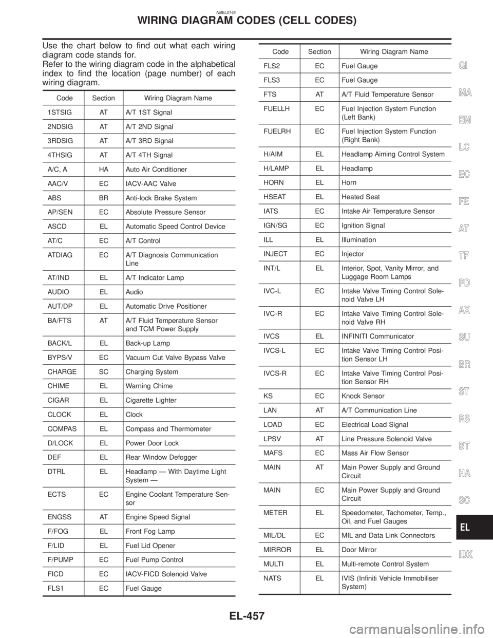
NBEL0145
Use the chart below to find out what each wiring
diagram code stands for.
Refer to the wiring diagram code in the alphabetical
index to find the location (page number) of each
wiring diagram.
Code Section Wiring Diagram Name
1STSIG AT A/T 1ST Signal
2NDSIG AT A/T 2ND Signal
3RDSIG AT A/T 3RD Signal
4THSIG AT A/T 4TH Signal
A/C, A HA Auto Air Conditioner
AAC/V EC IACV-AAC Valve
ABS BR Anti-lock Brake System
AP/SEN EC Absolute Pressure Sensor
ASCD EL Automatic Speed Control Device
AT/C EC A/T Control
ATDIAG EC A/T Diagnosis Communication
Line
AT/IND EL A/T Indicator Lamp
AUDIO EL Audio
AUT/DP EL Automatic Drive Positioner
BA/FTS AT A/T Fluid Temperature Sensor
and TCM Power Supply
BACK/L EL Back-up Lamp
BYPS/V EC Vacuum Cut Valve Bypass Valve
CHARGE SC Charging System
CHIME EL Warning Chime
CIGAR EL Cigarette Lighter
CLOCK EL Clock
COMPAS EL Compass and Thermometer
D/LOCK EL Power Door Lock
DEF EL Rear Window Defogger
DTRL EL Headlamp Ð With Daytime Light
System Ð
ECTS EC Engine Coolant Temperature Sen-
sor
ENGSS AT Engine Speed Signal
F/FOG EL Front Fog Lamp
F/LID EL Fuel Lid Opener
F/PUMP EC Fuel Pump Control
FICD EC IACV-FICD Solenoid Valve
FLS1 EC Fuel Gauge
Code Section Wiring Diagram Name
FLS2 EC Fuel Gauge
FLS3 EC Fuel Gauge
FTS AT A/T Fluid Temperature Sensor
FUELLH EC Fuel Injection System Function
(Left Bank)
FUELRH EC Fuel Injection System Function
(Right Bank)
H/AIM EL Headlamp Aiming Control System
H/LAMP EL Headlamp
HORN EL Horn
HSEAT EL Heated Seat
IATS EC Intake Air Temperature Sensor
IGN/SG EC Ignition Signal
ILL EL Illumination
INJECT EC Injector
INT/L EL Interior, Spot, Vanity Mirror, and
Luggage Room Lamps
IVC-L EC Intake Valve Timing Control Sole-
noid Valve LH
IVC-R EC Intake Valve Timing Control Sole-
noid Valve RH
IVCS EL INFINITI Communicator
IVCS-L EC Intake Valve Timing Control Posi-
tion Sensor LH
IVCS-R EC Intake Valve Timing Control Posi-
tion Sensor RH
KS EC Knock Sensor
LAN AT A/T Communication Line
LOAD EC Electrical Load Signal
LPSV AT Line Pressure Solenoid Valve
MAFS EC Mass Air Flow Sensor
MAIN AT Main Power Supply and Ground
Circuit
MAIN EC Main Power Supply and Ground
Circuit
METER EL Speedometer, Tachometer, Temp.,
Oil, and Fuel Gauges
MIL/DL EC MIL and Data Link Connectors
MIRROR EL Door Mirror
MULTI EL Multi-remote Control System
NATS EL IVIS (Infiniti Vehicle Immobiliser
System)
GI
MA
EM
LC
EC
FE
AT
TF
PD
AX
SU
BR
ST
RS
BT
HA
SC
IDX
WIRING DIAGRAM CODES (CELL CODES)
EL-457
Page 1643 of 2395
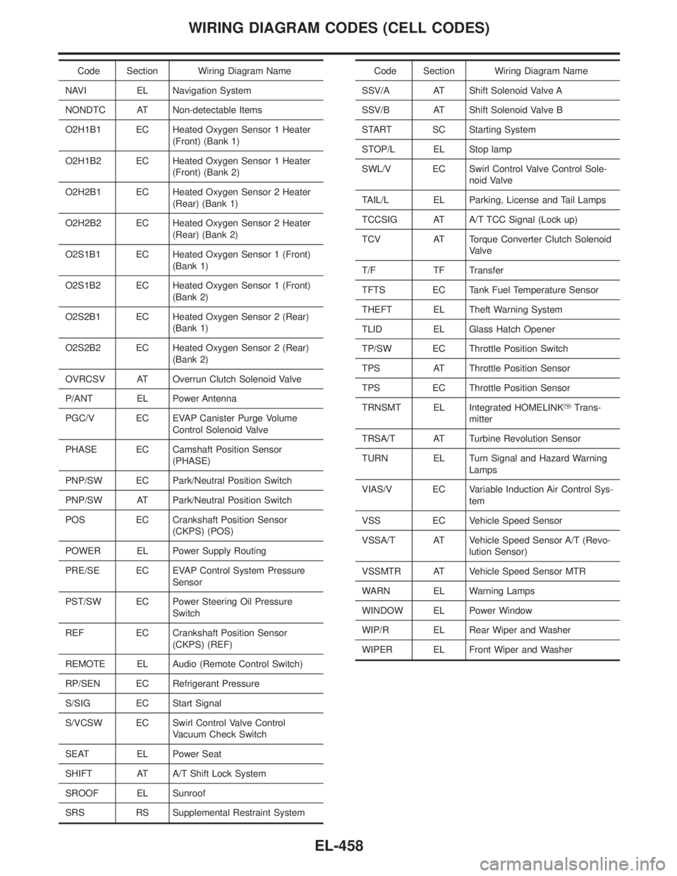
Code Section Wiring Diagram Name
NAVI EL Navigation System
NONDTC AT Non-detectable Items
O2H1B1 EC Heated Oxygen Sensor 1 Heater
(Front) (Bank 1)
O2H1B2 EC Heated Oxygen Sensor 1 Heater
(Front) (Bank 2)
O2H2B1 EC Heated Oxygen Sensor 2 Heater
(Rear) (Bank 1)
O2H2B2 EC Heated Oxygen Sensor 2 Heater
(Rear) (Bank 2)
O2S1B1 EC Heated Oxygen Sensor 1 (Front)
(Bank 1)
O2S1B2 EC Heated Oxygen Sensor 1 (Front)
(Bank 2)
O2S2B1 EC Heated Oxygen Sensor 2 (Rear)
(Bank 1)
O2S2B2 EC Heated Oxygen Sensor 2 (Rear)
(Bank 2)
OVRCSV AT Overrun Clutch Solenoid Valve
P/ANT EL Power Antenna
PGC/V EC EVAP Canister Purge Volume
Control Solenoid Valve
PHASE EC Camshaft Position Sensor
(PHASE)
PNP/SW EC Park/Neutral Position Switch
PNP/SW AT Park/Neutral Position Switch
POS EC Crankshaft Position Sensor
(CKPS) (POS)
POWER EL Power Supply Routing
PRE/SE EC EVAP Control System Pressure
Sensor
PST/SW EC Power Steering Oil Pressure
Switch
REF EC Crankshaft Position Sensor
(CKPS) (REF)
REMOTE EL Audio (Remote Control Switch)
RP/SEN EC Refrigerant Pressure
S/SIG EC Start Signal
S/VCSW EC Swirl Control Valve Control
Vacuum Check Switch
SEAT EL Power Seat
SHIFT AT A/T Shift Lock System
SROOF EL Sunroof
SRS RS Supplemental Restraint SystemCode Section Wiring Diagram Name
SSV/A AT Shift Solenoid Valve A
SSV/B AT Shift Solenoid Valve B
START SC Starting System
STOP/L EL Stop lamp
SWL/V EC Swirl Control Valve Control Sole-
noid Valve
TAIL/L EL Parking, License and Tail Lamps
TCCSIG AT A/T TCC Signal (Lock up)
TCV AT Torque Converter Clutch Solenoid
Valve
T/F TF Transfer
TFTS EC Tank Fuel Temperature Sensor
THEFT EL Theft Warning System
TLID EL Glass Hatch Opener
TP/SW EC Throttle Position Switch
TPS AT Throttle Position Sensor
TPS EC Throttle Position Sensor
TRNSMT EL Integrated HOMELINKYTrans-
mitter
TRSA/T AT Turbine Revolution Sensor
TURN EL Turn Signal and Hazard Warning
Lamps
VIAS/V EC Variable Induction Air Control Sys-
tem
VSS EC Vehicle Speed Sensor
VSSA/T AT Vehicle Speed Sensor A/T (Revo-
lution Sensor)
VSSMTR AT Vehicle Speed Sensor MTR
WARN EL Warning Lamps
WINDOW EL Power Window
WIP/R EL Rear Wiper and Washer
WIPER EL Front Wiper and Washer
WIRING DIAGRAM CODES (CELL CODES)
EL-458
Page 1726 of 2395
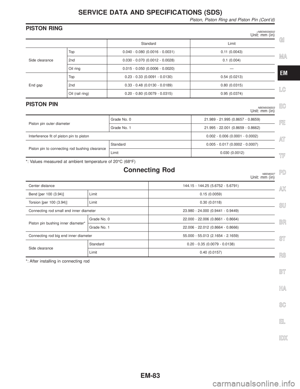
PISTON RING=NBEM0036S02Unit: mm (in)
Standard Limit
Side clearanceTop 0.040 - 0.080 (0.0016 - 0.0031) 0.11 (0.0043)
2nd 0.030 - 0.070 (0.0012 - 0.0028) 0.1 (0.004)
Oil ring 0.015 - 0.050 (0.0006 - 0.0020) Ð
End gapTop 0.23 - 0.33 (0.0091 - 0.0130) 0.54 (0.0213)
2nd 0.33 - 0.48 (0.0130 - 0.0189) 0.80 (0.0315)
Oil (rail ring) 0.20 - 0.80 (0.0079 - 0.0315) 0.95 (0.0374)
PISTON PINNBEM0036S03Unit: mm (in)
Piston pin outer diameterGrade No. 0 21.989 - 21.995 (0.8657 - 0.8659)
Grade No. 1 21.995 - 22.001 (0.8659 - 0.8662)
Interference fit of piston pin to piston 0.002 - 0.006 (0.0001 - 0.0002)
Piston pin to connecting rod bushing clearanceStandard 0.005 - 0.017 (0.0002 - 0.0007)
Limit 0.030 (0.0012)
*: Values measured at ambient temperature of 20ÉC (68ÉF)
Connecting RodNBEM0037Unit: mm (in)
Center distance144.15 - 144.25 (5.6752 - 5.6791)
Bend [per 100 (3.94)] Limit 0.15 (0.0059)
Torsion [per 100 (3.94)] Limit 0.30 (0.0118)
Connecting rod small end inner diameter 23.980 - 24.000 (0.9441 - 0.9449)
Piston pin bushing inner diameter*Grade No. 0 22.000 - 22.006 (0.8661 - 0.8664)
Grade No. 1 22.006 - 22.012 (0.8664 - 0.8666)
Connecting rod big end inner diameter 55.000 - 55.013 (2.1654 - 2.1659)
Side clearanceStandard 0.20 - 0.35 (0.0079 - 0.0138)
Limit 0.40 (0.0157)
*: After installing in connecting rod
GI
MA
LC
EC
FE
AT
TF
PD
AX
SU
BR
ST
RS
BT
HA
SC
EL
IDX
SERVICE DATA AND SPECIFICATIONS (SDS)
Piston, Piston Ring and Piston Pin (Cont'd)
EM-83
Page 1751 of 2395
IClean all disassembled parts in the designated liquid or solvent
prior to inspection or assembly.
IReplace oil seals, gaskets, packings, O-rings, locking washers,
cotter pins, self-locking nuts, etc. with new ones.
IReplace inner and outer races of tapered roller bearings and
needle bearings as a set.
IArrange the disassembled parts in accordance with their
assembled locations and sequence.
IDo not touch the terminals of electrical components which use
microcomputers (such as ECMs).
Static electricity may damage internal electronic components.
IAfter disconnecting vacuum or air hoses, attach a tag to indi-
cate the proper connection.
IUse only the fluids and lubricants specified in this manual.
IUse approved bonding agent, sealants or their equivalents
when required.
IUse tools and recommended special tools where specified for
safe and efficient service repairs.
IWhen repairing the fuel, oil, water, vacuum or exhaust
systems, check all affected lines for leaks.
IDispose of drained oil or the solvent used for cleaning parts in
an appropriate manner.
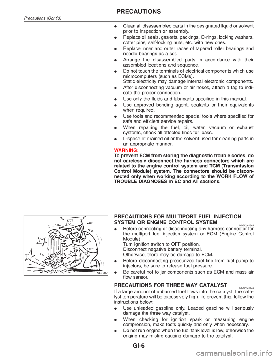
WARNING:
To prevent ECM from storing the diagnostic trouble codes, do
not carelessly disconnect the harness connectors which are
related to the engine control system and TCM (Transmission
Control Module) system. The connectors should be discon-
nected only when working according to the WORK FLOW of
TROUBLE DIAGNOSES in EC and AT sections.
SGI787
PRECAUTIONS FOR MULTIPORT FUEL INJECTION
SYSTEM OR ENGINE CONTROL SYSTEM
NBGI0001S03IBefore connecting or disconnecting any harness connector for
the multiport fuel injection system or ECM (Engine Control
Module):
Turn ignition switch to OFF position.
Disconnect negative battery terminal.
Otherwise, there may be damage to ECM.
IBefore disconnecting pressurized fuel line from fuel pump to
injectors, be sure to release fuel pressure.
IBe careful not to jar components such as ECM and mass air
flow sensor.
PRECAUTIONS FOR THREE WAY CATALYSTNBGI0001S04If a large amount of unburned fuel flows into the catalyst, the cata-
lyst temperature will be excessively high. To prevent this, follow the
instructions below:
IUse unleaded gasoline only. Leaded gasoline will seriously
damage the three way catalyst.
IWhen checking for ignition spark or measuring engine
compression, make tests quickly and only when necessary.
IDo not run engine when the fuel tank level is low, otherwise the
engine may misfire causing damage to the catalyst.
PRECAUTIONS
Precautions (Cont'd)
GI-6
Page 1805 of 2395
CAUTION:
When replacing or cleaning refrigerant cycle components, observe the following.
IWhen the compressor is removed, store it in the same position as it is when mounted on the car.
Failure to do so will cause lubricant to enter the low pressure chamber.
IWhen connecting tubes, always use a torque wrench and a back-up wrench.
IAfter disconnecting tubes, immediately plug all openings to prevent entry of dirt and moisture.
IWhen installing an air conditioner in the vehicle, connect the pipes as the final stage of the opera-
tion. Do not remove the seal caps of pipes and other components until just before required for
connection.
IAllow components stored in cool areas to warm to working area temperature before removing seal
caps. This prevents condensation from forming inside A/C components.
IThoroughly remove moisture from the refrigeration system before charging the refrigerant.
IAlways replace used O-rings.
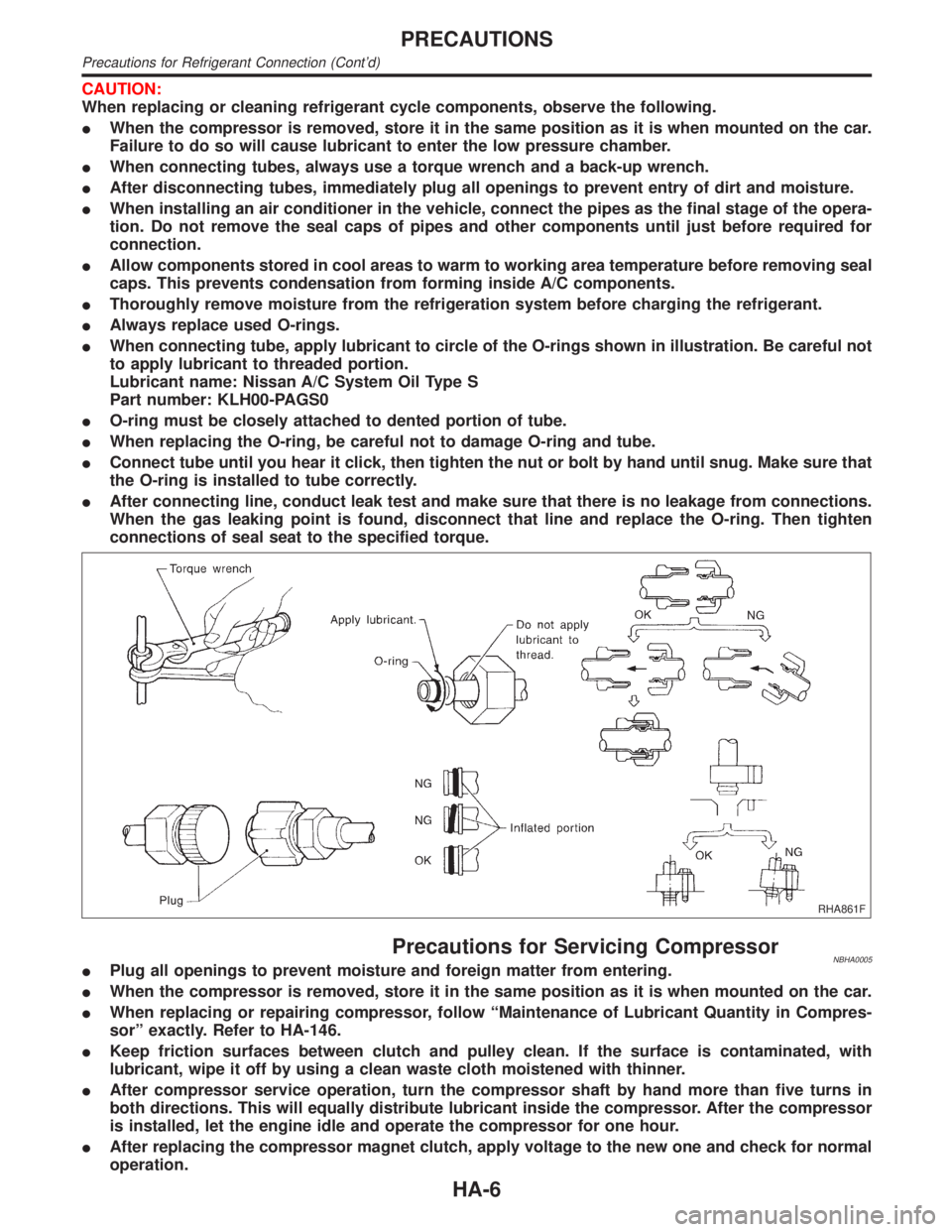
IWhen connecting tube, apply lubricant to circle of the O-rings shown in illustration. Be careful not
to apply lubricant to threaded portion.
Lubricant name: Nissan A/C System Oil Type S
Part number: KLH00-PAGS0
IO-ring must be closely attached to dented portion of tube.
IWhen replacing the O-ring, be careful not to damage O-ring and tube.
IConnect tube until you hear it click, then tighten the nut or bolt by hand until snug. Make sure that
the O-ring is installed to tube correctly.
IAfter connecting line, conduct leak test and make sure that there is no leakage from connections.
When the gas leaking point is found, disconnect that line and replace the O-ring. Then tighten
connections of seal seat to the specified torque.
RHA861F
Precautions for Servicing CompressorNBHA0005IPlug all openings to prevent moisture and foreign matter from entering.
IWhen the compressor is removed, store it in the same position as it is when mounted on the car.
IWhen replacing or repairing compressor, follow ªMaintenance of Lubricant Quantity in Compres-
sorº exactly. Refer to HA-146.
IKeep friction surfaces between clutch and pulley clean. If the surface is contaminated, with
lubricant, wipe it off by using a clean waste cloth moistened with thinner.
IAfter compressor service operation, turn the compressor shaft by hand more than five turns in
both directions. This will equally distribute lubricant inside the compressor. After the compressor
is installed, let the engine idle and operate the compressor for one hour.
IAfter replacing the compressor magnet clutch, apply voltage to the new one and check for normal
operation.
PRECAUTIONS
Precautions for Refrigerant Connection (Cont'd)
HA-6
Page 1813 of 2395
Refrigeration System
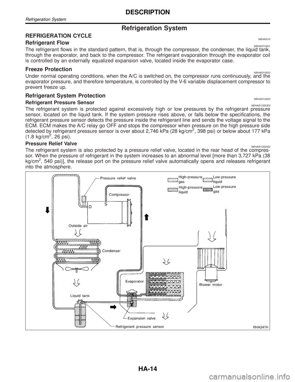
REFRIGERATION CYCLENBHA0010Refrigerant FlowNBHA0010S01The refrigerant flows in the standard pattern, that is, through the compressor, the condenser, the liquid tank,
through the evaporator, and back to the compressor. The refrigerant evaporation through the evaporator coil
is controlled by an externally equalized expansion valve, located inside the evaporator case.
Freeze ProtectionNBHA0010S02Under normal operating conditions, when the A/C is switched on, the compressor runs continuously, and the
evaporator pressure, and therefore temperature, is controlled by the V-6 variable displacement compressor to
prevent freeze up.
Refrigerant System ProtectionNBHA0010S03Refrigerant Pressure SensorNBHA0010S0303The refrigerant system is protected against excessively high or low pressures by the refrigerant pressure
sensor, located on the liquid tank. If the system pressure rises above, or falls below the specifications, the
refrigerant pressure sensor detects the pressure inside the refrigerant line and sends the voltage signal to the
ECM. ECM makes the A/C relay go OFF and stops the compressor when pressure on the high pressure side
detected by refrigerant pressure sensor is over about 2,746 kPa (28 kg/cm
2, 398 psi) or below about 177 kPa
(1.8 kg/cm2, 26 psi).
Pressure Relief Valve
NBHA0010S0302The refrigerant system is also protected by a pressure relief valve, located in the rear head of the compres-
sor. When the pressure of refrigerant in the system increases to an abnormal level [more than 3,727 kPa (38
kg/cm
2, 540 psi)], the release port on the pressure relief valve automatically opens and releases refrigerant
into the atmosphere.
RHA347H
DESCRIPTION
Refrigeration System
HA-14