2001 INFINITI QX4 boot
[x] Cancel search: bootPage 2022 of 2395
SST280B
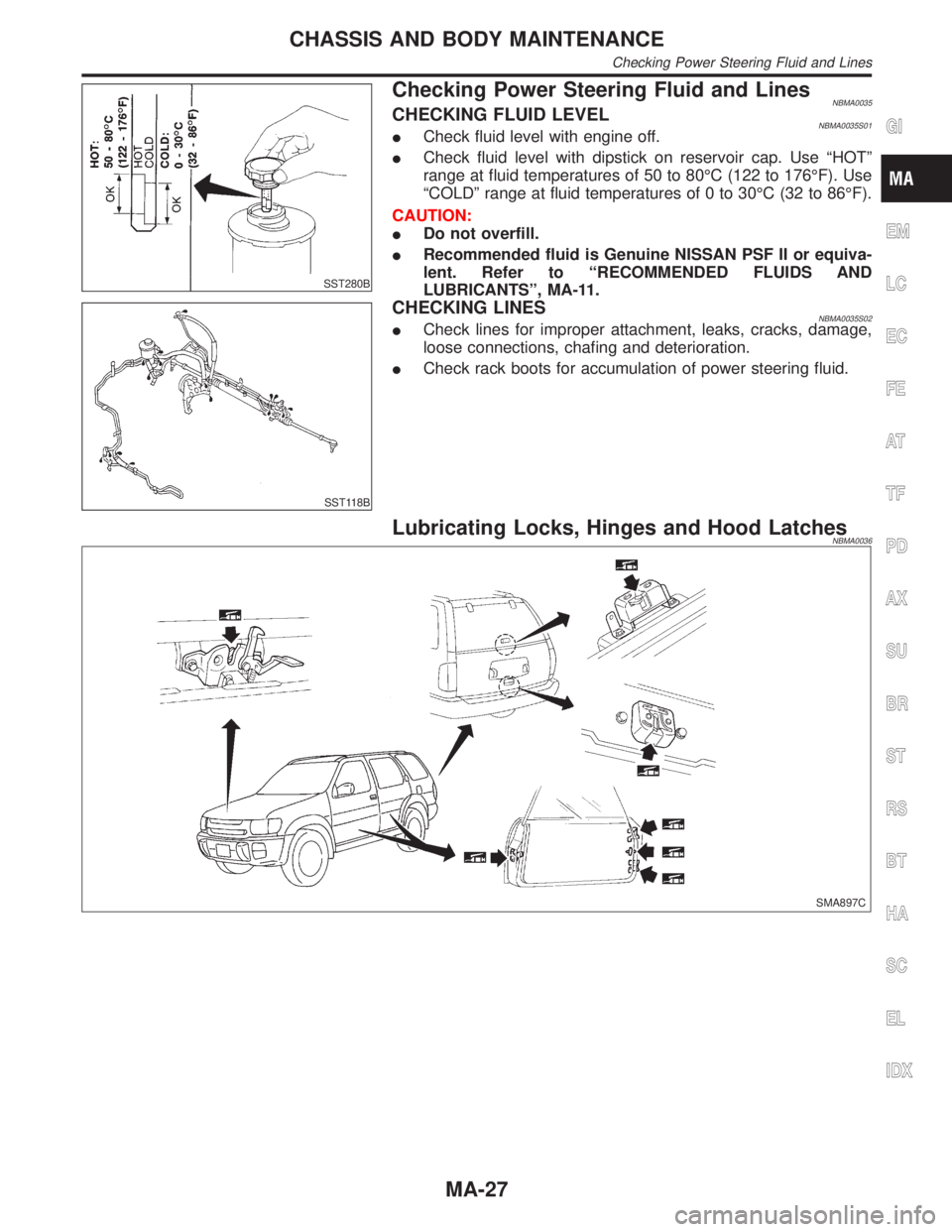
Checking Power Steering Fluid and LinesNBMA0035CHECKING FLUID LEVELNBMA0035S01ICheck fluid level with engine off.
ICheck fluid level with dipstick on reservoir cap. Use ªHOTº
range at fluid temperatures of 50 to 80ÉC (122 to 176ÉF). Use
ªCOLDº range at fluid temperatures of 0 to 30ÉC (32 to 86ÉF).
CAUTION:
IDo not overfill.
IRecommended fluid is Genuine NISSAN PSF II or equiva-
lent. Refer to ªRECOMMENDED FLUIDS AND
LUBRICANTSº, MA-11.
SST118B
CHECKING LINESNBMA0035S02ICheck lines for improper attachment, leaks, cracks, damage,
loose connections, chafing and deterioration.
ICheck rack boots for accumulation of power steering fluid.
Lubricating Locks, Hinges and Hood LatchesNBMA0036
SMA897C
GI
EM
LC
EC
FE
AT
TF
PD
AX
SU
BR
ST
RS
BT
HA
SC
EL
IDX
CHASSIS AND BODY MAINTENANCE
Checking Power Steering Fluid and Lines
MA-27
Page 2182 of 2395
STEERING SYSTEM
SECTION
ST
CONTENTS
PRECAUTIONS...............................................................2
Supplemental Restraint System (SRS)²AIR
BAG²and²SEAT BELT PRE-TENSIONER²...............2
Precautions for Steering System .................................2
PREPARATION...............................................................3
Special Service Tools ..................................................3
Commercial Service Tools ...........................................5
NOISE, VIBRATION AND HARSHNESS (NVH)
TROUBLESHOOTING.....................................................6
NVH Troubleshooting Chart.........................................6
ON-VEHICLE SERVICE..................................................7
Checking Steering Wheel Play ....................................7
Checking Neutral Position on Steering Wheel ............7
PRE-CHECKING........................................................7
CHECKING...............................................................7
Front Wheel Turning Angle ..........................................7
Checking Gear Housing Movement ............................8
Adjusting Rack Retainer ..............................................8
Checking and Adjusting Drive Belts ............................8
Checking Fluid Level ...................................................8
Checking Fluid Leakage ..............................................8
Bleeding Hydraulic System..........................................9
Checking Steering Wheel Turning Force ....................9
Checking Hydraulic System.......................................10
STEERING WHEEL AND STEERING COLUMN......... 11
Components............................................................... 11
Removal and Installation ........................................... 11
STEERING WHEEL................................................. 11
STEERING COLUMN...............................................12
Disassembly and Assembly .......................................13
Inspection...................................................................14
TILT MECHANISM...................................................14
STEERING TRANSFER GEAR.....................................15
Removal .....................................................................15
Installation ..................................................................16
Inspection...................................................................16
POWER STEERING GEAR AND LINKAGE................17
Components...............................................................17
Removal and Installation ...........................................18
Disassembly...............................................................19
Inspection...................................................................20
BOOT.....................................................................20
RACK.....................................................................20
PINION ASSEMBLY.................................................20
GEAR HOUSING CYLINDER....................................20
TIE-ROD OUTER AND INNER SOCKETS..................21
Assembly ...................................................................21
Adjustment .................................................................24
POWER STEERING OIL PUMP....................................27
Components...............................................................27
Pre-disassembly Inspection .......................................27
Disassembly...............................................................28
Inspection...................................................................29
Assembly ...................................................................29
SERVICE DATA AND SPECIFICATIONS (SDS).........32
General Specifications ...............................................32
Steering Wheel ..........................................................32
Steering Column ........................................................32
Steering Transfer Gear ..............................................32
Steering Gear and Linkage .......................................33
Power Steering ..........................................................33
GI
MA
EM
LC
EC
FE
AT
TF
PD
AX
SU
BR
RS
BT
HA
SC
EL
IDX
Page 2190 of 2395
CAUTION:
Do not hold the steering wheel in a locked position for more
than 15 seconds.
4. If fluid leakage at connectors is noticed, loosen flare nut and
then retighten.
Do not overtighten connector as this can damage O-ring,
washer and connector.
5. Check rack boots for accumulation of power steering fluid.
Bleeding Hydraulic SystemNBST00131. Raise front end of vehicle until wheels are clear of the ground.
2. Add fluid into oil tank to specified level. Then, quickly turn
steering wheel fully to right and left and lightly touch steering
stoppers.
Repeat steering wheel operation until fluid level no longer
decreases.
3. Start engine.
Repeat step 2 above.
IIncomplete air bleeding will cause the following to occur. When
this happens, bleed air again.
a) Air bubbles in reservoir tank
b) Clicking noise in oil pump
c) Excessive buzzing in oil pump
Fluid noise may occur in the valve or oil pump. This is common
when the vehicle is stationary or while turning steering wheel
slowly. This does not affect performance or durability of the system.
SST491B
SST090B
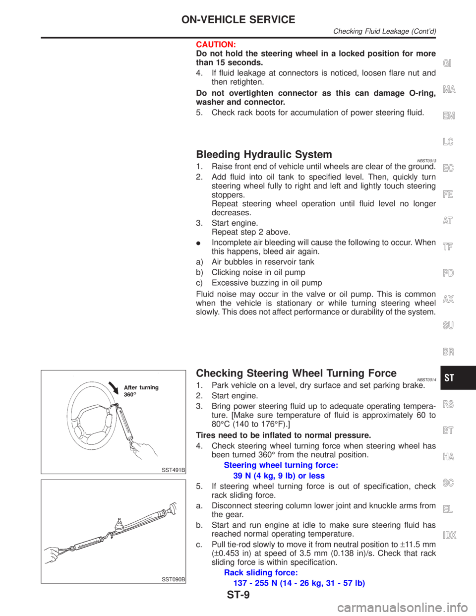
Checking Steering Wheel Turning ForceNBST00141. Park vehicle on a level, dry surface and set parking brake.
2. Start engine.
3. Bring power steering fluid up to adequate operating tempera-
ture. [Make sure temperature of fluid is approximately 60 to
80ÉC (140 to 176ÉF).]
Tires need to be inflated to normal pressure.
4. Check steering wheel turning force when steering wheel has
been turned 360É from the neutral position.
Steering wheel turning force:
39 N (4 kg, 9 lb) or less
5. If steering wheel turning force is out of specification, check
rack sliding force.
a. Disconnect steering column lower joint and knuckle arms from
the gear.
b. Start and run engine at idle to make sure steering fluid has
reached normal operating temperature.
c. Pull tie-rod slowly to move it from neutral position to±11.5 mm
(±0.453 in) at speed of 3.5 mm (0.138 in)/s. Check that rack
sliding force is within specification.
Rack sliding force:
137 - 255 N (14 - 26 kg, 31 - 57 lb)
GI
MA
EM
LC
EC
FE
AT
TF
PD
AX
SU
BR
RS
BT
HA
SC
EL
IDX
ON-VEHICLE SERVICE
Checking Fluid Leakage (Cont'd)
ST-9
Page 2198 of 2395

ComponentsNBST0026
SST618CB
1. Rear cover cap
2. Rear housing assembly
3. Pinion seal ring
4. Pinion assembly
5. O-ring
6. Shim
7. Pinion oil seal
8. Lock nut
9. Adjusting screw
10. Spring11. Retainer
12. Gear housing assembly
13. Rack oil seal
14. Rack assembly
15. Rack seal ring
16. O-ring
17. O-ring
18. Rack bushing
19. Rack oil seal
20. Snap ring21. End cover assembly
22. Boot clamp
23. Dust boot
24. Boot clamp
25. Lock plate
26. Tie-rod inner socket
27. Tie-rod
28. Tie-rod outer socket
29. Cotter pin
30. Cylinder tube
GI
MA
EM
LC
EC
FE
AT
TF
PD
AX
SU
BR
RS
BT
HA
SC
EL
IDX
POWER STEERING GEAR AND LINKAGE
Components
ST-17
Page 2200 of 2395
in high-pressure connector. Take care to install the proper
O-ring.
SST616C
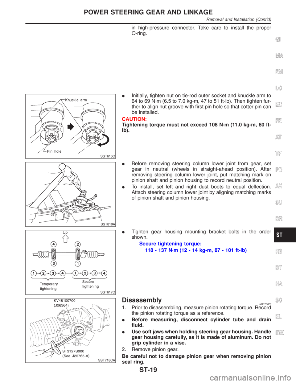
IInitially, tighten nut on tie-rod outer socket and knuckle arm to
64 to 69 N´m (6.5 to 7.0 kg-m, 47 to 51 ft-lb). Then tighten fur-
ther to align nut groove with first pin hole so that cotter pin can
be installed.
CAUTION:
Tightening torque must not exceed 108 N´m (11.0 kg-m, 80 ft-
lb).
SST819A
IBefore removing steering column lower joint from gear, set
gear in neutral (wheels in straight-ahead position). After
removing steering column lower joint, put matching mark on
pinion shaft and pinion housing to record neutral position.
ITo install, set left and right dust boots to equal deflection.
Attach steering column lower joint by aligning matching marks
of pinion shaft and pinion housing.
SST617C
ITighten gear housing mounting bracket bolts in the order
shown.
Secure tightening torque:
118 - 137 N´m (12 - 14 kg-m, 87 - 101 ft-lb)
SST718CA
DisassemblyNBST00281. Prior to disassembling, measure pinion rotating torque. Record
the pinion rotating torque as a reference.
IBefore measuring, disconnect cylinder tube and drain
fluid.
IUse soft jaws when holding steering gear housing. Handle
gear housing carefully, as it is made of aluminum. Do not
grip cylinder in a vise.
2. Remove pinion gear.
Be careful not to damage pinion gear when removing pinion
seal ring.
GI
MA
EM
LC
EC
FE
AT
TF
PD
AX
SU
BR
RS
BT
HA
SC
EL
IDX
POWER STEERING GEAR AND LINKAGE
Removal and Installation (Cont'd)
ST-19
Page 2201 of 2395
SST051C
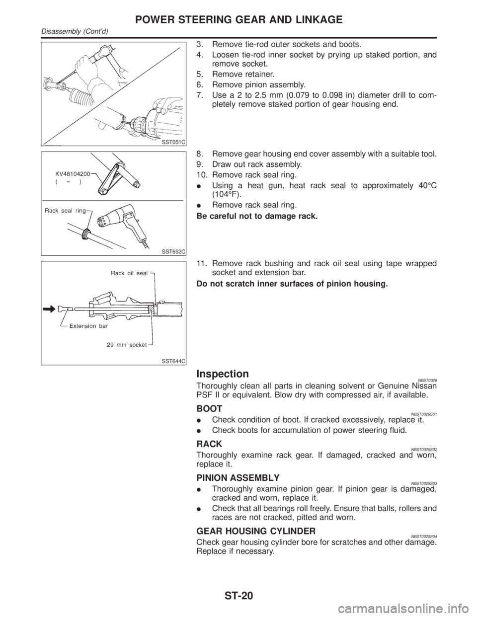
3. Remove tie-rod outer sockets and boots.
4. Loosen tie-rod inner socket by prying up staked portion, and
remove socket.
5. Remove retainer.
6. Remove pinion assembly.
7. Usea2to2.5mm(0.079 to 0.098 in) diameter drill to com-
pletely remove staked portion of gear housing end.
SST652C
8. Remove gear housing end cover assembly with a suitable tool.
9. Draw out rack assembly.
10. Remove rack seal ring.
IUsing a heat gun, heat rack seal to approximately 40ÉC
(104ÉF).
IRemove rack seal ring.
Be careful not to damage rack.
SST644C
11. Remove rack bushing and rack oil seal using tape wrapped
socket and extension bar.
Do not scratch inner surfaces of pinion housing.
InspectionNBST0029Thoroughly clean all parts in cleaning solvent or Genuine Nissan
PSF II or equivalent. Blow dry with compressed air, if available.
BOOTNBST0029S01ICheck condition of boot. If cracked excessively, replace it.
ICheck boots for accumulation of power steering fluid.
RACKNBST0029S02Thoroughly examine rack gear. If damaged, cracked and worn,
replace it.
PINION ASSEMBLYNBST0029S03IThoroughly examine pinion gear. If pinion gear is damaged,
cracked and worn, replace it.
ICheck that all bearings roll freely. Ensure that balls, rollers and
races are not cracked, pitted and worn.
GEAR HOUSING CYLINDERNBST0029S04Check gear housing cylinder bore for scratches and other damage.
Replace if necessary.
POWER STEERING GEAR AND LINKAGE
Disassembly (Cont'd)
ST-20
Page 2205 of 2395
SST609C
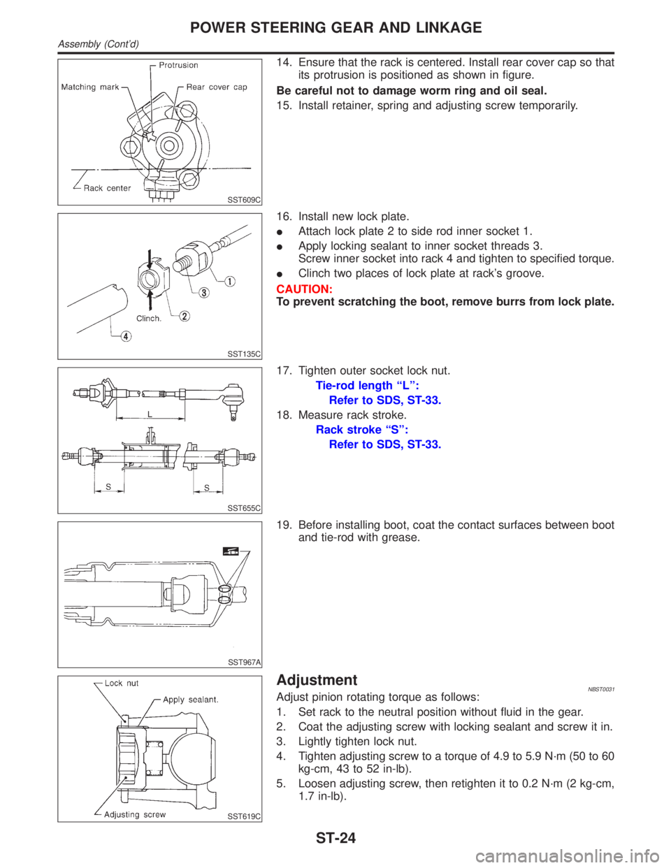
14. Ensure that the rack is centered. Install rear cover cap so that
its protrusion is positioned as shown in figure.
Be careful not to damage worm ring and oil seal.
15. Install retainer, spring and adjusting screw temporarily.
SST135C
16. Install new lock plate.
IAttach lock plate 2 to side rod inner socket 1.
IApply locking sealant to inner socket threads 3.
Screw inner socket into rack 4 and tighten to specified torque.
IClinch two places of lock plate at rack's groove.
CAUTION:
To prevent scratching the boot, remove burrs from lock plate.
SST655C
17. Tighten outer socket lock nut.
Tie-rod length ªLº:
Refer to SDS, ST-33.
18. Measure rack stroke.
Rack stroke ªSº:
Refer to SDS, ST-33.
SST967A
19. Before installing boot, coat the contact surfaces between boot
and tie-rod with grease.
SST619C
AdjustmentNBST0031Adjust pinion rotating torque as follows:
1. Set rack to the neutral position without fluid in the gear.
2. Coat the adjusting screw with locking sealant and screw it in.
3. Lightly tighten lock nut.
4. Tighten adjusting screw to a torque of 4.9 to 5.9 N´m (50 to 60
kg-cm, 43 to 52 in-lb).
5. Loosen adjusting screw, then retighten it to 0.2 N´m (2 kg-cm,
1.7 in-lb).
POWER STEERING GEAR AND LINKAGE
Assembly (Cont'd)
ST-24