2001 INFINITI QX4 Vacuum cut
[x] Cancel search: Vacuum cutPage 894 of 2395

7 CHECK FOR EVAP LEAK
Without CONSULT-II
1. Turn ignition switch ªOFFº.
2. Apply 12 volts DC to EVAP canister vent control valve. The valve will close. (Continue to apply 12 volts until the end of
test.)
SEF598U
3. Apply 12 volts DC to vacuum cut valve bypass valve. The valve will open. (Continue to apply 12V until the end of test.)
SEF599U
4. Pressurize the EVAP line using pressure pump with 1.3 to 2.7 kPa (10 to 20 mmHg, 0.39 to 0.79 inHg), then remove
pump and EVAP service port adapter.
NOTE:
INever use compressed air or a high pressure pump.
IDo not exceed 4.12 kPa (0.042 kg/cm
2, 0.6 psi) of pressure in the system.
5. Using EVAP leak detector, locate the EVAP leak. For the leak detector, refer to the instruction manual for more details.
Refer to ªEVAPORATIVE EMISSION LINE DRAWINGº, EC-36.
SEF200U
OK or NG
OK©GO TO 8.
NG©Repair or replace.
GI
MA
EM
LC
FE
AT
TF
PD
AX
SU
BR
ST
RS
BT
HA
SC
EL
IDX
DTC P0440 EVAP CONTROL SYSTEM (SMALL LEAK) (NEGATIVE PRESSURE)
Diagnostic Procedure (Cont'd)
EC-359
Page 936 of 2395

10 CHECK FOR EVAP LEAK
Without CONSULT-II
1. Turn ignition switch ªOFFº.
2. Apply 12 volts DC to EVAP canister vent control valve. The valve will close. (Continue to apply 12 volts until the end of
test.)
SEF598U
3. Apply 12 volts DC to vacuum cut valve bypass valve. The valve will open. (Continue to apply 12V until the end of test.)
SEF599U
4. Pressurize the EVAP line using pressure pump with 1.3 to 2.7 kPa (10 to 20 mmHg, 0.39 to 0.79 inHg), then remove
pump and EVAP service port adapter.
NOTE:
INever use compressed air or a high pressure pump.
IDo not exceed 4.12 kPa (0.042 kg/cm
2, 0.6 psi) of pressure in the system.
5. Using EVAP leak detector, locate the EVAP leak. For the leak detector, refer to the instruction manual for more details.
Refer to ªEVAPORATIVE EMISSION LINE DRAWINGº, EC-36.
SEF200U
OK or NG
OK©GO TO 12.
NG©Repair or replace.
GI
MA
EM
LC
FE
AT
TF
PD
AX
SU
BR
ST
RS
BT
HA
SC
EL
IDX
DTC P0455 EVAP CONTROL SYSTEM (GROSS LEAK)
Diagnostic Procedure (Cont'd)
EC-401
Page 994 of 2395

SEF002Z
COMPONENT DESCRIPTIONNBEC0523S02Swirl Control Valve Control Solenoid ValveNBEC0523S0201The swirl control valve control solenoid valve responds to signals
from the ECM. When the ECM sends an ON (ground) signal, the
solenoid valve is bypassed to apply intake manifold vacuum to the
swirl control valve actuator. This operation closes the swirl control
valve. When the ECM sends an OFF signal, the vacuum signal is
cut and the swirl control valve opens.
CONSULT-II Reference Value in Data Monitor
Mode
NBEC0524Specification data are reference values.
MONITOR ITEM CONDITION SPECIFICATION
SWRL CONT S/VIEngine speed: IdleEngine coolant temperature is
between 15ÉC (59ÉF) to 50ÉC
(122ÉF).ON
Engine coolant temperature is
above 55ÉC (131ÉF).OFF
ECM Terminals and Reference ValueNBEC0673Specification data are reference values and are measured between each terminal and ground.
CAUTION:
Do not use ECM ground terminals when measuring input/output voltage. Doing so may result in dam-
age to the ECM's transistor. Use a ground other than ECM terminals, such as the ground.
TERMI-
NAL
NO.WIRE
COLORITEM CONDITION DATA (DC Voltage)
29 GSwirl control valve con-
trol solenoid valve[Engine is running]
IIdle speed
IEngine coolant temperature is between 15 to
50ÉC (59 to 122ÉF).0 - 1.0V
[Engine is running]
IIdle speed
IEngine coolant temperature is above 55ÉC
(131ÉF).BATTERY VOLTAGE
(11 - 14V)
On Board Diagnosis LogicNBEC0526Malfunction is detected when
(Malfunction A)An improper voltage signal is sent to ECM through
swirl control valve control solenoid valve,
(Malfunction B)The vacuum signal is not sent to swirl control
valve under specified driving conditions, even though swirl control
valve control solenoid valve is ON,
(Malfunction C)The vacuum signal is sent to swirl control valve
even though swirl control valve control solenoid valve is OFF.
GI
MA
EM
LC
FE
AT
TF
PD
AX
SU
BR
ST
RS
BT
HA
SC
EL
IDX
DTC P1130 SWIRL CONTROL VALVE CONTROL SOLENOID VALVE
Description (Cont'd)
EC-459
Page 1063 of 2395
place or refilling/draining fuel until the output voltage condition
of the ªFUEL LEVEL SEº meets within the range above and
leave the vehicle for more than 1 hour. Then start from step 1).
3) Turn ignition switch ªOFFº and wait at least 5 seconds.
4) Turn ignition switch ªONº.
5) Select ªEVAP VERY/SML LEAK P1441º of ªEVAPORATIVE
SYSTEMº in ªDTC WORK SUPPORTº mode with CONSULT-
II.
Follow the instruction displayed.
6) Make sure that ªOKº is displayed.
If ªNGº is displayed, refer to ªDiagnostic Procedureº, EC-529.
NOTE:
IIf the engine speed cannot be maintained within the range
displayed on CONSULT-II screen, go to ªBasic
inspectionº, EC-101.
IMake sure that EVAP hoses are connected to EVAP canis-
ter purge volume control solenoid valve properly.
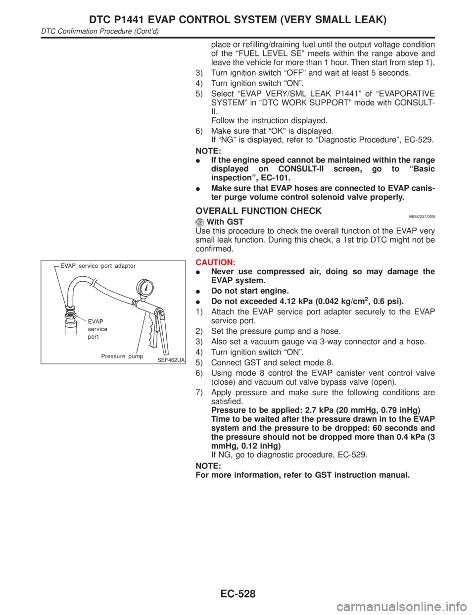
OVERALL FUNCTION CHECKNBEC0317S05With GST
Use this procedure to check the overall function of the EVAP very
small leak function. During this check, a 1st trip DTC might not be
confirmed.
SEF462UA
CAUTION:
INever use compressed air, doing so may damage the
EVAP system.
IDo not start engine.
IDo not exceeded 4.12 kPa (0.042 kg/cm
2, 0.6 psi).
1) Attach the EVAP service port adapter securely to the EVAP
service port.
2) Set the pressure pump and a hose.
3) Also set a vacuum gauge via 3-way connector and a hose.
4) Turn ignition switch ªONº.
5) Connect GST and select mode 8.
6) Using mode 8 control the EVAP canister vent control valve
(close) and vacuum cut valve bypass valve (open).
7) Apply pressure and make sure the following conditions are
satisfied.
Pressure to be applied: 2.7 kPa (20 mmHg, 0.79 inHg)
Time to be waited after the pressure drawn in to the EVAP
system and the pressure to be dropped: 60 seconds and
the pressure should not be dropped more than 0.4 kPa (3
mmHg, 0.12 inHg)
If NG, go to diagnostic procedure, EC-529.
NOTE:
For more information, refer to GST instruction manual.
DTC P1441 EVAP CONTROL SYSTEM (VERY SMALL LEAK)
DTC Confirmation Procedure (Cont'd)
EC-528
Page 1068 of 2395
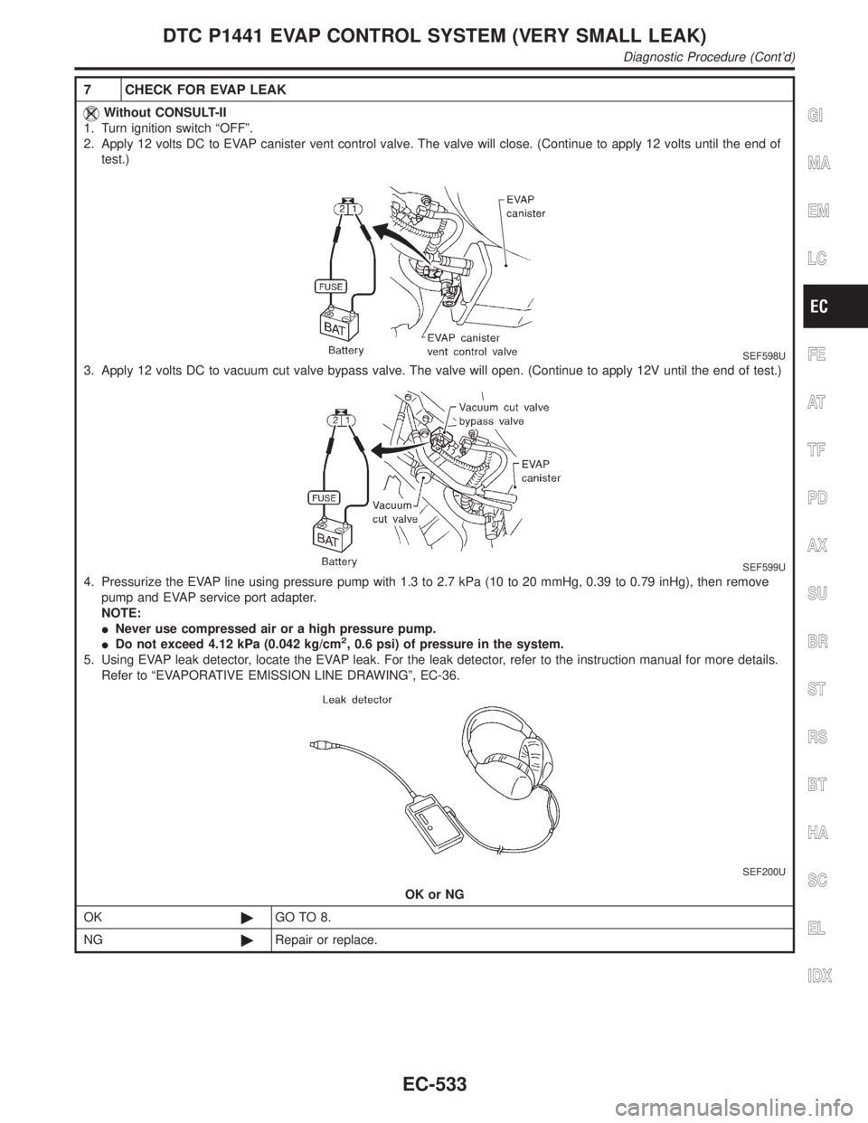
7 CHECK FOR EVAP LEAK
Without CONSULT-II
1. Turn ignition switch ªOFFº.
2. Apply 12 volts DC to EVAP canister vent control valve. The valve will close. (Continue to apply 12 volts until the end of
test.)
SEF598U
3. Apply 12 volts DC to vacuum cut valve bypass valve. The valve will open. (Continue to apply 12V until the end of test.)
SEF599U
4. Pressurize the EVAP line using pressure pump with 1.3 to 2.7 kPa (10 to 20 mmHg, 0.39 to 0.79 inHg), then remove
pump and EVAP service port adapter.
NOTE:
INever use compressed air or a high pressure pump.
IDo not exceed 4.12 kPa (0.042 kg/cm
2, 0.6 psi) of pressure in the system.
5. Using EVAP leak detector, locate the EVAP leak. For the leak detector, refer to the instruction manual for more details.
Refer to ªEVAPORATIVE EMISSION LINE DRAWINGº, EC-36.
SEF200U
OK or NG
OK©GO TO 8.
NG©Repair or replace.
GI
MA
EM
LC
FE
AT
TF
PD
AX
SU
BR
ST
RS
BT
HA
SC
EL
IDX
DTC P1441 EVAP CONTROL SYSTEM (VERY SMALL LEAK)
Diagnostic Procedure (Cont'd)
EC-533
Page 1109 of 2395
Possible CauseNBEC0591IEVAP canister vent control valve
IEVAP control system pressure sensor and circuit
IBlocked rubber tube to EVAP canister vent control valve
IWater separator
IEVAP canister is saturated with water.
IVacuum cut valve
DTC Confirmation ProcedureNBEC0342NOTE:
IIf DTC P1448 is displayed with P0440 or P1440, perform
trouble diagnosis for DTC P1448 first.
IIf ªDTC Confirmation Procedureº has been previously
conducted, always turn ignition switch ªOFFº and wait at least
10 seconds before conducting the next test.
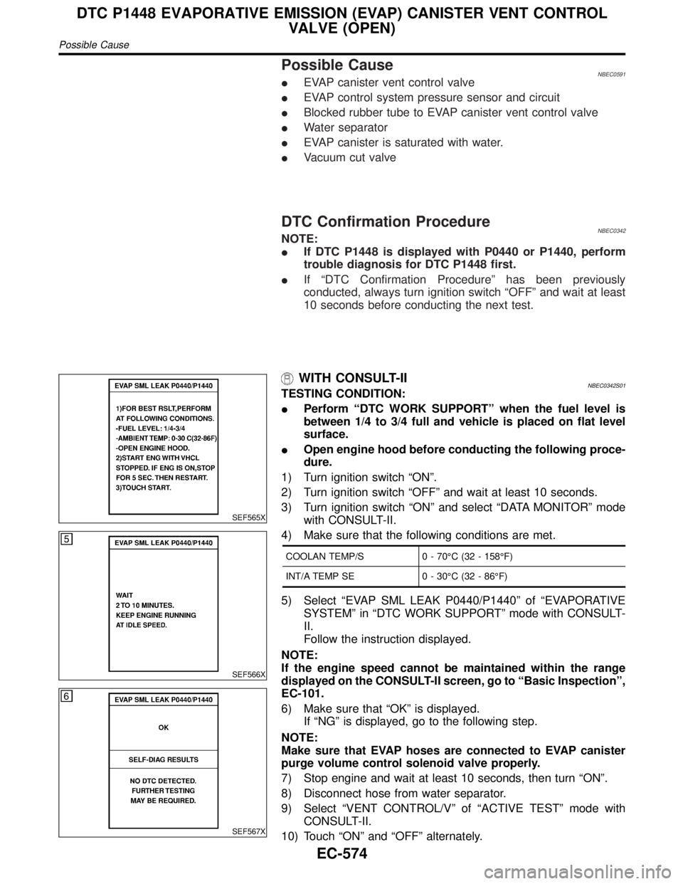
SEF565X
SEF566X
SEF567X
WITH CONSULT-IINBEC0342S01TESTING CONDITION:
IPerform ªDTC WORK SUPPORTº when the fuel level is
between 1/4 to 3/4 full and vehicle is placed on flat level
surface.
IOpen engine hood before conducting the following proce-
dure.
1) Turn ignition switch ªONº.
2) Turn ignition switch ªOFFº and wait at least 10 seconds.
3) Turn ignition switch ªONº and select ªDATA MONITORº mode
with CONSULT-II.
4) Make sure that the following conditions are met.
COOLAN TEMP/S 0 - 70ÉC (32 - 158ÉF)
INT/A TEMP SE 0 - 30ÉC (32 - 86ÉF)
5) Select ªEVAP SML LEAK P0440/P1440º of ªEVAPORATIVE
SYSTEMº in ªDTC WORK SUPPORTº mode with CONSULT-
II.
Follow the instruction displayed.
NOTE:
If the engine speed cannot be maintained within the range
displayed on the CONSULT-II screen, go to ªBasic Inspectionº,
EC-101.
6) Make sure that ªOKº is displayed.
If ªNGº is displayed, go to the following step.
NOTE:
Make sure that EVAP hoses are connected to EVAP canister
purge volume control solenoid valve properly.
7) Stop engine and wait at least 10 seconds, then turn ªONº.
8) Disconnect hose from water separator.
9) Select ªVENT CONTROL/Vº of ªACTIVE TESTº mode with
CONSULT-II.
10) Touch ªONº and ªOFFº alternately.
DTC P1448 EVAPORATIVE EMISSION (EVAP) CANISTER VENT CONTROL
VALVE (OPEN)
Possible Cause
EC-574
Page 1114 of 2395
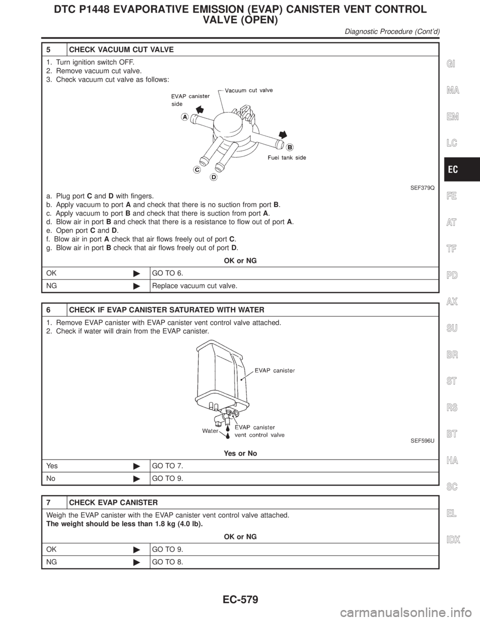
5 CHECK VACUUM CUT VALVE
1. Turn ignition switch OFF.
2. Remove vacuum cut valve.
3. Check vacuum cut valve as follows:
SEF379Q
a. Plug portCandDwith fingers.
b. Apply vacuum to portAand check that there is no suction from portB.
c. Apply vacuum to portBand check that there is suction from portA.
d. Blow air in portBand check that there is a resistance to flow out of portA.
e. Open portCandD.
f. Blow air in portAcheck that air flows freely out of portC.
g. Blow air in portBcheck that air flows freely out of portD.
OK or NG
OK©GO TO 6.
NG©Replace vacuum cut valve.
6 CHECK IF EVAP CANISTER SATURATED WITH WATER
1. Remove EVAP canister with EVAP canister vent control valve attached.
2. Check if water will drain from the EVAP canister.
SEF596U
YesorNo
Ye s©GO TO 7.
No©GO TO 9.
7 CHECK EVAP CANISTER
Weigh the EVAP canister with the EVAP canister vent control valve attached.
The weight should be less than 1.8 kg (4.0 lb).
OK or NG
OK©GO TO 9.
NG©GO TO 8.
GI
MA
EM
LC
FE
AT
TF
PD
AX
SU
BR
ST
RS
BT
HA
SC
EL
IDX
DTC P1448 EVAPORATIVE EMISSION (EVAP) CANISTER VENT CONTROL
VALVE (OPEN)
Diagnostic Procedure (Cont'd)
EC-579
Page 1120 of 2395
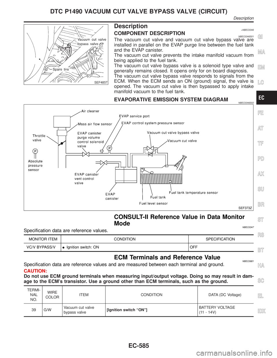
SEF485T
Description=NBEC0346COMPONENT DESCRIPTIONNBEC0346S01The vacuum cut valve and vacuum cut valve bypass valve are
installed in parallel on the EVAP purge line between the fuel tank
and the EVAP canister.
The vacuum cut valve prevents the intake manifold vacuum from
being applied to the fuel tank.
The vacuum cut valve bypass valve is a solenoid type valve and
generally remains closed. It opens only for on board diagnosis.
The vacuum cut valve bypass valve responds to signals from the
ECM. When the ECM sends an ON (ground) signal, the valve is
opened. The vacuum cut valve is then bypassed to apply intake
manifold vacuum to the fuel tank.
EVAPORATIVE EMISSION SYSTEM DIAGRAMNBEC0346S02
SEF373Z
CONSULT-II Reference Value in Data Monitor
Mode
NBEC0347Specification data are reference values.
MONITOR ITEM CONDITION SPECIFICATION
VC/V BYPASS/VIIgnition switch: ON OFF
ECM Terminals and Reference ValueNBEC0681Specification data are reference values and are measured between each terminal and ground.
CAUTION:
Do not use ECM ground terminals when measuring input/output voltage. Doing so may result in dam-
age to the ECM's transistor. Use a ground other than ECM terminals, such as the ground.
TERMI-
NAL
NO.WIRE
COLORITEM CONDITION DATA (DC Voltage)
39 G/WVacuum cut valve
bypass valve[Ignition switch ªONº]BATTERY VOLTAGE
(11 - 14V)
GI
MA
EM
LC
FE
AT
TF
PD
AX
SU
BR
ST
RS
BT
HA
SC
EL
IDX
DTC P1490 VACUUM CUT VALVE BYPASS VALVE (CIRCUIT)
Description
EC-585