2001 INFINITI QX4 Battery replace
[x] Cancel search: Battery replacePage 457 of 2395

Control Unit
DIAGNOSTIC PROCEDURE=NBBR0106Malfunction code No. 71
1 INSPECTION START
ABS actuator and electric unit power supply and ground circuit inspection
SBR497E
©GO TO 2.
2 CHECK CONNECTOR
1. Disconnect ABS actuator and electric unit connector.
Check terminals for damage or loose connection. Then reconnect connector.
2. Carry out self-diagnosis again.
Does warning lamp activate again?
Ye s©GO TO 3.
No©INSPECTION END
3 CHECK ABS ACTUATOR AND ELECTRIC UNIT POWER SUPPLY CIRCUIT
Check voltage. Refer to ª5. CHECK ABS ACTUATOR AND ELECTRIC UNIT POWER SUPPLY CIRCUITº in ªDIAGNOS-
TIC PROCEDUREº, ªLow Voltageº, BR-63.
Does battery voltage exist when ignition switch is turned ON?
Ye s©GO TO 4.
No©Repair.
4 CHECK WARNING LAMP INDICATION
Does warning lamp indicate code No. 71 again?
YesorNo
Ye s©Replace ABS actuator and electric unit.
No©Inspect the system according to the code No.
TROUBLE DIAGNOSES FOR SELF-DIAGNOSTIC ITEMSABS
Control Unit
BR-68
Page 464 of 2395

5 CHECK ABS ACTUATOR AND ELECTRIC UNIT POWER SUPPLY CIRCUIT
1. Disconnect ABS actuator and electric unit connector.
2. Check voltage between ABS actuator and electric unit connector E111 (body side) terminal 15 and ground.
SBR495E
Does battery voltage exist when ignition switch is turned ON?
Ye s©GO TO 6.
No©Check the following.
If NG, repair harness or connector.
IHarness connector E111
IHarness for open or short between ABS actuator and electric unit and fuse
6 CHECK WARNING LAMP
1. Disconnect ABS actuator and electric unit connector.
2. Connect suitable wire between ABS actuator and electric unit connector E111 (body side) terminal 10 (2WD) or 21
(4WD) and ground.
SBR502E
Does the warning lamp deactivate?
Ye s©Replace ABS actuator and electric unit.
No©GO TO 7.
GI
MA
EM
LC
EC
FE
AT
TF
PD
AX
SU
ST
RS
BT
HA
SC
EL
IDX
TROUBLE DIAGNOSES FOR SYMPTOMSABS
7. Warning Lamp Stays On When Ignition Switch Is Turned On (Cont'd)
BR-75
Page 465 of 2395

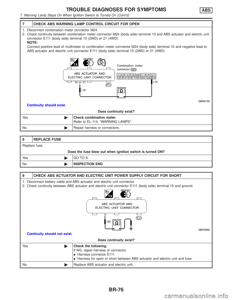
7 CHECK ABS WARNING LAMP CONTROL CIRCUIT FOR OPEN
1. Disconnect combination meter connector M24.
2. Check continuity between combination meter connector M24 (body side) terminal 10 and ABS actuator and electric unit
connector E111 (body side) terminal 10 (2WD) or 21 (4WD).
NOTE:
Connect positive lead of multimeter to combination meter connector M24 (body side) terminal 10 and negative lead to
ABS actuator and electric unit connector E111 (body side) terminal 10 (2WD) or 21 (4WD).
SBR675E
Continuity should exist.
Does continuity exist?
Ye s©Check combination meter.
Refer to EL-114, ªWARNING LAMPSº.
No©Repair harness or connectors.
8 REPLACE FUSE
Replace fuse.
Does the fuse blow out when ignition switch is turned ON?
Ye s©GO TO 9.
No©INSPECTION END
9 CHECK ABS ACTUATOR AND ELECTRIC UNIT POWER SUPPLY CIRCUIT FOR SHORT
1. Disconnect battery cable and ABS actuator and electric unit connector.
2. Check continuity between ABS actuator and electric unit connector E111 (body side) terminal 15 and ground.
SBR496E
Continuity should not exist.
Does continuity exist?
Ye s©Check the following.
If NG, repair harness or connector.
IHarness connector E111
IHarness for open or short between ABS actuator and electric unit and fuse
No©Replace ABS actuator and electric unit.
TROUBLE DIAGNOSES FOR SYMPTOMSABS
7. Warning Lamp Stays On When Ignition Switch Is Turned On (Cont'd)
BR-76
Page 588 of 2395

25 CHECK HEATED OXYGEN SENSOR 1 (FRONT) (BANK 1) SIGNAL
With CONSULT-II
1. Stop engine.
2. Replace heated oxygen sensor 1 (front) (bank 1).
3. Start engine and warm it up to normal operating temperature.
4. Run engine at approx. 2,000 rpm for approx. 2 minutes under no-load.
5. See ªHO2S1 MNTR (B1)º in ªDATA MONITORº mode.
6. Maintaining engine at 2,000 rpm under no-load (engine is warmed up to normal operating temperature.), check that the
monitor fluctuates between ªLEANº and ªRICHº more than 5 times during 10 seconds.
1 time: RICH®LEAN®RICH
2 times: RICH®LEAN®RICH®LEAN®RICH
Without CONSULT-II
1. Stop engine.
2. Replace heated oxygen sensor 1 (front) (bank 1).
3. Start engine and warm it up to normal operating temperature.
4. Run engine at approx. 2,000 rpm for approx. 2 minutes under no-load.
5. Set voltmeter probe between ECM terminal 63 and ground.
6. Make sure that the voltage fluctuates between 0 - 0.3V and 0.6 - 1.0V more than 5 times during 10 seconds at 2,000
rpm.
1 time: 0 - 0.3V®0.6 - 1.0V®0 - 0.3V
2 times: 0 - 0.3V®0.6 - 1.0V®0 - 0.3V®0.6 - 1.0V®0 - 0.3V
OK or NG
OK©INSPECTION END
NG©GO TO 26.
26 DETECT MALFUNCTIONING PART
Check the following.
ICheck fuel pressure regulator. Refer to EC-40.
ICheck mass air flow sensor and its circuit. Refer to EC-150.
ICheck injector and its circuit. Refer to EC-616.
Clean or replace if necessary.
ICheck engine coolant temperature sensor and its circuit. Refer to EC-187.
ICheck ECM function by substituting another known-good ECM.
(ECM may be the cause of a problem, but this is rarely the case.)
©GO TO 3.
27 CHECK HEATED OXYGEN SENSOR 1 (FRONT) (BANK 1) HARNESS
1. Turn off engine and disconnect battery ground cable.
2. Disconnect ECM harness connector.
3. Disconnect heated oxygen sensor 1 (front) (bank 1) harness connector.
4. Check harness continuity between ECM terminal 63 and heated oxygen sensor 1 (front) RH harness connector terminal
1.
Refer to Wiring Diagram, EC-196.
Continuity should exist.
OK or NG
OK©GO TO 30.
NG©GO TO 29.
GI
MA
EM
LC
FE
AT
TF
PD
AX
SU
BR
ST
RS
BT
HA
SC
EL
IDX
BASIC SERVICE PROCEDURE
Idle Speed/Ignition Timing/Idle Mixture Ratio Adjustment (Cont'd)
EC-53
Page 589 of 2395

28 CHECK HEATED OXYGEN SENSOR 1 (FRONT) (BANK 2) HARNESS
1. Turn off engine and disconnect battery ground cable.
2. Disconnect ECM harness connector.
3. Disconnect heated oxygen sensor 1 (front) (bank 2) harness connector.
4. Check harness continuity between ECM terminal 62 and front heated oxygen sensor LH harness connector terminal 1.
Refer to Wiring Diagram, EC-197.
Continuity should exist.
OK or NG
OK©GO TO 30.
NG©GO TO 29.
29 REPAIR OR REPLACE
Repair or replace harness between ECM and heated oxygen sensor 1 (front).
©GO TO 3.
30 PREPARATION FOR ªCOº % CHECK
With CONSULT-II
1. Reconnect ECM harness connector.
2. Turn ignition switch ªONº.
3. Select ªENG COOLANT TEMPº in ªACTIVE TESTº mode.
4. Set ªENG COOLANT TEMPº to 5ÉC (41ÉF) by touching ªDOWNº and ªQdº.
SEF172Y
Without CONSULT-II
1. Disconnect ECM harness connector.
2. Disconnect engine coolant temperature sensor harness connector.
3. Connect a resistor (4.4 kW) between terminals of engine coolant temperature sensor harness connector.
SEF982UA
©GO TO 31.
BASIC SERVICE PROCEDURE
Idle Speed/Ignition Timing/Idle Mixture Ratio Adjustment (Cont'd)
EC-54
Page 592 of 2395

SEF452Y
Idle Air Volume LearningNBEC0642
SEF454Y
SEF455Y
DESCRIPTIONNBEC0642S01ªIdle Air Volume Learningº is an operation to learn the idle air vol-
ume that keeps each engine within the specific range. It must be
performed under any of the following conditions:
IEach time IACV-AAC valve, throttle body or ECM is replaced.
IIdle speed or ignition timing is out of specification.
PRE-CONDITIONINGNBEC0642S02Before performing ªIdle Air Volume Learningº, make sure that all of
the following conditions are satisfied.
Learning will be cancelled if any of the following conditions are
missed for even a moment.
IBattery voltage: More than 12.9V (At idle)
IEngine coolant temperature: 70 - 99ÉC (158 - 210ÉF)
IPNP switch: ON
IElectric load switch: OFF
(Air conditioner, headlamp, rear window defogger)
On vehicles equipped with daytime running light systems, if
the parking brake is applied before the engine is started the
headlamp will not illuminate.
ICooling fan motor: Not operating
ISteering wheel: Neutral (Straight-ahead position)
IVehicle speed: Stopped
ITransmission: Warmed-up
For A/T models with CONSULT-II, drive vehicle until ªFLUID
TEMP SEº in ªDATA MONITORº mode of ªA/Tº system indi-
cates less than 0.9V.
For A/T models without CONSULT-II, drive vehicle for 10 min-
utes.
OPERATION PROCEDURENBEC0642S03With CONSULT-IINBEC0642S03011. Turn ignition switch ªONº and wait at least 1 second.
2. Turn ignition switch ªOFFº and wait at least 10 seconds.
3. Start engine and warm it up to normal operating temperature.
4. Check that all items listed under the topic ªPRE-CONDITION-
INGº (previously mentioned) are in good order.
5. Turn ignition switch ªOFFº and wait at least 10 seconds.
6. Start the engine and let it idle for at least 30 seconds.
7. Select ªIDLE AIR VOL LEARNº in ªWORK SUPPORTº mode.
8. Touch ªSTARTº and wait 20 seconds.
9. Make sure that ªCMPLTº is displayed on CONSULT-II screen.
If ªINCMPº is displayed, ªIdle Air Volume Learningº will not be
carried out successfully. In this case, find the cause of the
problem by referring to the NOTE below.
10. Rev up the engine two or three times. Make sure that idle
speed and ignition timing are within specifications.
ITEM SPECIFICATION
Idle speed 750±50 rpm (in ªPº or ªNº position)
Ignition timing 15ɱ5É BTDC (in ªPº or ªNº position)
GI
MA
EM
LC
FE
AT
TF
PD
AX
SU
BR
ST
RS
BT
HA
SC
EL
IDX
BASIC SERVICE PROCEDURE
Idle Air Volume Learning
EC-57
Page 1188 of 2395

Schematic ................................................................255
Wiring Diagram - D/LOCK -.....................................256
Trouble Diagnoses...................................................261
MULTI-REMOTE CONTROL SYSTEM.......................270
Component Parts and Harness Connector
Location ...................................................................270
System Description ..................................................270
Schematic ................................................................273
Wiring Diagram - MULTI - .......................................274
Trouble Diagnoses...................................................277
ID Code Entry Procedure ........................................289
Remote Controller Battery Replacement.................293
THEFT WARNING SYSTEM.......................................294
Component Parts and Harness Connector
Location ...................................................................294
System Description ..................................................295
Schematic ................................................................298
Wiring Diagram - THEFT -.......................................300
Trouble Diagnoses...................................................306
SMART ENTRANCE CONTROL UNIT.......................319
Description ...............................................................319
Schematic ................................................................322
Smart Entrance Control Unit Inspection Table ........324
INTEGRATED HOMELINK TRANSMITTER...............325
Wiring Diagram - TRNSMT - ...................................325
Trouble Diagnoses...................................................326
IVIS (INFINITI VEHICLE IMMOBILIZER SYSTEM -
NATS)...........................................................................328
Component Parts and Harness Connetor
Location ...................................................................328
System Description ..................................................329
System Composition ................................................329
Wiring Diagram - NATS -.........................................330
CONSULT-II .............................................................331
Trouble Diagnoses...................................................334
How to Replace IVIS (NATS) IMMU .......................347
INFINITI COMMUNICATOR (IVCS)............................348
Precaution ................................................................348
Communicator Response Center Telephone
Number for Technicians ...........................................348
Component Parts and Harness Connector
Location ...................................................................349System Description ..................................................350
Schematic ................................................................358
Wiring Diagram - IVCS -..........................................359
CONSULT-II .............................................................363
Trouble Diagnoses...................................................368
Trouble Diagnoses for Intermittent Incident ............377
Demonstration Mode ...............................................379
System Setting (When IVCS Unit is Replaced) ......381
NAVIGATION SYSTEM...............................................385
Component Parts Location ......................................385
System Description ..................................................386
Schematic ................................................................393
Wiring Diagram - NAVI - ..........................................394
Self-diagnosis Mode ................................................397
Confirmation/Adjustment Mode ...............................400
Setting Mode............................................................410
Trouble diagnoses ...................................................417
This Condition is Not Abnormal ...............................423
Program Loading .....................................................432
Initialization ..............................................................433
ELECTRICAL UNITS LOCATION...............................436
Engine Compartment ...............................................436
Passenger Compartment .........................................438
HARNESS LAYOUT....................................................440
How to Read Harness Layout .................................440
Outline......................................................................441
Main Harness...........................................................442
Engine Room Harness ............................................444
Engine Control Harness ..........................................446
Body Harness LH ....................................................448
Body Harness RH ....................................................449
Back Door Harness .................................................450
Engine and Transmission Harness..........................451
Room Lamp Harness...............................................452
Air Bag Harness ......................................................453
Front Door Harness .................................................454
Rear Door Harness..................................................455
BULB SPECIFICATIONS............................................456
Headlamp.................................................................456
Exterior Lamp ..........................................................456
Interior Lamp............................................................456
WIRING DIAGRAM CODES (CELL CODES).............457GI
MA
EM
LC
EC
FE
AT
TF
PD
AX
SU
BR
ST
RS
BT
HA
SC
IDX
CONTENTS(Cont'd)
EL-3
Page 1226 of 2395

Symptom Possible cause Repair order
LH low beam does not operate, but
LH high beam operates.1. 20A fuse
2. Headlamp LH relay
3. Open in the LH low beam circuit
4. LH low beam ground circuit
5. Xenon bulb
6. HID control unit
7. Booster1. Check 20A fuse (No. 32, located in fusible link and
fuse box). Verify battery positive voltage is present
at terminal 6 of headlamp LH relay.
2. Check headlamp LH relay
3. Check harness between headlamp LH relay terminal
7 and headlamp LH for open circuit.
4. Check harness between headlamp LH and ground.
5. Replace the xenon bulb with other side bulb or new
one. (If headlamps illuminate correctly, replace the
bulb.)
6. Replace the HID control unit with other side control
unit or new one. (If headlamps illuminate correctly,
replace the control unit.)
7. Replace booster as a headlamp assembly.
RH high beam does not operate,
but RH low beam operates.1. Bulb
2. Headlamp RH relay
3. Open in the RH high beams
circuit
4. Lighting switch1. Check bulb.
2. Check headlamp RH relay.
3. Check the following.
a. Harness between headlamp RH relay terminal 5 and
headlamp RH for open circuit
b. Harness between headlamp RH and lighting switch
for open circuit
4. Check lighting switch.
RH low beam does not operate,
but RH high beam operates.1. 20A fuse
2. Headlamp RH relay
3. Open in the RH low beam cir-
cuit
4. RH low beam ground circuit
5. Xenon bulb
6. HID control unit
7. Booster1. Check 20A fuse (No. 31 located in fusible link and
fuse box). Verify battery positive voltage is present
at terminal 6 of headlamp RH relay.
2. Check headlamp RH relay
3. Check harness between headlamp RH relay termi-
nal 7 and headlamp RH for open circuit.
4. Check harness between headlamp RH and ground.
5. Replace the xenon bulb with other side bulb or new
one. (If headlamps illuminate correctly, replace the
bulb.)
6. Replace the HID control unit with other side control
unit or new one. (If headlamps illuminate correctly,
replace the control unit.)
7. Replace booster as a headlamp assembly.
High beam indicator does not work. 1. Bulb
2. Open in high beam circuit1. Check bulb in combination meter.
2. Check the following.
a. Harness between headlamp LH relay and combina-
tion meter for an open circuit
b. Harness between high beam indicator and lighting
switch
Battery saver control does not
operate properly.1. RAP signal circuit
2. Door switch LH or RH circuit
3. Lighting switch circuit
4. Headlamp battery saver control
unit
5. Smart entrance control unit1. Check harness between headlamp battery saver
control unit terminal 10 and smart entrance control
unit terminal 5 for open or short circuit.
2. Check the following.
a. Harness between smart entrance control unit and
LH or RH door switch for open or short circuit.
b. LH or RH door switch ground circuit.
c. LH or RH door switch.
3. Check the following.
a. Harness between headlamp battery saver control
unit terminals 5 or 13 and lighting switch terminal 11
for open or short circuit.
b. Harness between lighting switch terminal 5 and
ground.
c. Lighting switch.
4. Check headlamp battery saver control unit.
5. Check smart entrance control unit. (EL-324)
GI
MA
EM
LC
EC
FE
AT
TF
PD
AX
SU
BR
ST
RS
BT
HA
SC
IDX
HEADLAMP (FOR USA) Ð XENON TYPE Ð
Trouble Diagnoses (Cont'd)
EL-41