Page 1029 of 2395
On Board Diagnosis LogicNBEC0535Malfunction is detected when the swirl control valve control vacuum
check switch remains ªOFFº under specified engine conditions.
Possible CauseNBEC0536IHarness or connectors
(Swirl control valve control vacuum check switch circuit is
open.)
IHoses
(Hoses are clogged or connected incorrectly.)
ISwirl control valve control solenoid valve
ISwirl control valve control vacuum check switch
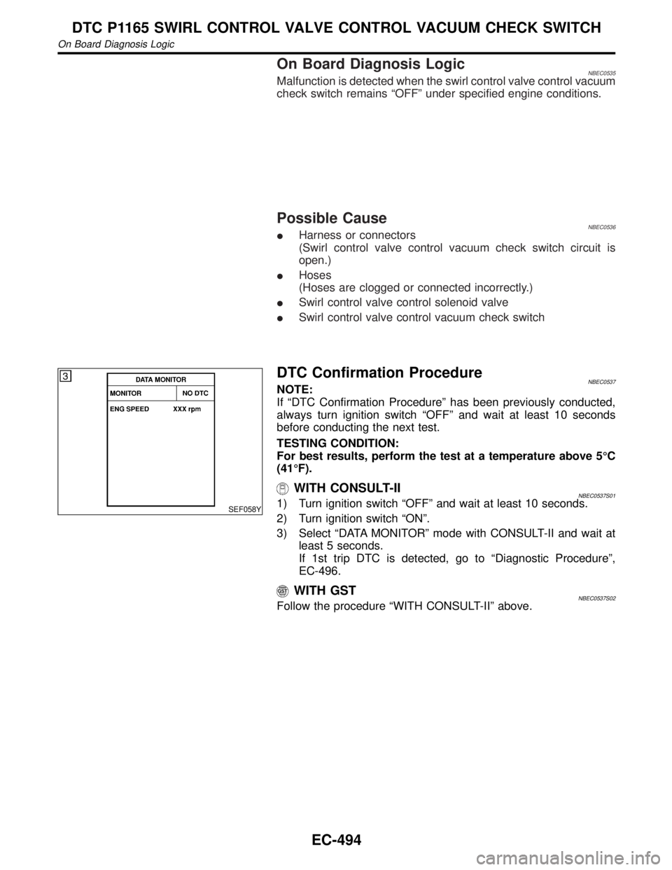
SEF058Y
DTC Confirmation ProcedureNBEC0537NOTE:
If ªDTC Confirmation Procedureº has been previously conducted,
always turn ignition switch ªOFFº and wait at least 10 seconds
before conducting the next test.
TESTING CONDITION:
For best results, perform the test at a temperature above 5ÉC
(41ÉF).
WITH CONSULT-IINBEC0537S011) Turn ignition switch ªOFFº and wait at least 10 seconds.
2) Turn ignition switch ªONº.
3) Select ªDATA MONITORº mode with CONSULT-II and wait at
least 5 seconds.
If 1st trip DTC is detected, go to ªDiagnostic Procedureº,
EC-496.
WITH GSTNBEC0537S02Follow the procedure ªWITH CONSULT-IIº above.
DTC P1165 SWIRL CONTROL VALVE CONTROL VACUUM CHECK SWITCH
On Board Diagnosis Logic
EC-494
Page 1031 of 2395
Diagnostic ProcedureNBEC0539
1 CHECK HOSES
1. Turn ignition switch ªOFFº.
2. Check hose for clogging or improper connection.
SEF109L
OK or NG
OK©GO TO 2.
NG©Repair or reconnect the hose.
2 CHECK SWIRL CONTROL VALVE CONTROL VACUUM CHECK SWITCH GROUND CIRCUIT FOR OPEN
AND SHORT
1. Disconnect swirl control valve control vacuum check switch harness connector.
SEF999Y
2. Check harness continuity between terminal 2 and ground. Refer to Wiring Diagram.
Continuity should exist.
3. Also check harness for short to power.
OK or NG
OK©GO TO 4.
NG©GO TO 3.
3 DETECT MALFUNCTIONING PART
Check the following.
IHarness connectors E1, M1 and M92, F27
IHarness for open between swirl control valve control vacuum check switch and engine ground
©Repair open circuit or short to power in harness connectors.
DTC P1165 SWIRL CONTROL VALVE CONTROL VACUUM CHECK SWITCH
Diagnostic Procedure
EC-496
Page 1033 of 2395
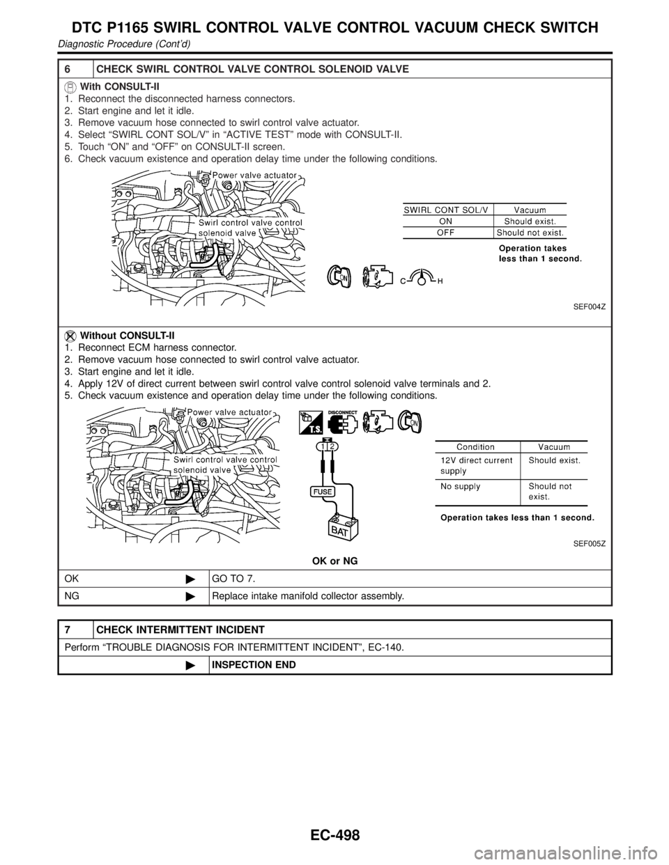
6 CHECK SWIRL CONTROL VALVE CONTROL SOLENOID VALVE
With CONSULT-II
1. Reconnect the disconnected harness connectors.
2. Start engine and let it idle.
3. Remove vacuum hose connected to swirl control valve actuator.
4. Select ªSWIRL CONT SOL/Vº in ªACTIVE TESTº mode with CONSULT-II.
5. Touch ªONº and ªOFFº on CONSULT-II screen.
6. Check vacuum existence and operation delay time under the following conditions.
SEF004Z
Without CONSULT-II
1. Reconnect ECM harness connector.
2. Remove vacuum hose connected to swirl control valve actuator.
3. Start engine and let it idle.
4. Apply 12V of direct current between swirl control valve control solenoid valve terminals and 2.
5. Check vacuum existence and operation delay time under the following conditions.
SEF005Z
OK or NG
OK©GO TO 7.
NG©Replace intake manifold collector assembly.
7 CHECK INTERMITTENT INCIDENT
Perform ªTROUBLE DIAGNOSIS FOR INTERMITTENT INCIDENTº, EC-140.
©INSPECTION END
DTC P1165 SWIRL CONTROL VALVE CONTROL VACUUM CHECK SWITCH
Diagnostic Procedure (Cont'd)
EC-498
Page 1046 of 2395
On Board Diagnosis LogicNBEC0576Malfunction is detected when
(Malfunction A)120É signal is not entered to ECM for the first few
seconds during engine cranking,
(Malfunction B)120É signal is not entered to ECM during engine
running,
(Malfunction C)120É signal cycle excessively changes during
engine running.
FAIL-SAFE MODENBEC0576S01When the ECM enters the fail-safe mode, the MIL illuminates.
Detected items Engine operating condition in fail-safe mode
Crankshaft position sensor (REF)
circuitCompression TDC signal (120É signal) is controlled by camshaft position sensor (PHASE)
signal and crankshaft position sensor (POS) signal. Ignition timing will be delayed 0É to 2É.
Possible CauseNBEC0577IHarness or connectors
(The crankshaft position sensor (REF) circuit is open or
shorted.)
ICrankshaft position sensor (REF)
IStarter motor (Refer to SC section.)
IStarting system circuit (Refer to SC section.)
IDead (Weak) battery
DTC Confirmation ProcedureNBEC0578NOTE:
IPerform ªPROCEDURE FOR MALFUNCTION Aº first. If 1st
trip DTC cannot be confirmed, perform ªPROCEDURE
FOR MALFUNCTION B AND Cº.
IIf ªDTC Confirmation Procedureº has been previously
conducted, always turn ignition switch ªOFFº and wait at least
10 seconds before conducting the next test.
TESTING CONDITION:
Before performing the following procedure, confirm that bat-
tery voltage is more than 10.5V at idle.
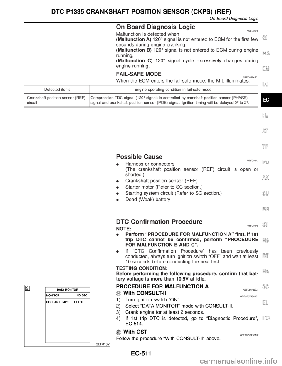
SEF013Y
PROCEDURE FOR MALFUNCTION ANBEC0578S01With CONSULT-IINBEC0578S01011) Turn ignition switch ªONº.
2) Select ªDATA MONITORº mode with CONSULT-II.
3) Crank engine for at least 2 seconds.
4) If 1st trip DTC is detected, go to ªDiagnostic Procedureº,
EC-514.
With GSTNBEC0578S0102Follow the procedure ªWith CONSULT-IIº above.
GI
MA
EM
LC
FE
AT
TF
PD
AX
SU
BR
ST
RS
BT
HA
SC
EL
IDX
DTC P1335 CRANKSHAFT POSITION SENSOR (CKPS) (REF)
On Board Diagnosis Logic
EC-511
Page 1062 of 2395
IEVAP purge line rubber tube bent.
IBlocked or bent rubber tube to EVAP control system pressure
sensor
ILoose or disconnected rubber tube
IEVAP canister vent control valve and the circuit
IEVAP canister purge volume control solenoid valve
IAbsolute pressure sensor
IFuel tank temperature sensor
IO-ring of EVAP canister vent control valve is missing or dam-
aged.
IWater separator
IEVAP canister is saturated with water.
IFuel level sensor and the circuit
IEVAP control system pressure sensor
SEF881X
SEF882X
SEF883X
DTC Confirmation ProcedureNBEC0317CAUTION:
Never remove fuel filler cap during the DTC confirmation pro-
cedure.
NOTE:
IIf DTC P1441 is displayed with P0440, perform TROUBLE
DIAGNOSIS FOR DTC P1441 first.
IIf ªDIAGNOSTIC TROUBLE CODE CONFIRMATION PRO-
CEDUREº has been previously conducted, always turn
ignition switch ªOFFº and wait at least 5 seconds before
conducting the next test.
IAfter repair, make sure that the hoses and clips are
installed properly.
TESTING CONDITION:
IOpen engine hood before conducting following proce-
dure.
IIf any of following condition is met just before the DTC
confirmation procedure, leave the vehicle for more than 1
hour.
a)Fuel filler cap is removed.
b)Refilled or drained the fuel.
c)EVAP component parts is/are removed.
IBefore performing the following procedure, confirm that
battery voltage is more than 11V at idle.
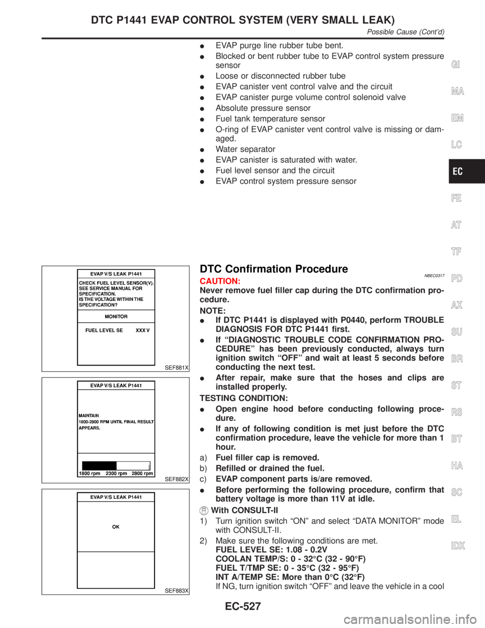
With CONSULT-II
1) Turn ignition switch ªONº and select ªDATA MONITORº mode
with CONSULT-II.
2) Make sure the following conditions are met.
FUEL LEVEL SE: 1.08 - 0.2V
COOLAN TEMP/S: 0 - 32ÉC (32 - 90ÉF)
FUEL T/TMP SE: 0 - 35ÉC (32 - 95ÉF)
INT A/TEMP SE: More than 0ÉC (32ÉF)
If NG, turn ignition switch ªOFFº and leave the vehicle in a cool
GI
MA
EM
LC
FE
AT
TF
PD
AX
SU
BR
ST
RS
BT
HA
SC
EL
IDX
DTC P1441 EVAP CONTROL SYSTEM (VERY SMALL LEAK)
Possible Cause (Cont'd)
EC-527
Page 1063 of 2395
place or refilling/draining fuel until the output voltage condition
of the ªFUEL LEVEL SEº meets within the range above and
leave the vehicle for more than 1 hour. Then start from step 1).
3) Turn ignition switch ªOFFº and wait at least 5 seconds.
4) Turn ignition switch ªONº.
5) Select ªEVAP VERY/SML LEAK P1441º of ªEVAPORATIVE
SYSTEMº in ªDTC WORK SUPPORTº mode with CONSULT-
II.
Follow the instruction displayed.
6) Make sure that ªOKº is displayed.
If ªNGº is displayed, refer to ªDiagnostic Procedureº, EC-529.
NOTE:
IIf the engine speed cannot be maintained within the range
displayed on CONSULT-II screen, go to ªBasic
inspectionº, EC-101.
IMake sure that EVAP hoses are connected to EVAP canis-
ter purge volume control solenoid valve properly.
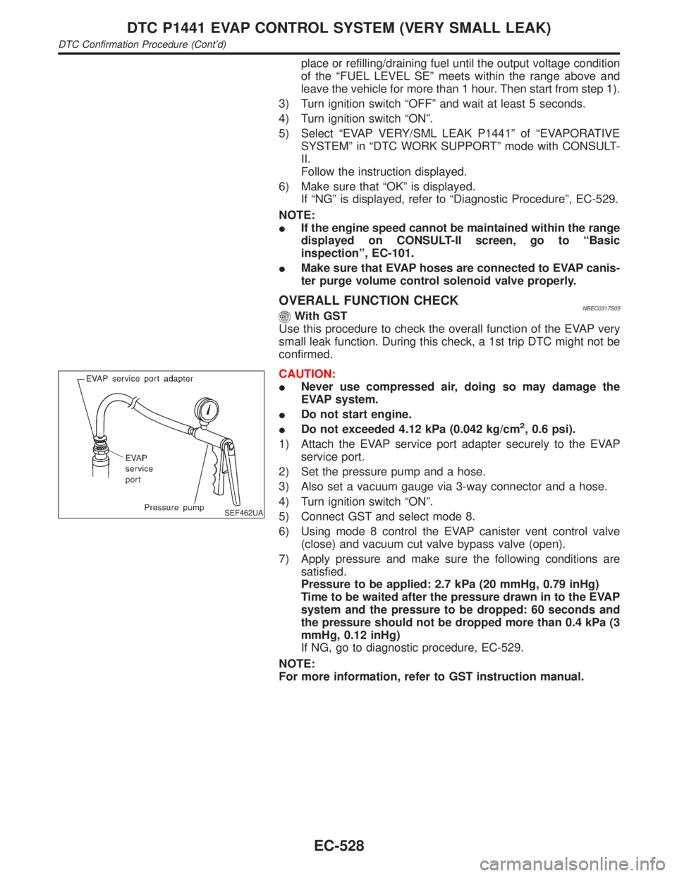
OVERALL FUNCTION CHECKNBEC0317S05With GST
Use this procedure to check the overall function of the EVAP very
small leak function. During this check, a 1st trip DTC might not be
confirmed.
SEF462UA
CAUTION:
INever use compressed air, doing so may damage the
EVAP system.
IDo not start engine.
IDo not exceeded 4.12 kPa (0.042 kg/cm
2, 0.6 psi).
1) Attach the EVAP service port adapter securely to the EVAP
service port.
2) Set the pressure pump and a hose.
3) Also set a vacuum gauge via 3-way connector and a hose.
4) Turn ignition switch ªONº.
5) Connect GST and select mode 8.
6) Using mode 8 control the EVAP canister vent control valve
(close) and vacuum cut valve bypass valve (open).
7) Apply pressure and make sure the following conditions are
satisfied.
Pressure to be applied: 2.7 kPa (20 mmHg, 0.79 inHg)
Time to be waited after the pressure drawn in to the EVAP
system and the pressure to be dropped: 60 seconds and
the pressure should not be dropped more than 0.4 kPa (3
mmHg, 0.12 inHg)
If NG, go to diagnostic procedure, EC-529.
NOTE:
For more information, refer to GST instruction manual.
DTC P1441 EVAP CONTROL SYSTEM (VERY SMALL LEAK)
DTC Confirmation Procedure (Cont'd)
EC-528
Page 1070 of 2395
11 CHECK EVAP CANISTER
Weigh the EVAP canister with the EVAP canister vent control valve attached.
The weight should be less than 1.8 kg (4.0 lb).
OK or NG
OK (With CONSULT-II)©GO TO 13.
OK (Without CONSULT-
II)©GO TO 14.
NG©GO TO 12.
12 DETECT MALFUNCTIONING PART
Check the following.
IEVAP canister for damage
IEVAP hose between EVAP canister and water separator for clogging or poor connection
©Repair hose or replace EVAP canister.
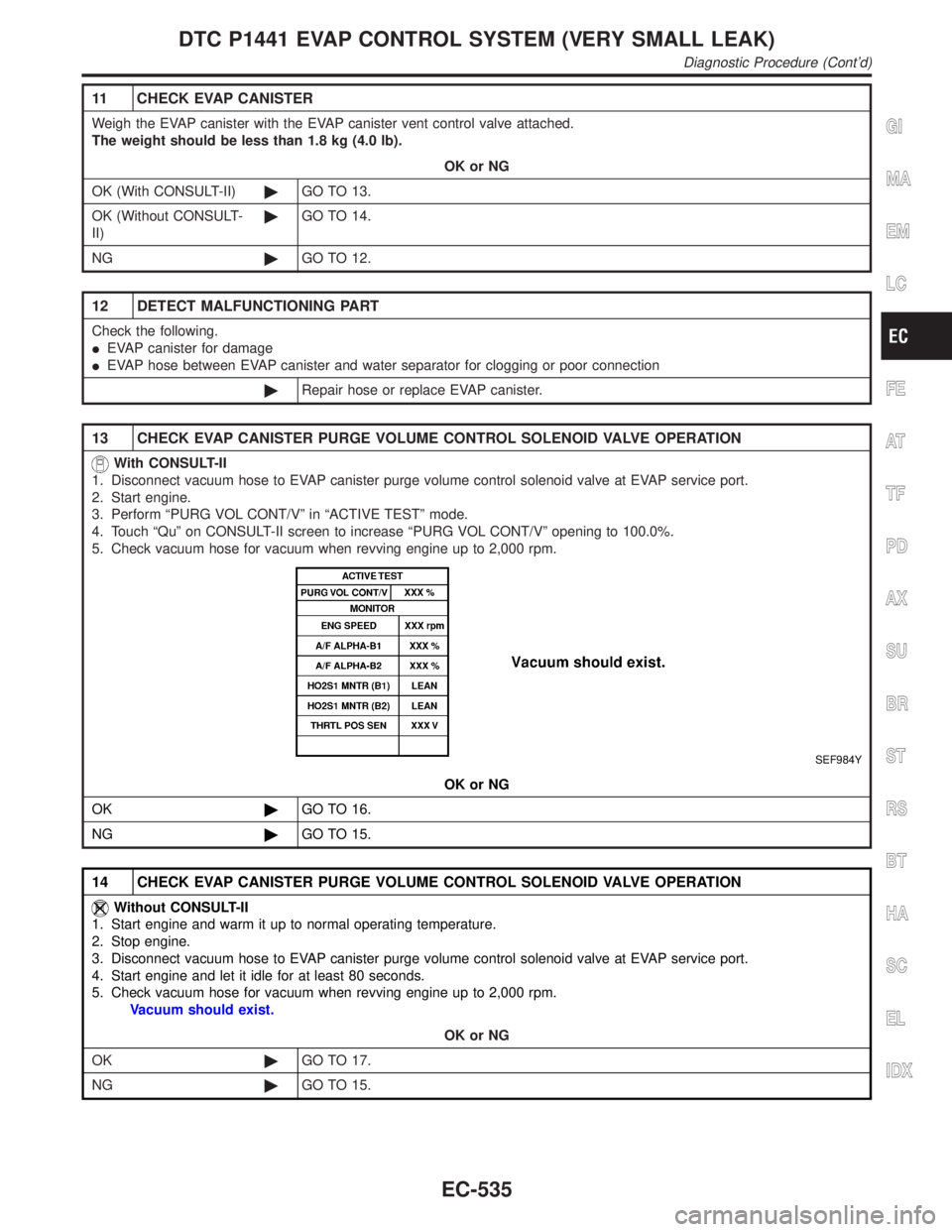
13 CHECK EVAP CANISTER PURGE VOLUME CONTROL SOLENOID VALVE OPERATION
With CONSULT-II
1. Disconnect vacuum hose to EVAP canister purge volume control solenoid valve at EVAP service port.
2. Start engine.
3. Perform ªPURG VOL CONT/Vº in ªACTIVE TESTº mode.
4. Touch ªQuº on CONSULT-II screen to increase ªPURG VOL CONT/Vº opening to 100.0%.
5. Check vacuum hose for vacuum when revving engine up to 2,000 rpm.
SEF984Y
OK or NG
OK©GO TO 16.
NG©GO TO 15.
14 CHECK EVAP CANISTER PURGE VOLUME CONTROL SOLENOID VALVE OPERATION
Without CONSULT-II
1. Start engine and warm it up to normal operating temperature.
2. Stop engine.
3. Disconnect vacuum hose to EVAP canister purge volume control solenoid valve at EVAP service port.
4. Start engine and let it idle for at least 80 seconds.
5. Check vacuum hose for vacuum when revving engine up to 2,000 rpm.
Vacuum should exist.
OK or NG
OK©GO TO 17.
NG©GO TO 15.
GI
MA
EM
LC
FE
AT
TF
PD
AX
SU
BR
ST
RS
BT
HA
SC
EL
IDX
DTC P1441 EVAP CONTROL SYSTEM (VERY SMALL LEAK)
Diagnostic Procedure (Cont'd)
EC-535
Page 1071 of 2395
15 CHECK VACUUM HOSE
Check vacuum hoses for clogging or disconnection. Refer to ªVacuum Hose Drawingº, EC-26.
OK or NG
OK (With CONSULT-II)©GO TO 16.
OK (Without CONSULT-
II)©GO TO 17.
NG©Repair or reconnect the hose.
16 CHECK EVAP CANISTER PURGE VOLUME CONTROL SOLENOID VALVE
With CONSULT-II
1. Start engine.
2. Perform ªPURG VOL CONT/Vº in ªACTIVE TESTº mode with CONSULT-II. Check that engine speed varies according
to the valve opening.
SEF985Y
OK or NG
OK©GO TO 18.
NG©GO TO 17.
DTC P1441 EVAP CONTROL SYSTEM (VERY SMALL LEAK)
Diagnostic Procedure (Cont'd)
EC-536