2001 INFINITI QX4 warning
[x] Cancel search: warningPage 2191 of 2395
6. If rack sliding force is not within specification, overhaul steer-
ing gear assembly.
7. If rack sliding force is OK, inspect steering column. Refer to
ªInspectionº, ªSTEERING WHEEL AND STEERING
COLUMNº, ST-14.
SST834-F
Checking Hydraulic SystemNBST0015Before starting, check belt tension, driving pulley and tire pressure.
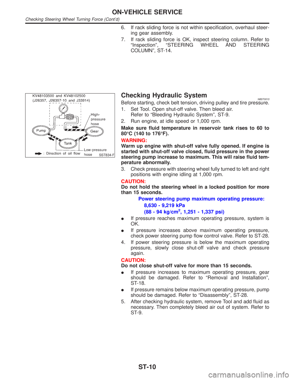
1. Set Tool. Open shut-off valve. Then bleed air.
Refer to ªBleeding Hydraulic Systemº, ST-9.
2. Run engine, at idle speed or 1,000 rpm.
Make sure fluid temperature in reservoir tank rises to 60 to
80ÉC (140 to 176ÉF).
WARNING:
Warm up engine with shut-off valve fully opened. If engine is
started with shut-off valve closed, fluid pressure in the power
steering pump increase to maximum. This will raise fluid tem-
perature abnormally.
3. Check pressure with steering wheel fully turned to left and right
positions with engine idling at 1,000 rpm.
CAUTION:
Do not hold the steering wheel in a locked position for more
than 15 seconds.
Power steering pump maximum operating pressure:
8,630 - 9,219 kPa
(88 - 94 kg/cm
2, 1,251 - 1,337 psi)
IIf pressure reaches maximum operating pressure, system is
OK.
IIf pressure increases above maximum operating pressure,
check power steering pump flow control valve. Refer to ST-28.
4. If power steering pressure is below the maximum operating
pressure, slowly close shut-off valve and check pressure
again.
CAUTION:
Do not close shut-off valve for more than 15 seconds.
IIf pressure increases to maximum operating pressure, gear
should be damaged. Refer to ªRemoval and Installationº,
ST-18.
IIf pressure remains below maximum operating pressure, pump
should be damaged. Refer to ªDisassemblyº, ST-28.
5. After checking hydraulic system, remove Tool and add fluid as
necessary. Then completely bleed air out of system. Refer to
ST-9.
ON-VEHICLE SERVICE
Checking Steering Wheel Turning Force (Cont'd)
ST-10
Page 2222 of 2395
SFA614B
SFA234AC
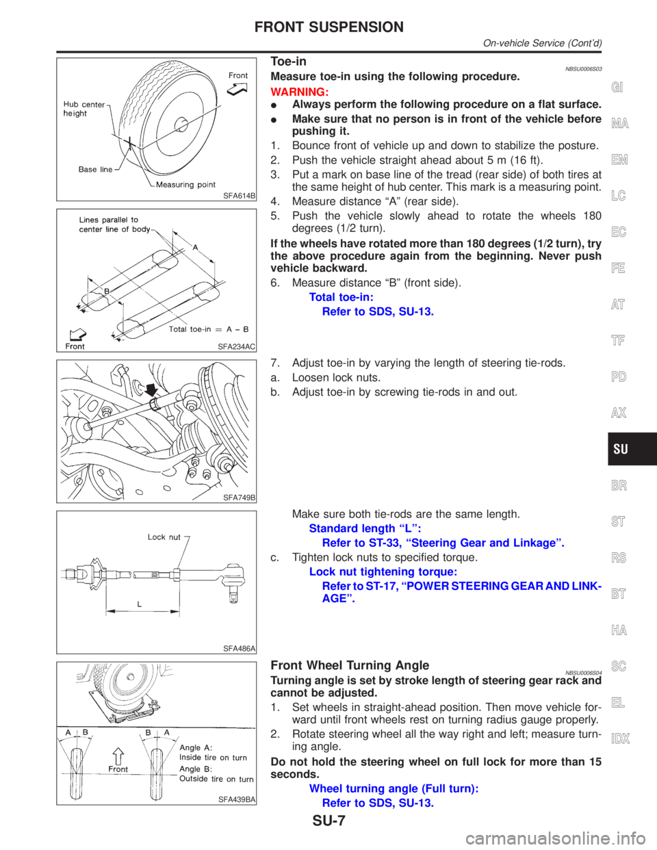
Toe-inNBSU0006S03Measure toe-in using the following procedure.
WARNING:
IAlways perform the following procedure on a flat surface.
IMake sure that no person is in front of the vehicle before
pushing it.
1. Bounce front of vehicle up and down to stabilize the posture.
2. Push the vehicle straight ahead about 5 m (16 ft).
3. Put a mark on base line of the tread (rear side) of both tires at
the same height of hub center. This mark is a measuring point.
4. Measure distance ªAº (rear side).
5. Push the vehicle slowly ahead to rotate the wheels 180
degrees (1/2 turn).
If the wheels have rotated more than 180 degrees (1/2 turn), try
the above procedure again from the beginning. Never push
vehicle backward.
6. Measure distance ªBº (front side).
Total toe-in:
Refer to SDS, SU-13.
SFA749B
7. Adjust toe-in by varying the length of steering tie-rods.
a. Loosen lock nuts.
b. Adjust toe-in by screwing tie-rods in and out.
SFA486A
Make sure both tie-rods are the same length.
Standard length ªLº:
Refer to ST-33, ªSteering Gear and Linkageº.
c. Tighten lock nuts to specified torque.
Lock nut tightening torque:
Refer to ST-17, ªPOWER STEERING GEAR AND LINK-
AGEº.
SFA439BA
Front Wheel Turning AngleNBSU0006S04Turning angle is set by stroke length of steering gear rack and
cannot be adjusted.
1. Set wheels in straight-ahead position. Then move vehicle for-
ward until front wheels rest on turning radius gauge properly.
2. Rotate steering wheel all the way right and left; measure turn-
ing angle.
Do not hold the steering wheel on full lock for more than 15
seconds.
Wheel turning angle (Full turn):
Refer to SDS, SU-13.
GI
MA
EM
LC
EC
FE
AT
TF
PD
AX
BR
ST
RS
BT
HA
SC
EL
IDX
FRONT SUSPENSION
On-vehicle Service (Cont'd)
SU-7
Page 2224 of 2395
SFA956A
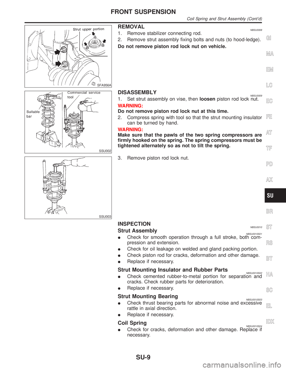
REMOVALNBSU00081. Remove stabilizer connecting rod.
2. Remove strut assembly fixing bolts and nuts (to hood-ledge).
Do not remove piston rod lock nut on vehicle.
SSU002
DISASSEMBLYNBSU00091. Set strut assembly on vise, thenloosenpiston rod lock nut.
WARNING:
Do not remove piston rod lock nut at this time.
2. Compress spring with tool so that the strut mounting insulator
can be turned by hand.
WARNING:
Make sure that the pawls of the two spring compressors are
firmly hooked on the spring. The spring compressors must be
tightened alternately so as not to tilt the spring.
SSU003
3. Remove piston rod lock nut.
INSPECTIONNBSU0010Strut AssemblyNBSU0010S01ICheck for smooth operation through a full stroke, both com-
pression and extension.
ICheck for oil leakage on welded and gland packing portion.
ICheck piston rod for cracks, deformation and other damage.
IReplace if necessary.
Strut Mounting Insulator and Rubber PartsNBSU0010S02ICheck cemented rubber-to-metal portion for separation and
cracks. Check rubber parts for deterioration.
IReplace if necessary.
Strut Mounting BearingNBSU0010S03ICheck thrust bearing parts for abnormal noise and excessive
rattle in axial direction.
IReplace if necessary.
Coil SpringNBSU0010S04ICheck for cracks, deformation and other damage. Replace if
necessary.
GI
MA
EM
LC
EC
FE
AT
TF
PD
AX
BR
ST
RS
BT
HA
SC
EL
IDX
FRONT SUSPENSION
Coil Spring and Strut Assembly (Cont'd)
SU-9
Page 2236 of 2395
TRANSFER
SECTION
TF
CONTENTS
PRECAUTIONS...............................................................3
Supplemental Restraint System (SRS)²AIR
BAG²and²SEAT BELT PRE-TENSIONER²...............3
Precautions ..................................................................3
Service Notice..............................................................4
Wiring Diagrams and Trouble Diagnosis .....................4
PREPARATION...............................................................5
Special Service Tools ..................................................5
Commercial Service Tools ...........................................9
ALL-MODE 4WD SYSTEM...........................................10
Cross-sectional View .................................................10
Control System .......................................................... 11
ALL-MODE 4WD TRANSFER BASIC CONTROL........12
HYDRAULIC CONTROL CIRCUITS...........................12
OUTLINE................................................................12
CONTROL SYSTEM DIAGRAM................................13
INDICATIONS OF 4WD WARNING LAMP..................13
Location of Electrical Parts ........................................14
Description of Electrical Parts ...................................15
TRANSFER MOTOR................................................15
WAIT DETECTION SWITCH.....................................15
2-4WD SHIFT SOLENOID VALVE.............................16
LINE PRESSURE SWITCH.......................................16
Circuit Diagram for Quick Pinpoint Check.................17
Wiring Diagram - TF -................................................18
ON BOARD DIAGNOSTIC SYSTEM
DESCRIPTION...............................................................27
Trouble Diagnosis without CONSULT-II ....................27
DESCRIPTION........................................................27
SELF-DIAGNOSTIC PROCEDURE............................28
INDICATIONS OF 4WD WARNING LAMP..................29
Trouble Diagnosis with CONSULT-II .........................30
SELF-DIAGNOSIS...................................................30
SELF-DIAGNOSTIC ITEMS......................................31
DATA MONITOR......................................................33
DATA MONITOR ITEMS...........................................34
REFERENCE VALUE IN DATA MONITOR MODE......36
WORK SUPPORT....................................................38
CLUTCH FORCE RELEASE LIMIT ADJUSTMENT.....39
TROUBLE DIAGNOSIS - INTRODUCTION..................41Introduction ................................................................41
DESCRIPTION........................................................41
DIAGNOSTIC WORKSHEET.....................................41
Work Flow ..................................................................43
HOW TO PERFORM TROUBLE DIAGNOSES FOR
QUICK AND ACCURATE REPAIR
.............................43
TROUBLE DIAGNOSIS - BASIC INSPECTION...........44
Listen to Customer Complaints .................................44
Transfer Fluid Check .................................................44
Road Test...................................................................44
PREPARATION FOR ROAD TEST............................44
1. CHECK BEFORE ENGINE IS STARTED...............45
2. CHECK AT IDLE..................................................47
3. CRUISE TEST.....................................................51
TROUBLE DIAGNOSIS - GENERAL
DESCRIPTION...............................................................54
Transfer Control Unit Terminals and Reference
Value ..........................................................................54
REMOVAL AND INSTALLATION OF TRANSFER
CONTROL UNIT
......................................................54
INSPECTION OF TRANSFER CONTROL UNIT..........54
TRANSFER CONTROL UNIT INSPECTION TABLE....55
VEHICLE SPEED SENSOR (FRONT
REVOLUTION SENSOR)..............................................61
Diagnostic Procedure ................................................61
4WD SOLENOID VALVE...............................................64
Diagnostic Procedure ................................................64
2-4WD SHIFT SOLENOID VALVE AND 4WD
SHIFT SWITCH..............................................................66
Diagnostic Procedure ................................................66
TRANSFER MOTOR AND TRANSFER MOTOR
RELAY...........................................................................70
Diagnostic Procedure ................................................70
TRANSFER FLUID TEMPERATURE SENSOR............73
Diagnostic Procedure ................................................73
ATP SWITCH, WAIT DETECTION SWITCH AND
NEUTRAL-4LO SWITCH...............................................76
Diagnostic Procedure ................................................76
CLUTCH PRESSURE SWITCH....................................80
Diagnostic Procedure ................................................80
GI
MA
EM
LC
EC
FE
AT
PD
AX
SU
BR
ST
RS
BT
HA
SC
EL
IDX
Page 2237 of 2395
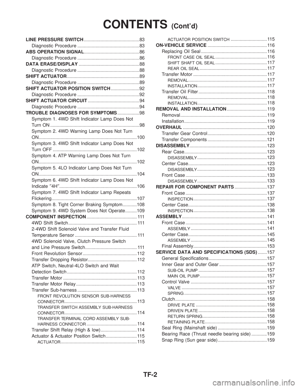
LINE PRESSURE SWITCH...........................................83
Diagnostic Procedure ................................................83
ABS OPERATION SIGNAL...........................................86
Diagnostic Procedure ................................................86
DATA ERASE/DISPLAY...............................................88
Diagnostic Procedure ................................................88
SHIFT ACTUATOR........................................................89
Diagnostic Procedure ................................................89
SHIFT ACTUATOR POSITION SWITCH......................92
Diagnostic Procedure ................................................92
SHIFT ACTUATOR CIRCUIT........................................94
Diagnostic Procedure ................................................94
TROUBLE DIAGNOSES FOR SYMPTOMS.................98
Symptom 1. 4WD Shift Indicator Lamp Does Not
Turn ON .....................................................................98
Symptom 2. 4WD Warning Lamp Does Not Turn
ON............................................................................100
Symptom 3. 4WD Shift Indicator Lamp Does Not
Turn OFF .................................................................102
Symptom 4. ATP Warning Lamp Does Not Turn
ON............................................................................102
Symptom 5. 4LO Indicator Lamp Does Not Turn
ON............................................................................104
Symptom 6. 4WD Shift Indicator Lamp Does Not
Indicate²4H²............................................................106
Symptom 7. 4WD Shift Indicator Lamp Repeats
Flickering..................................................................107
Symptom 8. Tight Corner Braking Symptom...........108
Symptom 9. 4WD System Does Not Operate.........109
COMPONENT INSPECTION....................................... 111
4WD Shift Switch ..................................................... 111
2-4WD Shift Solenoid Valve and Transfer Fluid
Temperature Sensor ................................................ 111
4WD Solenoid Valve, Clutch Pressure Switch
and Line Pressure Switch........................................ 111
Front Revolution Sensor .......................................... 112
Transfer Dropping Resistor...................................... 112
ATP Switch, Neutral-4LO Switch and Wait
Detection Switch ...................................................... 112
Transfer Motor ......................................................... 113
Transfer Motor Relay ............................................... 113
Transfer Sub-harness .............................................. 113
FRONT REVOLUTION SENSOR SUB-HARNESS
CONNECTOR
........................................................ 113
TRANSFER SWITCH ASSEMBLY SUB-HARNESS
CONNECTOR
........................................................ 114
TRANSFER TERMINAL CORD ASSEMBLY SUB-
HARNESS CONNECTOR
....................................... 114
Transfer Shift Relay (High & low) ............................ 114
Actuator & Actuator Position Switch ........................ 115
ACTUATOR........................................................... 115
ACTUATOR POSITION SWITCH............................ 115
ON-VEHICLE SERVICE.............................................. 116
Replacing Oil Seal ................................................... 116
FRONT CASE OIL SEAL........................................ 116
SHIFT SHAFT OIL SEAL........................................ 117
REAR OIL SEAL.................................................... 117
Transfer Motor ......................................................... 117
REMOVAL............................................................. 117
INSTALLATION...................................................... 117
Transfer Oil Filter ..................................................... 118
REMOVAL............................................................. 118
INSTALLATION...................................................... 118
REMOVAL AND INSTALLATION............................... 119
Removal ................................................................... 119
Installation ................................................................ 119
OVERHAUL.................................................................120
Transfer Gear Control ..............................................120
Transfer Components ..............................................121
DISASSEMBLY............................................................123
Rear Case................................................................123
DISASSEMBLY......................................................123
Center Case.............................................................123
DISASSEMBLY......................................................123
Front Case ...............................................................133
DISASSEMBLY......................................................133
REPAIR FOR COMPONENT PARTS.........................137
Front Case ...............................................................137
INSPECTION.........................................................137
Center Case.............................................................138
INSPECTION.........................................................138
ASSEMBLY..................................................................141
Front Case ...............................................................141
ASSEMBLY...........................................................141
Center Case.............................................................145
ASSEMBLY...........................................................145
Final Assembly.........................................................153
SERVICE DATA AND SPECIFICATIONS (SDS).......157
General Specifications .............................................157
Inner Gear and Outer Gear .....................................157
SUB-OIL PUMP.....................................................157
MAIN OIL PUMP....................................................157
Control Valve ...........................................................157
VALVE..................................................................157
SPRING................................................................157
Clutch .......................................................................158
DRIVE PLATE.......................................................158
DRIVEN PLATE.....................................................158
RETURN SPRING..................................................158
RETAINING PLATE................................................158
Seal Ring (Mainshaft side) ......................................159
Bearing Race (Thrust needle bearing side) ............159
Snap Ring (Sun gear side) ......................................159
CONTENTS(Cont'd)
TF-2
Page 2238 of 2395
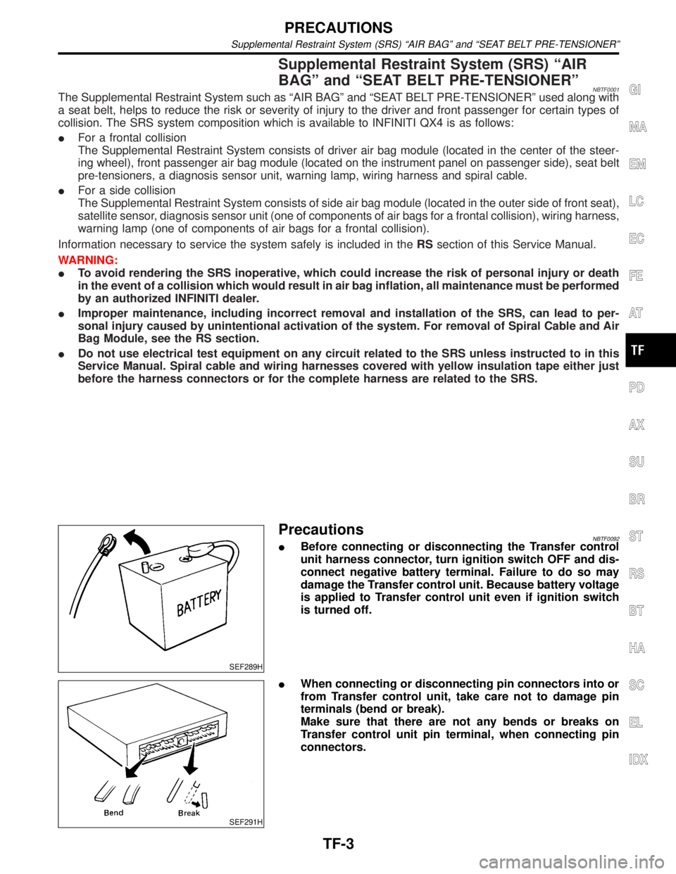
Supplemental Restraint System (SRS) ªAIR
BAGº and ªSEAT BELT PRE-TENSIONERº
NBTF0001The Supplemental Restraint System such as ªAIR BAGº and ªSEAT BELT PRE-TENSIONERº used along with
a seat belt, helps to reduce the risk or severity of injury to the driver and front passenger for certain types of
collision. The SRS system composition which is available to INFINITI QX4 is as follows:
IFor a frontal collision
The Supplemental Restraint System consists of driver air bag module (located in the center of the steer-
ing wheel), front passenger air bag module (located on the instrument panel on passenger side), seat belt
pre-tensioners, a diagnosis sensor unit, warning lamp, wiring harness and spiral cable.
IFor a side collision
The Supplemental Restraint System consists of side air bag module (located in the outer side of front seat),
satellite sensor, diagnosis sensor unit (one of components of air bags for a frontal collision), wiring harness,
warning lamp (one of components of air bags for a frontal collision).
Information necessary to service the system safely is included in theRSsection of this Service Manual.
WARNING:
ITo avoid rendering the SRS inoperative, which could increase the risk of personal injury or death
in the event of a collision which would result in air bag inflation, all maintenance must be performed
by an authorized INFINITI dealer.
IImproper maintenance, including incorrect removal and installation of the SRS, can lead to per-
sonal injury caused by unintentional activation of the system. For removal of Spiral Cable and Air
Bag Module, see the RS section.
IDo not use electrical test equipment on any circuit related to the SRS unless instructed to in this
Service Manual. Spiral cable and wiring harnesses covered with yellow insulation tape either just
before the harness connectors or for the complete harness are related to the SRS.
SEF289H
PrecautionsNBTF0092IBefore connecting or disconnecting the Transfer control
unit harness connector, turn ignition switch OFF and dis-
connect negative battery terminal. Failure to do so may
damage the Transfer control unit. Because battery voltage
is applied to Transfer control unit even if ignition switch
is turned off.
SEF291H
IWhen connecting or disconnecting pin connectors into or
from Transfer control unit, take care not to damage pin
terminals (bend or break).
Make sure that there are not any bends or breaks on
Transfer control unit pin terminal, when connecting pin
connectors.
GI
MA
EM
LC
EC
FE
AT
PD
AX
SU
BR
ST
RS
BT
HA
SC
EL
IDX
PRECAUTIONS
Supplemental Restraint System (SRS) ªAIR BAGº and ªSEAT BELT PRE-TENSIONERº
TF-3
Page 2247 of 2395
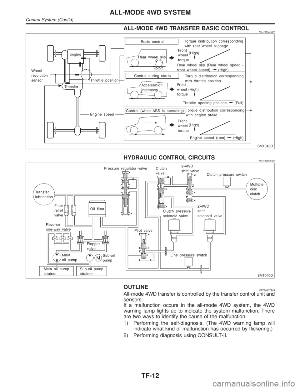
ALL-MODE 4WD TRANSFER BASIC CONTROLNBTF0007S01
SMT043D
HYDRAULIC CONTROL CIRCUITSNBTF0007S02
SMT040D
OUTLINENBTF0007S03All-mode 4WD transfer is controlled by the transfer control unit and
sensors.
If a malfunction occurs in the all-mode 4WD system, the 4WD
warning lamp lights up to indicate the system malfunction. There
are two ways to identify the cause of the malfunction.
1) Performing the self-diagnosis. (The 4WD warning lamp will
indicate what kind of malfunction has occurred by flickering.)
2) Performing diagnosis using CONSULT-II.
ALL-MODE 4WD SYSTEM
Control System (Cont'd)
TF-12
Page 2248 of 2395

CONTROL SYSTEM DIAGRAMNBTF0007S04
SMT763D
INDICATIONS OF 4WD WARNING LAMPNBTF0007S05
Condition Content 4WD warning lamp
During self-diagnosis Indicates the malfunction position by number of flickers. Flickers at malfunction mode.
Lamp check*Checks the lamp by turning ON during engine starting. After
engine starts, it turns OFF if there are no malfunctions.ON
Malfunction in 4WD system*Turns ON to indicate malfunction. When ignition switch is
turned to ªOFFº or the malfunction is corrected, it turns OFF.ON
When vehicle is driven with different
diameters of front and rear tiresFlickers once every 2 seconds.
Turns OFF when ignition switch is ªOFFº.Flickers once every 2 sec-
onds.
High fluid temperature in transfer
unitWhen fluid temperature is high or fluid temperature sensor
circuit is shorted, it flickers twice every second.
It turns OFF when fluid temperature becomes normal.Flickers twice a second.
Other than above (System is nor-
mal.)Lamp is OFF. OFF
*: When 4WD warning lamp is ON, all the 4WD shift indicator lamps turn OFF.
GI
MA
EM
LC
EC
FE
AT
PD
AX
SU
BR
ST
RS
BT
HA
SC
EL
IDX
ALL-MODE 4WD SYSTEM
Control System (Cont'd)
TF-13