Page 1539 of 2395

DATA TRANSMITTINGNBEL0180S05When contact to the Communicator Response Center is made,
vehicle sends electrical data including type of activation (i.e., emer-
gency call or alarm notification), vehicle location, time, etc.
SLEEP/WAKE UP CONTROLNBEL0180S063 minutes after the ignition switch is turned OFF, the system goes
into the SLEEP MODE to save battery power supply. Communica-
tion with Communicator Response Center is not available in the
SLEEP MODE.
To wake up the system, perform either of the following operations.
ITurn Ignition switch ON.
IPull back door outside handle for more than 10 seconds.
(Operation for door unlock function)
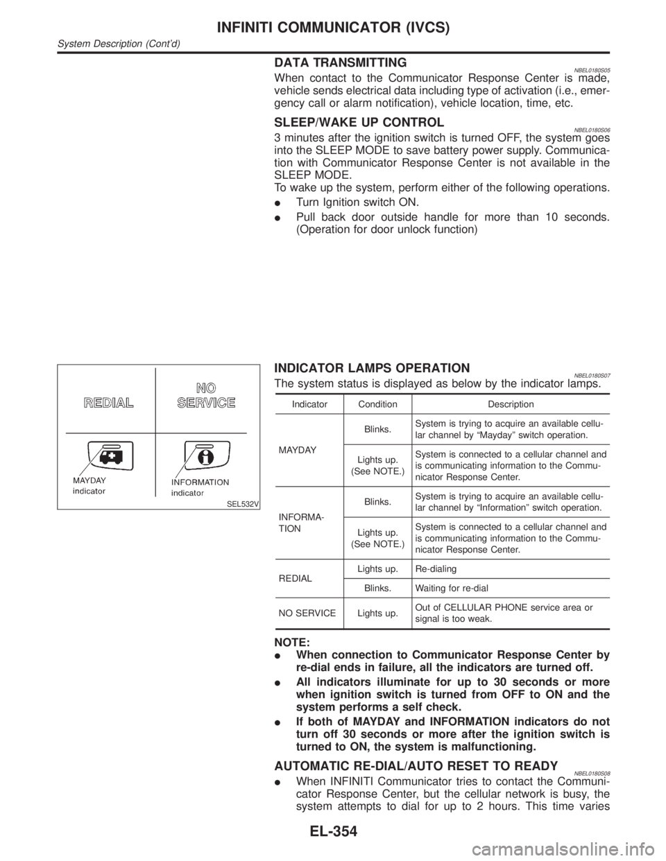
SEL532V
INDICATOR LAMPS OPERATIONNBEL0180S07The system status is displayed as below by the indicator lamps.
Indicator Condition Description
MAYDAYBlinks.System is trying to acquire an available cellu-
lar channel by ªMaydayº switch operation.
Lights up.
(See NOTE.)System is connected to a cellular channel and
is communicating information to the Commu-
nicator Response Center.
INFORMA-
TIONBlinks.System is trying to acquire an available cellu-
lar channel by ªInformationº switch operation.
Lights up.
(See NOTE.)System is connected to a cellular channel and
is communicating information to the Commu-
nicator Response Center.
REDIALLights up. Re-dialing
Blinks. Waiting for re-dial
NO SERVICE Lights up.Out of CELLULAR PHONE service area or
signal is too weak.
NOTE:
IWhen connection to Communicator Response Center by
re-dial ends in failure, all the indicators are turned off.
IAll indicators illuminate for up to 30 seconds or more
when ignition switch is turned from OFF to ON and the
system performs a self check.
IIf both of MAYDAY and INFORMATION indicators do not
turn off 30 seconds or more after the ignition switch is
turned to ON, the system is malfunctioning.
AUTOMATIC RE-DIAL/AUTO RESET TO READYNBEL0180S08IWhen INFINITI Communicator tries to contact the Communi-
cator Response Center, but the cellular network is busy, the
system attempts to dial for up to 2 hours. This time varies
INFINITI COMMUNICATOR (IVCS)
System Description (Cont'd)
EL-354
Page 1556 of 2395
SEL976VA
POWER SUPPLY AND GROUND CIRCUIT FOR IVCS
UNIT CHECK
NBEL0184S05Main Power Supply Circuit CheckNBEL0184S0501
Terminal Ignition switch
(+) (þ) OFF ACC ON
18 GroundBattery volt-
ageBattery volt-
ageBattery volt-
age
2 Ground 0V 0VBattery volt-
age
If NG, check the following:
I15A fuse [No. 4, located in fuse and fusible link box]
I7.5A fuse [No. 11, located in fuse block (J/B)]
IHarness for open or short between fuse and IVCS unit
SEL519VB
Ground Circuit CheckNBEL0184S0502
Terminals Continuity
17 - Ground Yes
GI
MA
EM
LC
EC
FE
AT
TF
PD
AX
SU
BR
ST
RS
BT
HA
SC
IDX
INFINITI COMMUNICATOR (IVCS)
Trouble Diagnoses (Cont'd)
EL-371
Page 1569 of 2395

NOTE:
If an unavailable number is input as ªSYS IDº, ªGR IDº or
ªOVERLOAD CLASSº, CONSULT-II may be locked. In such
cases, disconnect the vehicle battery cable once and then
setup the system again.
5. Touch ªENTERº.
SEL465W
6. Touch ªOKº.
7. Carry out the next system setting or contact Communicator
Response Center and inform them that data has been updated
or IVCS unit has been replaced. For details, refer to EL-381.
NOTE:
Whenever the phone number is updated or the IVCS unit is
replaced, the INFINITI Communicator system automatically
contacts the Communicator Response Center the first time the
vehicle is stared.
SEL466W
STOLEN VEHICLE TRACKING/ALARM NOTIFICATION
SETTING CHECK
NBEL0187S051. Touch ªCONFIGURATIONº.
2. Touch ªVEHICLE TRACKINGº or ªALARM NOTIFICATIONº.
SEL467W
3. This function should always be ªONº (function activate.)
NOTE:
IIf either setting is ªOFFº, contact the Communicator
Response Center at 1-888-427-4812 to verify the system
setting.
IWhenever dialing the above number, information about
the vehicle is required by the operator. For details, refer to
EL-348.
INFINITI COMMUNICATOR (IVCS)
System Setting (When IVCS Unit is Replaced) (Cont'd)
EL-384
Page 1602 of 2395

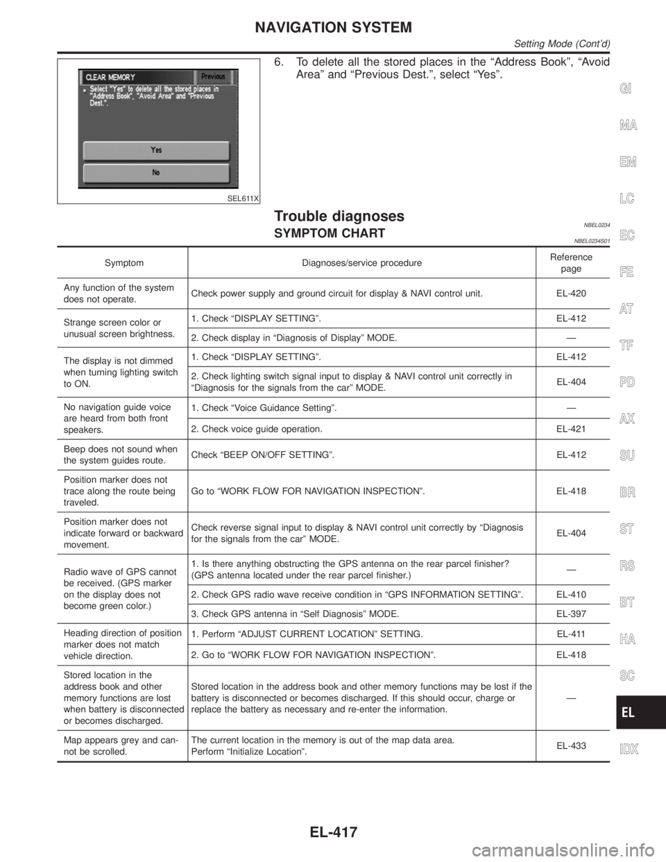
SEL611X
6. To delete all the stored places in the ªAddress Bookº, ªAvoid
Areaº and ªPrevious Dest.º, select ªYesº.
Trouble diagnosesNBEL0234SYMPTOM CHARTNBEL0234S01
Symptom Diagnoses/service procedureReference
page
Any function of the system
does not operate.Check power supply and ground circuit for display & NAVI control unit. EL-420
Strange screen color or
unusual screen brightness.1. Check ªDISPLAY SETTINGº. EL-412
2. Check display in ªDiagnosis of Displayº MODE. Ð
The display is not dimmed
when turning lighting switch
to ON.1. Check ªDISPLAY SETTINGº. EL-412
2. Check lighting switch signal input to display & NAVI control unit correctly in
ªDiagnosis for the signals from the carº MODE.EL-404
No navigation guide voice
are heard from both front
speakers.1. Check ªVoice Guidance Settingº. Ð
2. Check voice guide operation. EL-421
Beep does not sound when
the system guides route.Check ªBEEP ON/OFF SETTINGº. EL-412
Position marker does not
trace along the route being
traveled.Go to ªWORK FLOW FOR NAVIGATION INSPECTIONº. EL-418
Position marker does not
indicate forward or backward
movement.Check reverse signal input to display & NAVI control unit correctly by ªDiagnosis
for the signals from the carº MODE.EL-404
Radio wave of GPS cannot
be received. (GPS marker
on the display does not
become green color.)1. Is there anything obstructing the GPS antenna on the rear parcel finisher?
(GPS antenna located under the rear parcel finisher.)Ð
2. Check GPS radio wave receive condition in ªGPS INFORMATION SETTINGº. EL-410
3. Check GPS antenna in ªSelf Diagnosisº MODE. EL-397
Heading direction of position
marker does not match
vehicle direction.1. Perform ªADJUST CURRENT LOCATIONº SETTING. EL-411
2. Go to ªWORK FLOW FOR NAVIGATION INSPECTIONº. EL-418
Stored location in the
address book and other
memory functions are lost
when battery is disconnected
or becomes discharged.Stored location in the address book and other memory functions may be lost if the
battery is disconnected or becomes discharged. If this should occur, charge or
replace the battery as necessary and re-enter the information.Ð
Map appears grey and can-
not be scrolled.The current location in the memory is out of the map data area.
Perform ªInitialize Locationº.EL-433
GI
MA
EM
LC
EC
FE
AT
TF
PD
AX
SU
BR
ST
RS
BT
HA
SC
IDX
NAVIGATION SYSTEM
Setting Mode (Cont'd)
EL-417
Page 1605 of 2395
SEL693VD
POWER SUPPLY AND GROUND CIRCUIT CHECK FOR
DISPLAY & NAVI CONTROL UNIT
=NBEL0234S04Power Supply Circuit CheckNBEL0234S0401
Terminal Ignition switch
(+) (þ) OFF ACC ON
1 Ground Battery voltage Battery voltage Battery voltage
2 Ground Battery voltage Battery voltage Battery voltage
5 Ground 0V 0V Battery voltage
6 Ground 0V Battery voltage Battery voltage
If NG, check the following.
I7.5A fuse [No. 11, located in the fuse block (J/B)]
I10A fuse [No. 10, located in the fuse block (J/B)]
I15A fuse [No. 4, located in the fuse block (J/B)]
IHarness for open or short between fuse and display & NAVI
control unit
SEL694VD
Ground Circuit CheckNBEL0234S0402
Terminals Continuity
3 - Ground Yes
4 - Ground Yes
NAVIGATION SYSTEM
Trouble diagnoses (Cont'd)
EL-420
Page 1657 of 2395

NBEM0007
SEM480G
SEM481G
JEM482G
SEM387C
1. Warm up engine.
2. Turn ignition switch OFF.
3. Release fuel pressure.
Refer to EC-39, ªFuel Pressure Releaseº.
4. Remove engine cover and throttle wire.
5. Remove air duct with air cleaner case.
6. Remove harness connectors and harness brackets around
ignition coils.
7. Remove throttle body.
8. Disconnect ignition coil with power transistor harness
connectors, then remove ignition coils.
9. Remove all spark plugs.
IClean area around plug with compressed air before removing
the spark plug.
10. Attach a compression tester to No. 1 cylinder.
11. Depress accelerator pedal fully to keep throttle valve wide
open.
12. Crank engine and record highest gauge indication.
13. Repeat the measurement on each cylinder as shown above.
IAlways use a fully-charged battery to obtain specified
engine speed.
Unit: kPa (kg/cm2, psi)/rpm
Standard MinimumDifference limit between
cylinders
1,275 (13.0, 185)/300 981 (10.0, 142)/300 98 (1.0, 14)/300
14. If compression in one or more cylinders is low:
a. Pour a small amount of engine oil into cylinders through spark
plug holes.
b. Retest compression.
IIf adding oil helps compression, piston rings may be worn
or damaged. If so, replace piston rings after checking pis-
ton.
IIf pressure stays low, a valve may be sticking or seating
improperly. Inspect and repair valve and valve seat. (Refer
to SDS, EM-76 and EM-79.) If valve or valve seat is dam-
aged excessively, replace them.
IIf compression stays low in two cylinders that are next to
each other:
a) The cylinder head gasket may be leaking, or
b) Both cylinders may have valve component damage. Inspect
and repair as necessary.
15. Install parts in reverse order of removal.
16. Perform ªSelf-diagnosis Procedureº referring to EC-72, ªHow to
Erase DTCº if any DTC appears.
MEASUREMENT OF COMPRESSION PRESSURE
EM-14
Page 1658 of 2395
ComponentsNBEM0008
SEM583G
RemovalNBEM0009WARNING:
IPlace vehicle on a flat and solid surface.
IYou should not remove oil pan until exhaust system and
cooling system have completely cooled off.
Otherwise, you may burn yourself and/or fire may break
out in the fuel line.
IWhen removing front engine mounting nuts, lift up slightly
engine for safety work.
CAUTION:
When removing the aluminum oil pan from engine, first
remove the crankshaft position sensors (POS and REF) from
the assembly.
Be careful not to damage sensor edges and signal plate teeth.
1. Remove front RH and LH wheels.
2. Remove battery.
3. Remove oil level gauge.
4. Remove engine undercover.
5. Remove suspension member stay.
6. Drain engine coolant from radiator drain plug.
7. Disconnect A/T oil cooler hoses.
8. Drain engine oil.
GI
MA
LC
EC
FE
AT
TF
PD
AX
SU
BR
ST
RS
BT
HA
SC
EL
IDX
OIL PAN
Components
EM-15
Page 1666 of 2395

CAUTION:
IAfter removing timing chain, do not turn crankshaft and
camshaft separately, or valves will strike piston heads.
IWhen installing camshafts, chain tensioners, oil seals, or
other sliding parts, lubricate contacting surfaces with new
engine oil.
IApply new engine oil to bolt threads and seat surfaces
when installing camshaft sprockets and crankshaft pulley.
IBefore disconnecting fuel hose, release fuel pressure.
Refer to EC-39, ªFuel Pressure Releaseº.
IBe careful not to damage sensor edges.
IDo not spill engine coolant on drive belts.
RemovalNBEM00121. Release fuel pressure.
Refer to EC-39, ªFuel Pressure Releaseº.
2. Remove battery.
3. Remove radiator.
Refer to LC-19, ªREMOVAL AND INSTALLATIONº.
4. Drain engine oil.
5. Remove drive belts and idler pulley with brackets.
6. Remove cooling fan with bracket.
7. Remove engine cover.
8. Remove air duct with air cleaner case, collector, blow-by hose,
vacuum hoses, fuel hoses, water hoses, wires, harnesses,
connectors and so on.
9. Remove the air compressor, and tie it down using rope or the
like to keep it from interfering.
10. Remove the power steering oil pump and reservoir tank. Tie
them down using rope or the like to keep them from interfer-
ing.
11. Remove alternator.
12. Remove the following.
IVacuum gallery
IWater bypass pipe
IBrackets
GI
MA
LC
EC
FE
AT
TF
PD
AX
SU
BR
ST
RS
BT
HA
SC
EL
IDX
TIMING CHAIN
Components (Cont'd)
EM-23