Page 1229 of 2395
SEL461X
2. Turn bulb socket counterclockwise with keep pushing, then
remove it.
SEL462X
3. Release retaining pin.
4. Remove the xenon bulb.
5. Install in the reverse order of removal.
CAUTION:
IWhen disposing of the xenon bulb, do not break it; always
dispose of it as is.
IMake sure to install the bulb securely; if the xenon bulb is
improperly installed in its socket, high-tension current
leaks occur. This may lead to a melted bulb and/or bulb
socket.
SEL463X
HIGH BEAMNBEL0190S021. Turn the bulb counterclockwise (LH high beam) or clockwise
(RH high beam).
2. Remove the bulb.
3. Install in the reverse order of removal.
SEL464X
Aiming AdjustmentNBEL0191LOW BEAMNBEL0191S011. Turn headlamp low beam on.
2. Use adjusting screws to perform aiming adjustment.
IFirst tighten the adjusting screw all the way and then
make adjustment by loosening the screw.
HEADLAMP (FOR USA) Ð XENON TYPE Ð
Bulb Replacement/Xenon Type (Cont'd)
EL-44
Page 1232 of 2395

Ito daytime light control unit terminal 3,
Ito auto light control unit terminal 1,
Ito headlamp battery saver control unit terminal 10, and
Ito smart entrance control unit terminal 33
Ithrough 7.5A fuse [No. 11, located in the fuse block (J/B)], and
Ito headlamp battery saver control unit terminal 1
Ithrough 10A fuse [No. 16, located in the fuse block (J/B)].
When the ignition switch is in the START position, power is supplied
Ito daytime light control unit terminal 2
Ithrough 7.5A fuse [No. 26, located in the fuse block (J/B)].
When the ignition switch is in the ACC or ON position, power is supplied
Ito auto light control unit terminal 2
Ithrough 10A fuse [No. 9, located in the fuse block (J/B)].
HEADLAMP OPERATIONNBEL0192S01Power Supply to Low Beam and High BeamNBEL0192S0101When lighting switch is in 2ND or PASS position, ground is supplied
Ito headlamp relay (LH and RH) terminal 2 from headlamp battery saver control unit terminals 2 and 8
Ithrough headlamp battery saver control unit terminal 3 and 9
Ifrom lighting switch terminal 12.
Headlamp relays (LH and RH) are energized.
Low Beam OperationNBEL0192S0102When the lighting switch is turned to 2ND and LOW (ªBº) positions, power is supplied
Ifrom terminal 7 of each headlamp relay
Ito terminal 3 of each headlamp
Ground is supplied
Ito terminal 4 of each headlamp
Ithrough body grounds E13 and E41.
With power and ground supplied, the low beam headlamps illuminate.
High Beam Operation/Flash-to-pass OperationNBEL0192S0103When the lighting switch is turned to 2ND and HIGH (ªAº) or PASS (ªCº) positions, power is supplied
Ito terminal 1 of headlamp LH
Ithrough daytime light control unit terminals 6 and 5
Ifrom headlamp LH relay terminal 5
Ito terminal 1 of headlamp RH
Ithrough daytime light control unit terminals 7 and 4
Ifrom headlamp RH relay terminal 5, and
Ito combination meter terminal 26 for HIGH BEAM indicator
Ifrom headlamp LH relay terminal 5.
Ground is supplied
Ito terminal 2 of LH headlamp
Ithrough daytime light control unit terminals 10 and 13, and
Ito combination meter terminal 27 for the HIGH BEAM indicator
Ithrough lighting switch terminals 6 and 5
Ithrough body grounds E13 and E41, and
Ito terminal 2 of RH headlamp
Ithrough daytime light control unit terminals 9 and 14
Ithrough lighting switch terminals 9 and 8
Ithrough body grounds E13 and E41.
With power and ground supplied, the high beam headlamps and HIGH BEAM indicator illuminate.
GI
MA
EM
LC
EC
FE
AT
TF
PD
AX
SU
BR
ST
RS
BT
HA
SC
IDX
HEADLAMP (FOR CANADA) Ð DAYTIME LIGHT SYSTEM Ð
System Description (Cont'd)
EL-47
Page 1234 of 2395

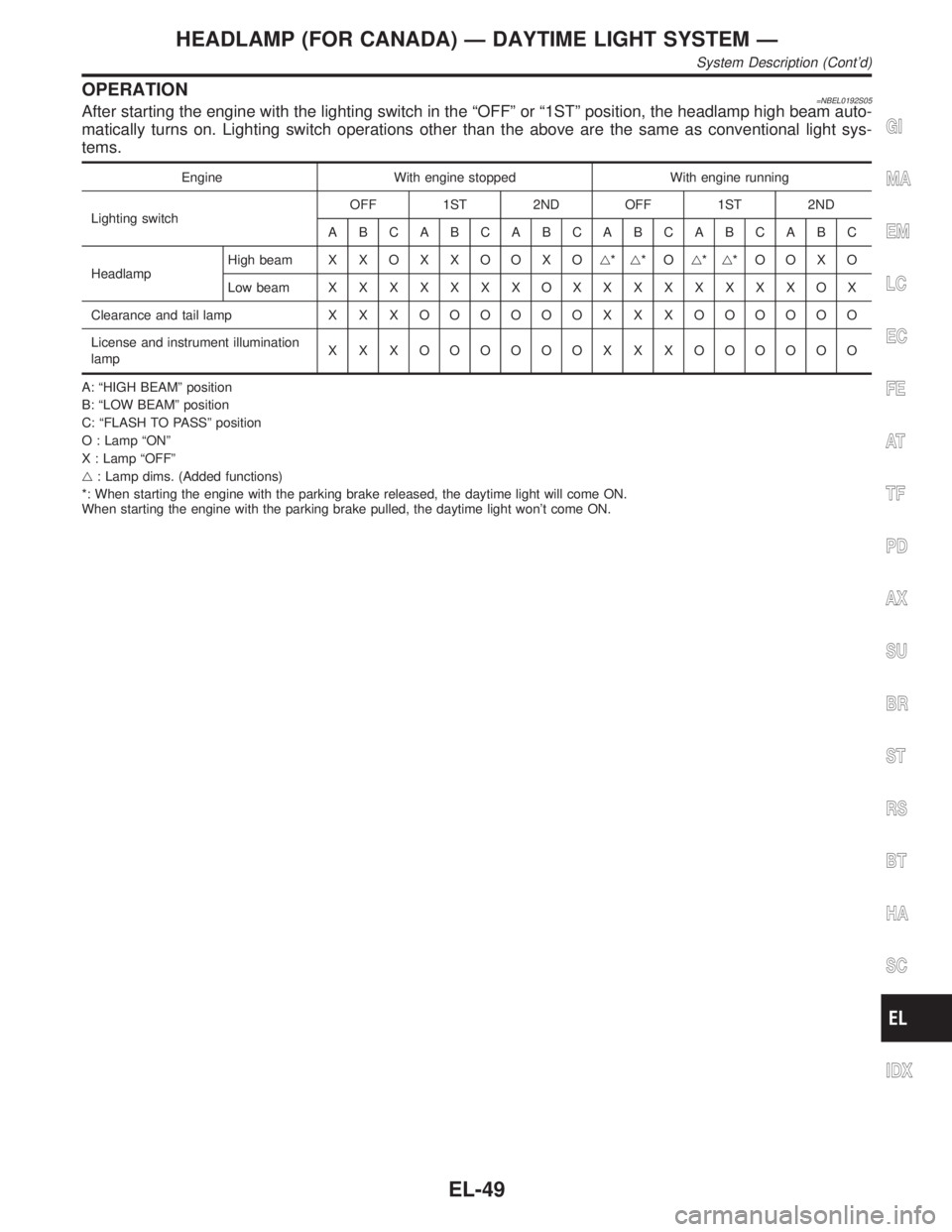
OPERATION=NBEL0192S05After starting the engine with the lighting switch in the ªOFFº or ª1STº position, the headlamp high beam auto-
matically turns on. Lighting switch operations other than the above are the same as conventional light sys-
tems.
Engine With engine stopped With engine running
Lighting switchOFF 1ST 2ND OFF 1ST 2ND
ABCABCABCABCABCABC
HeadlampHigh beam X X O X X O O X Og*g*Og*g*OOXO
Low beamXXXXXXXOXXXXXXXXOX
Clearance and tail lamp X X XOOOOOO X X X OOOOOO
License and instrument illumination
lampX X X OOOOOO X X X OOOOOO
A: ªHIGH BEAMº position
B: ªLOW BEAMº position
C: ªFLASH TO PASSº position
O : Lamp ªONº
X : Lamp ªOFFº
g: Lamp dims. (Added functions)
*: When starting the engine with the parking brake released, the daytime light will come ON.
When starting the engine with the parking brake pulled, the daytime light won't come ON.
GI
MA
EM
LC
EC
FE
AT
TF
PD
AX
SU
BR
ST
RS
BT
HA
SC
IDX
HEADLAMP (FOR CANADA) Ð DAYTIME LIGHT SYSTEM Ð
System Description (Cont'd)
EL-49
Page 1641 of 2395
NBEL0144
HeadlampNBEL0144S03
Item Wattage W
High/Low (Semi-sealed beam)55/35 (HB3/D2R)
Exterior LampNBEL0144S01
Item Wattage W
Front fog lamp55
Front turn signal lamp21
Parking lamp5
Rear combination lampTurn signal lamp 27
Stop/Tail lamp 21/5
Back-up lamp18
License plate lamp3.8
High-mounted stop lamp5
Interior LampNBEL0144S02
Item Wattage W
Interior lamp10
Spot lamp8
Luggage room lamp10
BULB SPECIFICATIONS
Headlamp
EL-456
Page 1704 of 2395
ComponentsNBEM0024
SEM584G
1. Rear oil seal retainer
2. Cylinder block
3. Knock sensor
4. Upper main bearing
5. Lower main bearing
6. Oil jet
7. Water drain plug (RH side)
8. Water drain plug (Water pump
side)9. Main bearing cap
10. Main bearing beam
11. Crankshaft
12. Pilot converter
13. Drive plate with signal plate
14. Drive plate reinforce plate
15. Oil ring
16. Piston pin17. Connecting rod bearing
18. Connecting rod
19. Piston
20. Top ring
21. 2nd ring
22. Baffle plate
23. Water drain plug (LH side)
GI
MA
LC
EC
FE
AT
TF
PD
AX
SU
BR
ST
RS
BT
HA
SC
EL
IDX
CYLINDER BLOCK
Components
EM-61
Page 1711 of 2395

SEM845E
2. Install main bearing cap and bearing beam to cylinder block.
Tighten all bolts in correct order.
3. Measure inner diameters ªAº of each main bearing.
AEM033
4. Measure outer diameters ªDmº of each crankshaft main jour-
nal.
5. Calculate main bearing clearance.
Main bearing clearance = A þ Dm
Standard: 0.035 - 0.045 mm (0.0014 - 0.0018 in)
Limit: 0.065 mm (0.0026 in)
IIf it exceeds the limit, replace bearing.
IIf clearance cannot be adjusted using any standard bearing
grade, grind crankshaft journal and use undersized bearing.
SEM964
a. When grinding crankshaft journal, confirm that ªLº dimension in
fillet roll is more than the specified limit.
ªLº: 0.1 mm (0.004 in)
b. Refer to SDS for grinding crankshaft and available service
parts.
SEM451G
6. If crankshaft or cylinder block is replaced with a new one,
select thickness of main bearings as follows:
a. Grade number of each cylinder block main journal is punched
on the respective cylinder block. These numbers are punched
in either Arabic or Alphabet. Refer to SDS, EM-81.
If measured diameter is out of grade punched, decide suitable
grade using table in SDS.
SEM452G
b. Grade number of each crankshaft main journal is punched on
the respective crankshaft. These numbers are punched in
either Arabic or Alphabet. Refer to SDS, EM-84.
If measured diameter is out of grade punched, decide suitable
grade using table in SDS.
c. Select main bearing with suitable thickness according to the
following table.
Refer to ªSDSº, EM-85, for available main bearings.
CYLINDER BLOCK
Inspection (Cont'd)
EM-68
Page 2172 of 2395

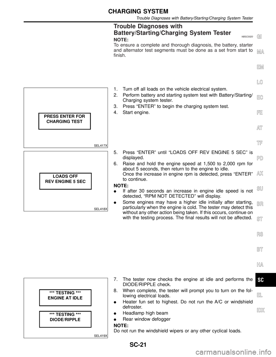
Trouble Diagnoses with
Battery/Starting/Charging System Tester
NBSC0020NOTE:
To ensure a complete and thorough diagnosis, the battery, starter
and alternator test segments must be done as a set from start to
finish.
SEL417X
1. Turn off all loads on the vehicle electrical system.
2. Perform battery and starting system test with Battery/Starting/
Charging system tester.
3. Press ªENTERº to begin the charging system test.
4. Start engine.
SEL418X
5. Press ªENTERº until ªLOADS OFF REV ENGINE 5 SECº is
displayed.
6. Raise and hold the engine speed at 1,500 to 2,000 rpm for
about 5 seconds, then return to the engine to idle.
Once the increase in engine rpm is detected, press ªENTERº
to continue.
NOTE:
IIf after 30 seconds an increase in engine idle speed is not
detected, ªRPM NOT DETECTEDº will display.
ISome engines may have a higher idle initially after starting,
particularly when the engine is cold. The tester may detect this
without any other action being taken. If this occurs, continue on
with the testing process. The final results will not be affected.
SEL419X
7. The tester now checks the engine at idle and performs the
DIODE/RIPPLE check.
8. When complete, the tester will prompt you to turn on the fol-
lowing electrical loads.
IHeater fun set to highest. Do not run the A/C or windshield
defroster.
IHeadlamp high beam
IRear window defogger
NOTE:
Do not run the windshield wipers or any other cyclical loads.
GI
MA
EM
LC
EC
FE
AT
TF
PD
AX
SU
BR
ST
RS
BT
HA
EL
IDX
CHARGING SYSTEM
Trouble Diagnoses with Battery/Starting/Charging System Tester
SC-21