2001 INFINITI QX4 belt
[x] Cancel search: beltPage 536 of 2395

ENGINE CONTROL SYSTEM
SECTION
EC
CONTENTS
TROUBLE DIAGNOSIS - INDEX....................................8
Alphabetical & P No. Index for DTC ...........................8
PRECAUTIONS.............................................................14
Supplemental Restraint System (SRS)²AIR
BAG²and²SEAT BELT PRE-TENSIONER².............14
Precautions for On Board Diagnostic (OBD)
System of Engine and A/T.........................................14
Engine Fuel & Emission Control System ..................15
Precautions ................................................................16
Wiring Diagrams and Trouble Diagnosis ...................17
PREPARATION.............................................................18
Special Service Tools ................................................18
Commercial Service Tools .........................................18
ENGINE AND EMISSION CONTROL OVERALL
SYSTEM.........................................................................20
Engine Control Component Parts Location ...............20
Circuit Diagram ..........................................................24
System Diagram ........................................................25
Vacuum Hose Drawing ..............................................26
System Chart .............................................................27
ENGINE AND EMISSION BASIC CONTROL
SYSTEM DESCRIPTION...............................................28
Multiport Fuel Injection (MFI) System .......................28
Electronic Ignition (EI) System ..................................30
Air Conditioning Cut Control ......................................31
Fuel Cut Control (at no load & high engine
speed) ........................................................................32
Evaporative Emission System ...................................32
Positive Crankcase Ventilation ..................................38
BASIC SERVICE PROCEDURE...................................39
Fuel Pressure Release ..............................................39
Fuel Pressure Check .................................................39
Fuel Pressure Regulator Check ................................40
Injector .......................................................................41
How to Check Idle Speed and Ignition Timing ..........42
Idle Speed/Ignition Timing/Idle Mixture Ratio
Adjustment .................................................................43
Idle Air Volume Learning ...........................................57ON BOARD DIAGNOSTIC SYSTEM
DESCRIPTION...............................................................59
Introduction ................................................................59
Two Trip Detection Logic ...........................................59
Emission-related Diagnostic Information ...................60
Malfunction Indicator Lamp (MIL) ..............................74
OBD System Operation Chart ...................................75
CONSULT-II ...............................................................81
Generic Scan Tool (GST) ..........................................95
TROUBLE DIAGNOSIS - INTRODUCTION..................97
Introduction ................................................................97
Work Flow ..................................................................99
TROUBLE DIAGNOSIS - BASIC INSPECTION.........101
Basic Inspection.......................................................101
TROUBLE DIAGNOSIS - GENERAL
DESCRIPTION............................................................. 116
DTC Inspection Priority Chart.................................. 116
Fail-safe Chart ......................................................... 117
Symptom Matrix Chart ............................................. 118
CONSULT-II Reference Value in Data Monitor
Mode ........................................................................122
Major Sensor Reference Graph in Data Monitor
Mode ........................................................................124
ECM Terminals and Reference Value .....................127
TROUBLE DIAGNOSIS - SPECIFICATION VALUE..136
Description ...............................................................136
Testing Condition .....................................................136
Inspection Procedure ...............................................136
Diagnostic Procedure ..............................................137
TROUBLE DIAGNOSIS FOR INTERMITTENT
INCIDENT.....................................................................140
Description ...............................................................140
Diagnostic Procedure ..............................................140
TROUBLE DIAGNOSIS FOR POWER SUPPLY........141
ECM Terminals and Reference Value .....................141
Main Power Supply and Ground Circuit ..................142
DTC P0100 MASS AIR FLOW SENSOR (MAFS)......150
Component Description ...........................................150
GI
MA
EM
LC
FE
AT
TF
PD
AX
SU
BR
ST
RS
BT
HA
SC
EL
IDX
Page 549 of 2395

Supplemental Restraint System (SRS) ªAIR
BAGº and ªSEAT BELT PRE-TENSIONERº
NBEC0002The Supplemental Restraint System such as ªAIR BAGº and ªSEAT BELT PRE-TENSIONERº used along with
a seat belt, helps to reduce the risk or severity of injury to the driver and front passenger for certain types of
collision. The SRS system composition which is available to INFINITI QX4 is as follows:
IFor a frontal collision
The Supplemental Restraint System consists of driver air bag module (located in the center of the steer-
ing wheel), front passenger air bag module (located on the instrument panel on passenger side), seat belt
pre-tensioners, a diagnosis sensor unit, warning lamp, wiring harness and spiral cable.
IFor a side collision
The Supplemental Restraint System consists of front side air bag module (located in the outer side of front
seat), satellite sensor, diagnosis sensor unit (one of components of air bags for a frontal collision), wiring
harness, warning lamp (one of components of air bags for a frontal collision).
Information necessary to service the system safely is included in theRS sectionof this Service Manual.
WARNING:
ITo avoid rendering the SRS inoperative, which could increase the risk of personal injury or death
in the event of a collision which would result in air bag inflation, all maintenance must be performed
by an authorized INFINITI dealer.
IImproper maintenance, including incorrect removal and installation of the SRS, can lead to per-
sonal injury caused by unintentional activation of the system. For removal of Spiral Cable and Air
Bag Module, see the RS section.
IDo not use electrical test equipment on any circuit related to the SRS unless instructed to in this
Service Manual. Spiral cable and wiring harnesses covered with yellow insulation tape either just
before the harness connectors or for the complete harness are related to the SRS.
Precautions for On Board Diagnostic (OBD)
System of Engine and A/T
NBEC0003The ECM has an on board diagnostic system. It will light up the malfunction indicator lamp (MIL) to warn the
driver of a malfunction causing emission deterioration.
CAUTION:
IBe sure to turn the ignition switch OFF and disconnect the negative battery terminal before any
repair or inspection work. The open/short circuit of related switches, sensors, solenoid valves, etc.
will cause the MIL to light up.
IBe sure to connect and lock the connectors securely after work. A loose (unlocked) connector will
cause the MIL to light up due to the open circuit. (Be sure the connector is free from water, grease,
dirt, bent terminals, etc.)
ICertain systems and components, especially those related to OBD, may use a new style slide-
locking type harness connector. For description and how to disconnect, refer to EL-6, ªHARNESS
CONNECTOR (SLIDE-LOCKING TYPE)º.
IBe sure to route and secure the harnesses properly after work. The interference of the harness with
a bracket, etc. may cause the MIL to light up due to the short circuit.
IBe sure to connect rubber tubes properly after work. A misconnected or disconnected rubber tube
may cause the MIL to light up due to the malfunction of the fuel injection system, etc.
IBe sure to erase the unnecessary malfunction information (repairs completed) from the ECM and
TCM (Transmission control module) before returning the vehicle to the customer.
PRECAUTIONS
Supplemental Restraint System (SRS) ªAIR BAGº and ªSEAT BELT PRE-TENSIONERº
EC-14
Page 1186 of 2395
ELECTRICAL SYSTEM
SECTION
EL
CONTENTS
PRECAUTIONS...............................................................4
Supplemental Restraint System (SRS)²AIR
BAG²and²SEAT BELT PRE-TENSIONER²...............4
Wiring Diagrams and Trouble Diagnosis .....................4
HARNESS CONNECTOR................................................5
Description ...................................................................5
STANDARDIZED RELAY................................................7
Description ...................................................................7
POWER SUPPLY ROUTING...........................................9
Schematic ....................................................................9
Wiring Diagram - POWER - ......................................10
Inspection...................................................................16
GROUND........................................................................17
Ground Distribution ....................................................17
COMBINATION SWITCH..............................................28
Check .........................................................................28
Replacement ..............................................................29
STEERING SWITCH......................................................30
Check .........................................................................30
HEADLAMP (FOR USA) - XENON TYPE -..................31
Component Parts and Harness Connector
Location .....................................................................31
System Description ....................................................31
Schematic ..................................................................35
Wiring Diagram - H/LAMP -.......................................36
Trouble Diagnoses.....................................................40
Bulb Replacement/Xenon Type .................................43
Aiming Adjustment .....................................................44
HEADLAMP (FOR CANADA) - DAYTIME LIGHT
SYSTEM -......................................................................46
Component Parts and Harness Connector
Location .....................................................................46
System Description ....................................................46
Schematic ..................................................................50
Wiring Diagram - DTRL - ...........................................51
Trouble Diagnoses.....................................................56
Bulb Replacement .....................................................57
Aiming Adjustment .....................................................58
HEADLAMP - HEADLAMP AIMING CONTROL -........59System Description ....................................................59
Wiring Diagram - H/AIM - ..........................................60
PARKING, LICENSE AND TAIL LAMPS.....................61
System Description ....................................................61
Schematic ..................................................................62
Wiring Diagram - TAIL/L - ..........................................63
Trouble Diagnoses.....................................................66
STOP LAMP..................................................................67
Wiring Diagram - STOP/L - .......................................67
BACK-UP LAMP............................................................69
Wiring Diagram - BACK/L - .......................................69
FRONT FOG LAMP.......................................................70
System Description ....................................................70
Wiring Diagram - F/FOG - .........................................72
Aiming Adjustment .....................................................74
TURN SIGNAL AND HAZARD WARNING LAMPS.....75
System Description ....................................................75
Wiring Diagram - TURN - ..........................................77
Trouble Diagnoses.....................................................79
Electrical Components Inspection .............................79
ILLUMINATION..............................................................80
System Description ....................................................80
Schematic ..................................................................82
Wiring Diagram - ILL - ...............................................83
INTERIOR, SPOT, VANITY MIRROR AND
LUGGAGE ROOM LAMPS...........................................88
System Description ....................................................88
Schematic ..................................................................90
Wiring Diagram - INT/L - ...........................................91
METERS AND GAUGES...............................................94
Component Parts and Harness Connector
Location .....................................................................94
System Description ....................................................94
Combination Meter ....................................................96
Schematic ..................................................................98
Wiring Diagram - METER - .......................................99
Meter/Gauge Operation and Odo/Trip Meter
Segment Check in Diagnosis Mode ........................100
Trouble Diagnoses...................................................101
GI
MA
EM
LC
EC
FE
AT
TF
PD
AX
SU
BR
ST
RS
BT
HA
SC
IDX
Page 1189 of 2395
Supplemental Restraint System (SRS) ªAIR
BAGº and ªSEAT BELT PRE-TENSIONERº
NBEL0001The Supplemental Restraint System such as ªAIR BAGº and ªSEAT BELT PRE-TENSIONERº used along with
a seat belt, helps to reduce the risk or severity of injury to the driver and front passenger for certain types of
collision. The SRS system composition which is available to INFINITI QX4 is as follows:
IFor a frontal collision
The Supplemental Restraint System consists of driver air bag module (located in the center of the steer-
ing wheel), front passenger air bag module (located on the instrument panel on passenger side), seat belt
pre-tensioners, a diagnosis sensor unit, warning lamp, wiring harness and spiral cable.
IFor a side collision
The Supplemental Restraint System consists of side air bag module (located in the outer side of front seat),
satellite sensor, diagnosis sensor unit (one of components of air bags for a frontal collision), wiring harness,
warning lamp (one of components of air bags for a frontal collision).
Information necessary to service the system safely is included in theRS sectionof this Service Manual.
WARNING:
ITo avoid rendering the SRS inoperative, which could increase the risk of personal injury or death
in the event of a collision which would result in air bag inflation, all maintenance must be performed
by an authorized INFINITI dealer.
IImproper maintenance, including incorrect removal and installation of the SRS, can lead to per-
sonal injury caused by unintentional activation of the system. For removal of Spiral Cable and Air
Bag Module, see the RS section.
IDo not use electrical test equipment on any circuit related to the SRS unless instructed to in this
Service Manual. Spiral cable and wiring harnesses covered with yellow insulation tape either just
before the harness connectors or for the complete harness are related to the SRS.
Wiring Diagrams and Trouble DiagnosisNBEL0002When you read wiring diagrams, refer to the following:
IGI-11, ªHOW TO READ WIRING DIAGRAMSº
IEL-9, ªPOWER SUPPLY ROUTINGº for power distribution circuit
When you perform trouble diagnosis, refer to the following:
IGI-35, ªHOW TO FOLLOW TEST GROUPS IN TROUBLE DIAGNOSESº
IGI-24, ªHOW TO PERFORM EFFICIENT DIAGNOSIS FOR AN ELECTRICAL INCIDENTº
Check for any Service bulletins before servicing the vehicle.
PRECAUTIONS
Supplemental Restraint System (SRS) ªAIR BAGº and ªSEAT BELT PRE-TENSIONERº
EL-4
Page 1311 of 2395
Ito smart entrance control unit terminal 29.
Front door switch LH terminal 2 is grounded through body grounds B11, B22 and D210.
SEAT BELT WARNING CHIMENBEL0053S03With ignition switch turned ON and seat belt unfastened (seat belt switch ON), warning chime will sound for
approximately 6 seconds.
Ground is supplied
Ifrom seat belt switch terminal 1
Ito smart entrance control unit terminal 22.
Seat belt switch terminal 2 is grounded through body grounds B11, B22 and D210.
WARNING CHIME
System Description (Cont'd)
EL-126
Page 1314 of 2395
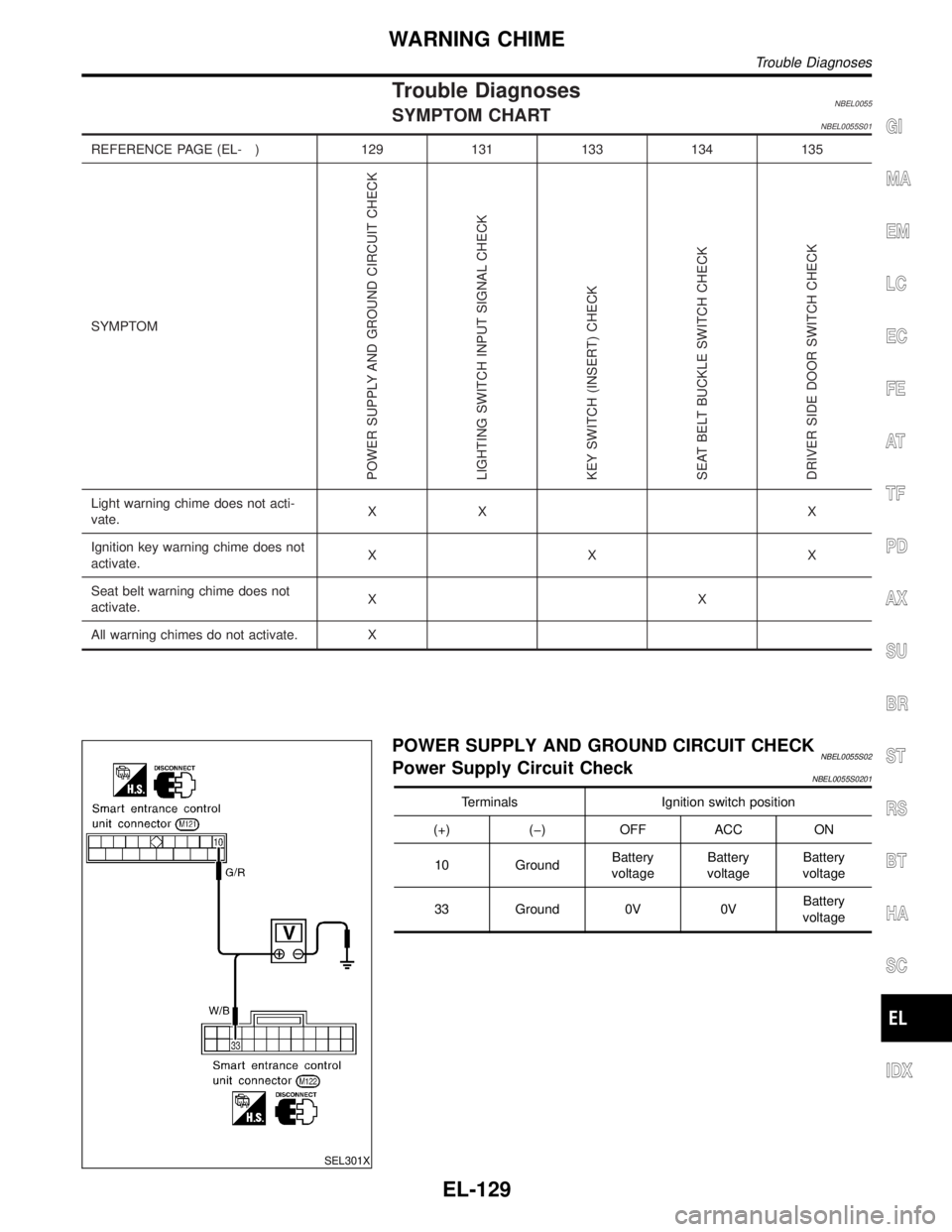
Trouble DiagnosesNBEL0055SYMPTOM CHARTNBEL0055S01
REFERENCE PAGE (EL- ) 129 131 133 134 135
SYMPTOM
POWER SUPPLY AND GROUND CIRCUIT CHECK
LIGHTING SWITCH INPUT SIGNAL CHECK
KEY SWITCH (INSERT) CHECK
SEAT BELT BUCKLE SWITCH CHECK
DRIVER SIDE DOOR SWITCH CHECK
Light warning chime does not acti-
vate.XX X
Ignition key warning chime does not
activate.XXX
Seat belt warning chime does not
activate.XX
All warning chimes do not activate. X
SEL301X
POWER SUPPLY AND GROUND CIRCUIT CHECKNBEL0055S02Power Supply Circuit CheckNBEL0055S0201
Terminals Ignition switch position
(+) (þ) OFF ACC ON
10 GroundBattery
voltageBattery
voltageBattery
voltage
33 Ground 0V 0VBattery
voltage
GI
MA
EM
LC
EC
FE
AT
TF
PD
AX
SU
BR
ST
RS
BT
HA
SC
IDX
WARNING CHIME
Trouble Diagnoses
EL-129
Page 1319 of 2395

SEAT BELT BUCKLE SWITCH CHECK=NBEL0055S05
1 CHECK SEAT BELT BUCKLE SWITCH INPUT SIGNAL
1. Turn ignition switch ªONº.
2. Check voltage between smart entrance control unit terminal 22 and ground.
SEL380X
OK or NG
OK©Seat belt buckle switch is OK.
NG©GO TO 2.
2 CHECK SEAT BELT BUCKLE SWITCH
Check continuity between terminals 1 and 2 when seat belt is fastened and unfastened.
SEL381X
OK or NG
OK©Check the following.
ISeat belt buckle switch ground circuit
IHarness for open or short between smart entrance control unit and seat belt buckle
switch
NG©Replace seat belt buckle switch.
WARNING CHIME
Trouble Diagnoses (Cont'd)
EL-134
Page 1504 of 2395
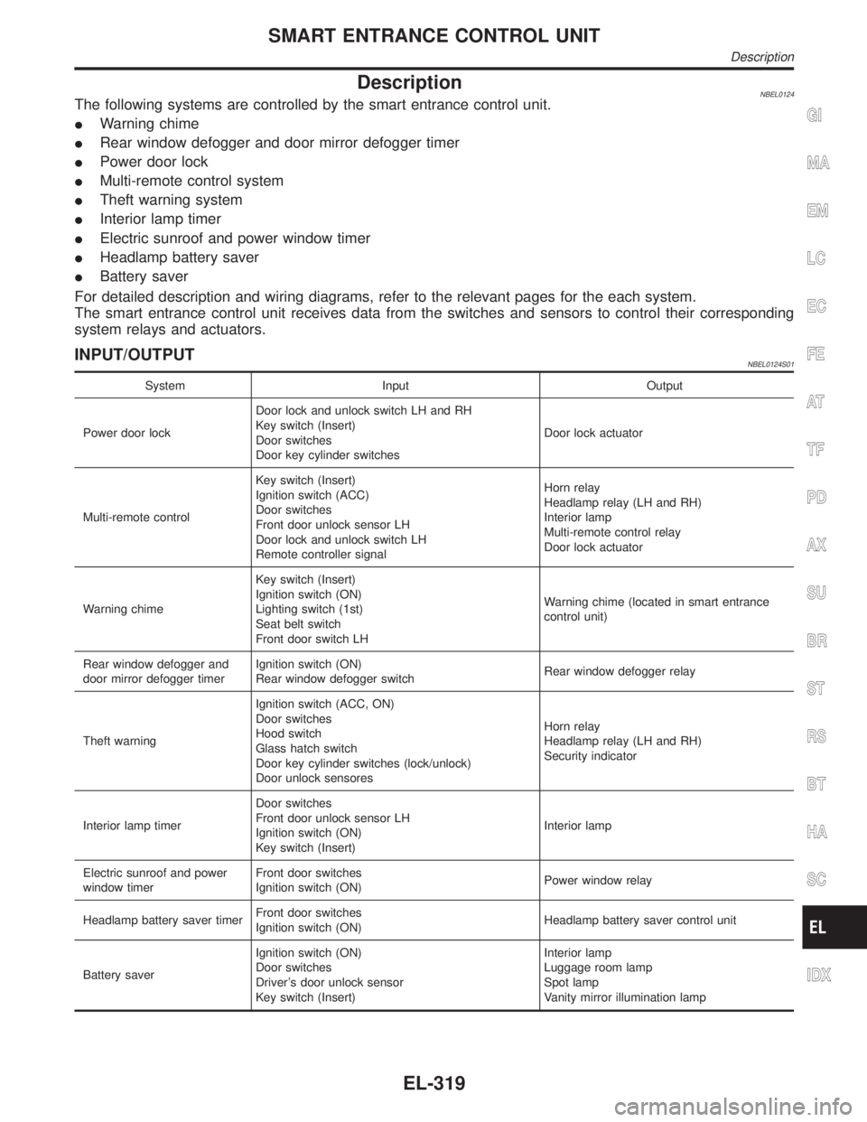
DescriptionNBEL0124The following systems are controlled by the smart entrance control unit.
IWarning chime
IRear window defogger and door mirror defogger timer
IPower door lock
IMulti-remote control system
ITheft warning system
IInterior lamp timer
IElectric sunroof and power window timer
IHeadlamp battery saver
IBattery saver
For detailed description and wiring diagrams, refer to the relevant pages for the each system.
The smart entrance control unit receives data from the switches and sensors to control their corresponding
system relays and actuators.
INPUT/OUTPUTNBEL0124S01
System Input Output
Power door lockDoor lock and unlock switch LH and RH
Key switch (Insert)
Door switches
Door key cylinder switchesDoor lock actuator
Multi-remote controlKey switch (Insert)
Ignition switch (ACC)
Door switches
Front door unlock sensor LH
Door lock and unlock switch LH
Remote controller signalHorn relay
Headlamp relay (LH and RH)
Interior lamp
Multi-remote control relay
Door lock actuator
Warning chimeKey switch (Insert)
Ignition switch (ON)
Lighting switch (1st)
Seat belt switch
Front door switch LHWarning chime (located in smart entrance
control unit)
Rear window defogger and
door mirror defogger timerIgnition switch (ON)
Rear window defogger switchRear window defogger relay
Theft warningIgnition switch (ACC, ON)
Door switches
Hood switch
Glass hatch switch
Door key cylinder switches (lock/unlock)
Door unlock sensoresHorn relay
Headlamp relay (LH and RH)
Security indicator
Interior lamp timerDoor switches
Front door unlock sensor LH
Ignition switch (ON)
Key switch (Insert)Interior lamp
Electric sunroof and power
window timerFront door switches
Ignition switch (ON)Power window relay
Headlamp battery saver timerFront door switches
Ignition switch (ON)Headlamp battery saver control unit
Battery saverIgnition switch (ON)
Door switches
Driver's door unlock sensor
Key switch (Insert)Interior lamp
Luggage room lamp
Spot lamp
Vanity mirror illumination lamp
GI
MA
EM
LC
EC
FE
AT
TF
PD
AX
SU
BR
ST
RS
BT
HA
SC
IDX
SMART ENTRANCE CONTROL UNIT
Description
EL-319