2001 INFINITI QX4 automatic transmission
[x] Cancel search: automatic transmissionPage 361 of 2395

General SpecificationsNBAT0160
Applied modelVQ35DE engine
2WD 4WD
Automatic transmission model RE4R01A
Transmission model code number 4EX16 4EX17
Stall torque ratio2.0:1
Transmission gear ratio1st 2.785
2nd 1.545
Top 1.000
OD 0.694
Reverse 2.272
Recommended fluidNissan Matic ªDº (Continental U.S. and Alaska) or Genuine Nissan Automatic Trans-
mission Fluid (Canada)*1
Fluid capacity8.5(9 US qt, 7-1/2 Imp qt)
*1: Refer to MA-11, ªFluids and Lubricantsº.
Shift ScheduleNBAT0178VEHICLE SPEED WHEN SHIFTING GEARS THROTTLE POSITIONNBAT0178S01
Throttle positionVehicle speed km/h (MPH)
D
1,D2D2,D3D3,D4D4,D3D3,D2D2,D112,11
Full throttle55-59
(34 - 37)105 - 113
(65 - 70)174 - 184
(108 - 114)170 - 180
(106 - 112)102 - 110
(63 - 68)43-47
(27 - 29)43-47
(27 - 29)
Half throttle37-41
(23 - 25)71-79
(44 - 49)129 - 139
(80 - 86)81-91
(50 - 57)33-41
(21 - 25)12-16
(7 - 10)43-47
(27 - 29)
VEHICLE SPEED WHEN PERFORMING AND RELEASING LOCK-UPNBAT0178S02
Throttle positionOverdrive control switch [Shift posi-
tion]Vehicle speed km/h (MPH)
Lock-up ªONº Lock-up ªOFFº
Full throttleON [D
4] 174 - 184 (108 - 114) 170 - 180 (106 - 112)
OFF [D
3] 104 - 114 (65 - 71) 101 - 111 (63 - 69)
Half throttleON [D
4] 151 - 161 (94 - 100) 106 - 116 (66 - 72)
OFF [D
3] 85-95(53-59) 82-92(51-57)
Stall RevolutionNBAT0163
Stall revolution rpm2,440 - 2,640
Line PressureNBAT0164
Engine speed
rpmLine pressure kPa (kg/cm2, psi)
D, 2 and 1 positions R position
Idle 422 - 461 (4.3 - 4.7, 61 - 67) 667 - 706 (6.8 - 7.2, 97 - 102)
Stall 1,020 - 1,098 (10.4 - 11.2, 148 - 159) 1,422 - 1,500 (14.5 - 15.3, 206 - 218)
SERVICE DATA AND SPECIFICATIONS (SDS)
General Specifications
AT-356
Page 579 of 2395
IAir intake system
(Oil filler cap, oil level gauge, etc.)
IFuel pressure
IEngine compression
IThrottle valve
IEvaporative emission system
2) On air conditioner equipped models, checks should be carried out while the air conditioner is ªOFFº.
3) On automatic transmission equipped models, when checking idle rpm, ignition timing and mixture ratio,
checks should be carried out while shift lever is in ªNº position.
4) When measuring ªCOº percentage, insert probe more than 40 cm (15.7 in) into tail pipe.
5) Turn off headlamps, heater blower, rear defogger.
6) Keep front wheels pointed straight ahead.
7) Make the check after the cooling fan has stopped.
BASIC SERVICE PROCEDURE
Idle Speed/Ignition Timing/Idle Mixture Ratio Adjustment (Cont'd)
EC-44
Page 1138 of 2395
Component DescriptionNBEC0361The malfunction information related to A/T (Automatic Transmission) is transferred through the line (circuit)
from TCM (Transmission control module) to ECM. Therefore, be sure to erase the malfunction information such
as DTC not only in TCM (Transmission control module) but also ECM after the A/T related repair.
On Board Diagnosis LogicNBEC0363Malfunction is detected when an incorrect signal from TCM (Trans-
mission control module) is sent to ECM.
Possible CauseNBEC0594IHarness or connectors
[The communication line circuit between ECM and TCM
(Transmission control module) is open or shorted.]
IDead (Weak) battery
ITCM (Transmission control module)
SEF058Y
DTC Confirmation ProcedureNBEC0364NOTE:
If ªDTC Confirmation Procedureº has been previously conducted,
always turn ignition switch ªOFFº and wait at least 10 seconds
before conducting the next test.
TESTING CONDITION:
Before performing the following procedure, confirm that bat-
tery voltage is more than 10.5V at idle.
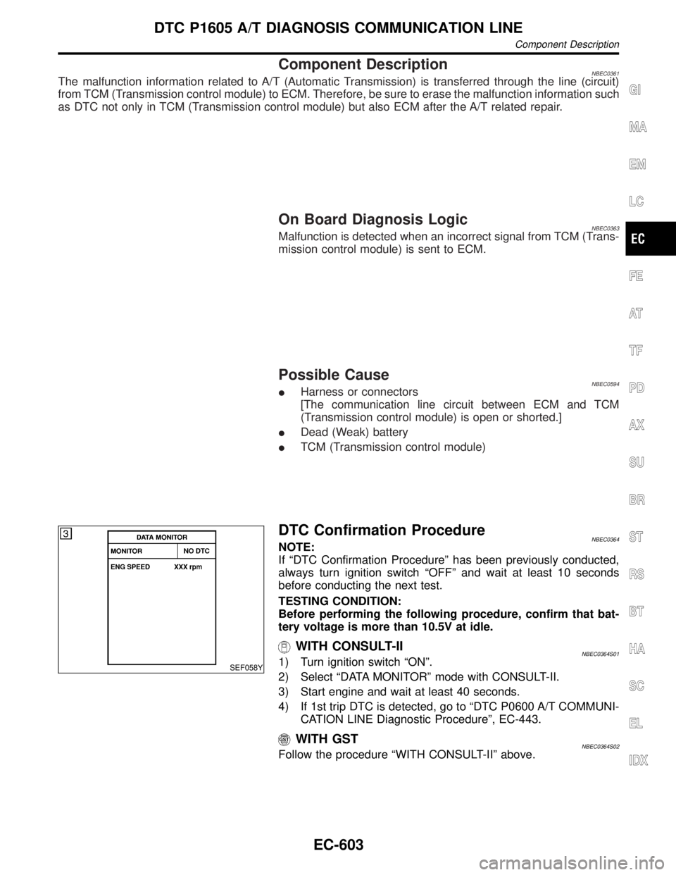
WITH CONSULT-IINBEC0364S011) Turn ignition switch ªONº.
2) Select ªDATA MONITORº mode with CONSULT-II.
3) Start engine and wait at least 40 seconds.
4) If 1st trip DTC is detected, go to ªDTC P0600 A/T COMMUNI-
CATION LINE Diagnostic Procedureº, EC-443.
WITH GSTNBEC0364S02Follow the procedure ªWITH CONSULT-IIº above.
GI
MA
EM
LC
FE
AT
TF
PD
AX
SU
BR
ST
RS
BT
HA
SC
EL
IDX
DTC P1605 A/T DIAGNOSIS COMMUNICATION LINE
Component Description
EC-603
Page 1407 of 2395
System DescriptionNBEL0216Refer to Owner's Manual for ASCD operating instructions.
POWER SUPPLY AND GROUNDNBEL0216S01Power is supplied at all times:
Ithrough 10A fuse [No. 14, located in the fuse block (J/B)]
Ito the stop lamp switch terminal 1, and
Ithrough 7.5A fuse (No. 52, located in fuse and fusible link box)
Ito the horn relay terminals 1 and 3.
When ignition switch is in the ON or START position, power is supplied:
Ithrough 7.5A fuse [No. 11, located in the fuse block (J/B)]
Ito ASCD brake switch terminal 1 and
Ito ASCD control unit terminal 5,
Ithrough 10A fuse [No. 18, located in the fuse block (J/B)]
Ito park/neutral position relay terminal 1,
Ithrough 10A fuse [No. 8, located in the fuse block (J/B)]
Ito combination meter terminal 66, and
When park/neutral position switch is in the P or N position, ground is supplied:
Ito park/neutral position relay terminal 2
Ithrough park/neutral position switch and body grounds B55 and B75.
When ASCD main switch is depressed (ON), ground is supplied:
Ito ASCD control unit terminal 9
Ifrom ASCD steering switch terminal 4
Ito ASCD steering switch terminal 5
Ithrough body grounds M4, M66 and M147
then ASCD control unit holds CRUISE condition and illuminates CRUISE indicator.
Ground is supplied:
Ifrom ASCD control unit terminal 15
Ito combination meter terminal 46.
OPERATIONNBEL0216S02Set OperationNBEL0216S0201To activate the ASCD, all following conditions must exist.
IGround supply to ASCD control unit terminal 9 (Main switch is in ON position.)
IPower supply to ASCD control unit terminal 8 (Brake pedal is released and A/T selector lever is in other
than P and N position.)
IVehicle speed is between 40 km/h (25 MPH) and 144 km/h (89 MPH). (Signal from combination meter)
When the SET/COAST switch is depressed, power is supplied:
Ifrom ASCD steering switch terminal 2
Ito ASCD control unit terminal 11.
And then ASCD pump is activated to control throttle wire and ASCD control unit supply ground
Ito combination meter terminals 51 to illuminate SET indicator.
A/T Overdrive Control during Cruise Control DrivingNBEL0216S0202When the vehicle speed is approximately 3 km/h (2 MPH) below set speed, a signal is sent
Ifrom ASCD control unit terminal 10
Ito TCM (transmission control module) terminal 24.
When this occurs, the TCM (transmission control module) cancels overdrive.
After vehicle speed is approximately 1 km/h (1 MPH) below set speed, overdrive is reactivated.
ASCD Shifting ControlNBEL0216S0203During ASCD cruise, ASCD control unit controls A/T shifting to avoid uncomfortable shifting.
This is used to control the signals below.
IThrottle position sensor from ECM
AUTOMATIC SPEED CONTROL DEVICE (ASCD)
System Description
EL-222
Page 1540 of 2395
greatly depending on the cellular network and cellular signal
strength. The system resets to ready when the system com-
pletes the dialing attempts. The vehicle owner can press the
button again if he or she still needs to contact the Communi-
cator Response Center.
IINFINITI Communicator automatically redials if communication
between the vehicle owner and Communicator Response Cen-
ter is lost for some reason.
IThe only way for a transmission to be officially terminated is for
the Communicator Response Center to send an end transmis-
sion signal, which turns off the indicator in the switch. (Com-
munication with Communicator Response Center can not be
terminated by the occupant.)
IIf the vehicle owner start the engine during a call, the conver-
sation may be interrupted. When this happens the system may
try to resume transmission once after the engine has been
started.
SEL526V
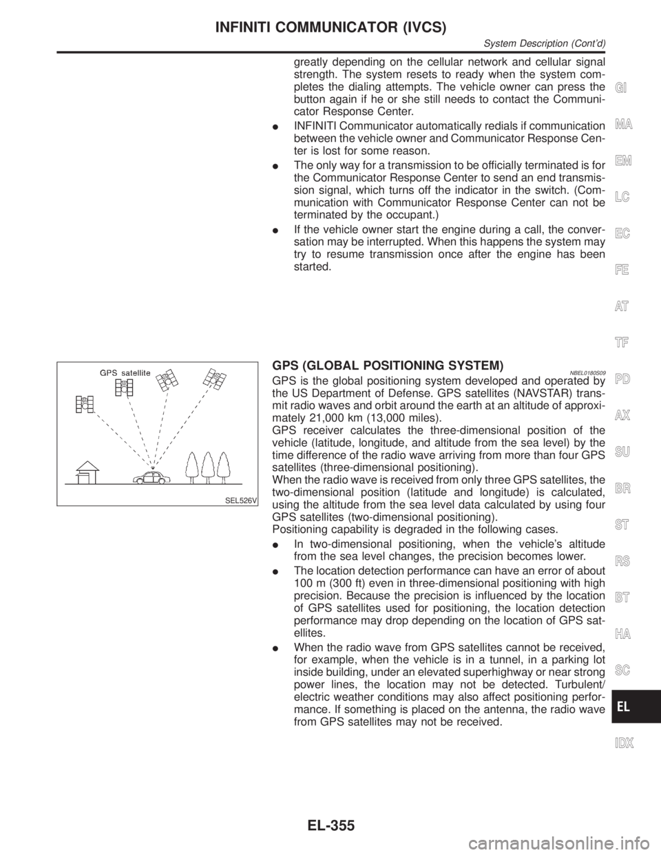
GPS (GLOBAL POSITIONING SYSTEM)NBEL0180S09GPS is the global positioning system developed and operated by
the US Department of Defense. GPS satellites (NAVSTAR) trans-
mit radio waves and orbit around the earth at an altitude of approxi-
mately 21,000 km (13,000 miles).
GPS receiver calculates the three-dimensional position of the
vehicle (latitude, longitude, and altitude from the sea level) by the
time difference of the radio wave arriving from more than four GPS
satellites (three-dimensional positioning).
When the radio wave is received from only three GPS satellites, the
two-dimensional position (latitude and longitude) is calculated,
using the altitude from the sea level data calculated by using four
GPS satellites (two-dimensional positioning).
Positioning capability is degraded in the following cases.
IIn two-dimensional positioning, when the vehicle's altitude
from the sea level changes, the precision becomes lower.
IThe location detection performance can have an error of about
100 m (300 ft) even in three-dimensional positioning with high
precision. Because the precision is influenced by the location
of GPS satellites used for positioning, the location detection
performance may drop depending on the location of GPS sat-
ellites.
IWhen the radio wave from GPS satellites cannot be received,
for example, when the vehicle is in a tunnel, in a parking lot
inside building, under an elevated superhighway or near strong
power lines, the location may not be detected. Turbulent/
electric weather conditions may also affect positioning perfor-
mance. If something is placed on the antenna, the radio wave
from GPS satellites may not be received.
GI
MA
EM
LC
EC
FE
AT
TF
PD
AX
SU
BR
ST
RS
BT
HA
SC
IDX
INFINITI COMMUNICATOR (IVCS)
System Description (Cont'd)
EL-355
Page 1746 of 2395
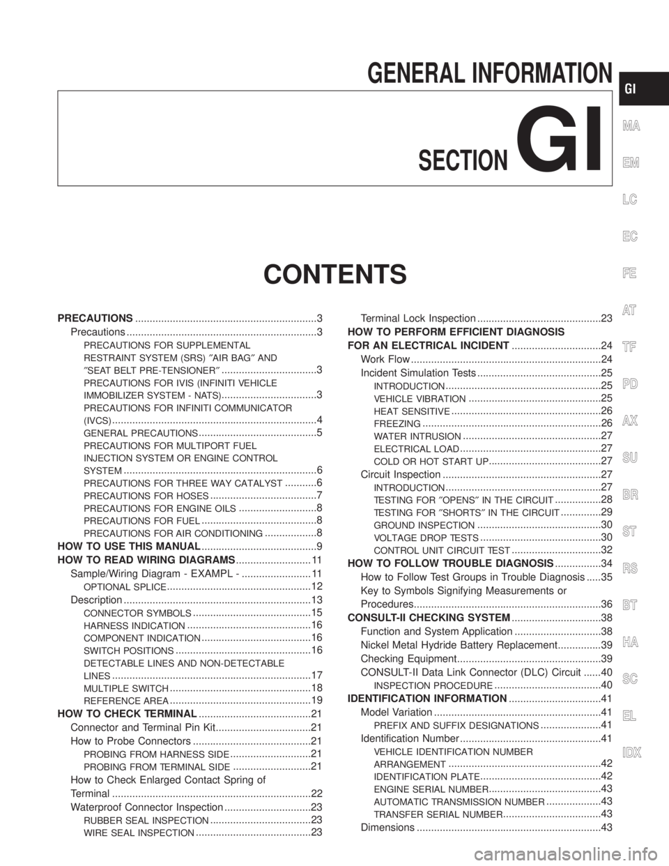
GENERAL INFORMATION
SECTION
GI
CONTENTS
PRECAUTIONS...............................................................3
Precautions ..................................................................3
PRECAUTIONS FOR SUPPLEMENTAL
RESTRAINT SYSTEM (SRS)²AIR BAG²AND
²SEAT BELT PRE-TENSIONER²
.................................3
PRECAUTIONS FOR IVIS (INFINITI VEHICLE
IMMOBILIZER SYSTEM - NATS)
.................................3
PRECAUTIONS FOR INFINITI COMMUNICATOR
(IVCS)
.......................................................................4
GENERAL PRECAUTIONS.........................................5
PRECAUTIONS FOR MULTIPORT FUEL
INJECTION SYSTEM OR ENGINE CONTROL
SYSTEM
...................................................................6
PRECAUTIONS FOR THREE WAY CATALYST...........6
PRECAUTIONS FOR HOSES.....................................7
PRECAUTIONS FOR ENGINE OILS...........................8
PRECAUTIONS FOR FUEL........................................8
PRECAUTIONS FOR AIR CONDITIONING..................8
HOW TO USE THIS MANUAL........................................9
HOW TO READ WIRING DIAGRAMS.......................... 11
Sample/Wiring Diagram - EXAMPL - ........................ 11
OPTIONAL SPLICE..................................................12
Description .................................................................13
CONNECTOR SYMBOLS.........................................15
HARNESS INDICATION...........................................16
COMPONENT INDICATION......................................16
SWITCH POSITIONS...............................................16
DETECTABLE LINES AND NON-DETECTABLE
LINES
.....................................................................17
MULTIPLE SWITCH.................................................18
REFERENCE AREA.................................................19
HOW TO CHECK TERMINAL.......................................21
Connector and Terminal Pin Kit.................................21
How to Probe Connectors .........................................21
PROBING FROM HARNESS SIDE............................21
PROBING FROM TERMINAL SIDE...........................21
How to Check Enlarged Contact Spring of
Terminal .....................................................................22
Waterproof Connector Inspection ..............................23
RUBBER SEAL INSPECTION...................................23
WIRE SEAL INSPECTION........................................23Terminal Lock Inspection ...........................................23
HOW TO PERFORM EFFICIENT DIAGNOSIS
FOR AN ELECTRICAL INCIDENT...............................24
Work Flow ..................................................................24
Incident Simulation Tests ...........................................25
INTRODUCTION......................................................25
VEHICLE VIBRATION..............................................25
HEAT SENSITIVE....................................................26
FREEZING..............................................................26
WATER INTRUSION................................................27
ELECTRICAL LOAD.................................................27
COLD OR HOT START UP.......................................27
Circuit Inspection .......................................................27
INTRODUCTION......................................................27
TESTING FOR²OPENS²IN THE CIRCUIT................28
TESTING FOR²SHORTS²IN THE CIRCUIT..............29
GROUND INSPECTION...........................................30
VOLTAGE DROP TESTS..........................................30
CONTROL UNIT CIRCUIT TEST...............................32
HOW TO FOLLOW TROUBLE DIAGNOSIS................34
How to Follow Test Groups in Trouble Diagnosis .....35
Key to Symbols Signifying Measurements or
Procedures.................................................................36
CONSULT-II CHECKING SYSTEM...............................38
Function and System Application ..............................38
Nickel Metal Hydride Battery Replacement...............39
Checking Equipment..................................................39
CONSULT-II Data Link Connector (DLC) Circuit ......40
INSPECTION PROCEDURE.....................................40
IDENTIFICATION INFORMATION................................41
Model Variation ..........................................................41
PREFIX AND SUFFIX DESIGNATIONS.....................41
Identification Number .................................................41
VEHICLE IDENTIFICATION NUMBER
ARRANGEMENT
.....................................................42
IDENTIFICATION PLATE..........................................42
ENGINE SERIAL NUMBER.......................................43
AUTOMATIC TRANSMISSION NUMBER...................43
TRANSFER SERIAL NUMBER..................................43
Dimensions ................................................................43
MA
EM
LC
EC
FE
AT
TF
PD
AX
SU
BR
ST
RS
BT
HA
SC
EL
IDX
Page 1754 of 2395
NBGI0002
IThe captionsWARNINGandCAUTIONwarn you of steps that must be followed to prevent personal injury
and/or damage to some part of the vehicle.
WARNINGindicates the possibility of personal injury if instructions are not followed.
CAUTIONindicates the possibility of component damage if instructions are not followed.
BOLD TYPED STATEMENTSexceptWARNINGandCAUTIONgive you helpful information.
IALPHABETICAL INDEXis provided at the end of this manual so that you can rapidly find the item and
page you are searching for.
IA QUICK REFERENCE INDEX, a black tab (e.g.
) is provided on the first page. You can quickly find
the first page of each section by mating it to the section's black tab.
ITHE CONTENTSare listed on the first page of each section.
ITHE TITLEis indicated on the upper portion of each page and shows the part or system.
ITHE PAGE NUMBERof each section consists of two letters which designate the particular section and a
number (e.g. ªBR-5º).
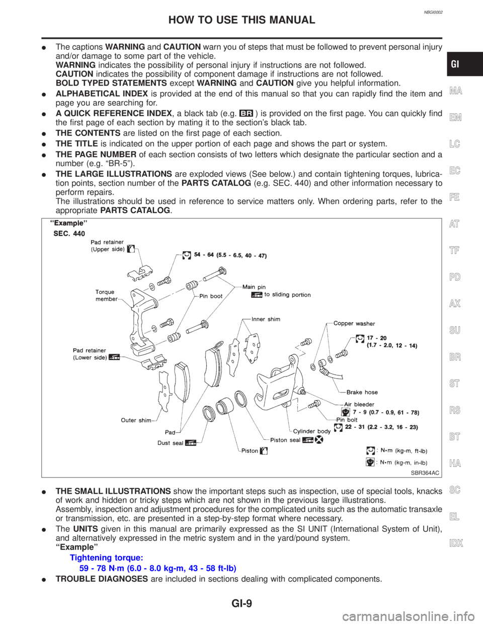
ITHE LARGE ILLUSTRATIONSare exploded views (See below.) and contain tightening torques, lubrica-
tion points, section number of thePARTS CATALOG(e.g. SEC. 440) and other information necessary to
perform repairs.
The illustrations should be used in reference to service matters only. When ordering parts, refer to the
appropriatePARTS CATALOG.
SBR364AC
ITHE SMALL ILLUSTRATIONSshow the important steps such as inspection, use of special tools, knacks
of work and hidden or tricky steps which are not shown in the previous large illustrations.
Assembly, inspection and adjustment procedures for the complicated units such as the automatic transaxle
or transmission, etc. are presented in a step-by-step format where necessary.
ITheUNITSgiven in this manual are primarily expressed as the SI UNIT (International System of Unit),
and alternatively expressed in the metric system and in the yard/pound system.
ªExampleº
Tightening torque:
59 - 78 N´m (6.0 - 8.0 kg-m, 43 - 58 ft-lb)
ITROUBLE DIAGNOSESare included in sections dealing with complicated components.
MA
EM
LC
EC
FE
AT
TF
PD
AX
SU
BR
ST
RS
BT
HA
SC
EL
IDX
HOW TO USE THIS MANUAL
GI-9
Page 1755 of 2395
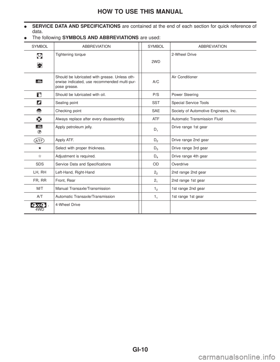
ISERVICE DATA AND SPECIFICATIONSare contained at the end of each section for quick reference of
data.
IThe followingSYMBOLS AND ABBREVIATIONSare used:
SYMBOL ABBREVIATION SYMBOL ABBREVIATION
Tightening torque
2WD2-Wheel Drive
Should be lubricated with grease. Unless oth-
erwise indicated, use recommended multi-pur-
pose grease.A/CAir Conditioner
Should be lubricated with oil. P/S Power Steering
Sealing point SST Special Service Tools
Checking point SAE Society of Automotive Engineers, Inc.
Always replace after every disassembly. ATF Automatic Transmission Fluid
qP
Apply petroleum jelly.
D1Drive range 1st gear
Apply ATF. D2Drive range 2nd gear
HSelect with proper thickness. D
3Drive range 3rd gear
IAdjustment is required. D
4Drive range 4th gear
SDS Service Data and Specifications OD Overdrive
LH, RH Left-Hand, Right-Hand 2
22nd range 2nd gear
FR, RR Front, Rear 2
12nd range 1st gear
M/T Manual Transaxle/Transmission 1
21st range 2nd gear
A/T Automatic Transaxle/Transmission 1
11st range 1st gear
,
4WD4-Wheel Drive
HOW TO USE THIS MANUAL
GI-10