2001 INFINITI QX4 air conditioning
[x] Cancel search: air conditioningPage 1802 of 2395
ISuggest the customer return the vehicle to the location of previous service where the contamination may
have occurred.
IIf you choose to perform the repair, recover the refrigerant using onlydedicated equipment and con-
tainers. Do not recover contaminated refrigerant into your existing service equipment.If your facil-
ity does not have dedicated recovery equipment, you may contact a local refrigerant product retailer for
available service. This refrigerant must be disposed of in accordance with all federal and local regulations.
In addition, replacement of all refrigerant system components on the vehicle is recommended.
IIf the vehicle is within the warranty period, the air conditioner warranty is void. Please contact Nissan
Customer Affairs for further assistance.
General Refrigerant PrecautionsNBHA0003WARNING:
IDo not release refrigerant into the air. Use approved recovery/recycling equipment to capture the
refrigerant every time an air conditioning system is discharged.
IAlways wear eye and hand protection (goggles and gloves) when working with any refrigerant or
air conditioning system.
IDo not store or heat refrigerant containers above 52ÉC (125ÉF).
IDo not heat a refrigerant container with an open flame; if container warming is required, place the
bottom of the container in a warm pail of water.
IDo not intentionally drop, puncture, or incinerate refrigerant containers.
IKeep refrigerant away from open flames: poisonous gas will be produced if refrigerant burns.
IRefrigerant will displace oxygen, therefore be certain to work in well ventilated areas to prevent
suffocation.
IDo not pressure test or leak test HFC-134a (R-134a) service equipment and/or vehicle air condi-
tioning systems with compressed air during repair. Some mixtures of air and R-134a have been
shown to be combustible at elevated pressures. These mixtures, if ignited, may cause injury or
property damage. Additional health and safety information may be obtained from refrigerant manu-
facturers.
Precautions for Leak Detection DyeNBHA0111IThe A/C system contains a fluorescent leak detection dye used for locating refrigerant leaks. An ultravio-
let (UV) lamp is required to illuminate the dye when inspecting for leaks.
IAlways wear fluorescence enhancing UV safety glasses to protect your eyes and enhance the visibility of
the fluorescent dye.
IThe fluorescent dye leak detector is not a replacement for an electronic refrigerant leak detector. The
fluorescent dye leak detector should be used in conjunction with an electronic refrigerant leak detector to
(J-41995) pin-point refrigerant leaks.
IFor your safety and your Customer's satisfaction, read and follow all manufacture's operating instructions
and precautions prior to performing the work.
IA compressor shaft seal should not be repaired because of dye seepage. The compressor shaft seal
should only be repaired after confirming the leak with an electronic refrigerant leak detector (J-41995).
IAlways remove and dye from the leak area after repairs are complete to avoid a misdiagnosis during a
future service.
IDo not allow dye to come into contact with painted body panels or interior components. If dye is spilled,
clean immediately with the approved dye cleaner. Fluorescent dye left on a surface for an extended period
of time cannot be removed.
IDo not spray the fluorescent dye cleaning agent on hot surfaces (engine exhaust manifold, etc.).
IDo not use more than one refrigerant dye bottle (1/4 ounce /7.4 cc) per A/C system.
ILeak detection dyes for R-134a and R12 A/C systems are different. Do not use R-134a leak detection dye
in R-12 A/C system or R-12 leak detector dye in R-134a A/C systems or A/C system damage may result.
IThe fluorescent properties of the dye will remain for over three (3) years unless a compressor failure
occurs.
GI
MA
EM
LC
EC
FE
AT
TF
PD
AX
SU
BR
ST
RS
BT
SC
EL
IDX
PRECAUTIONS
Precautions for Working with HFC-134a (R-134a) (Cont'd)
HA-3
Page 1814 of 2395
V-6 Variable Displacement Compressor
GENERAL INFORMATION=NBHA00861. The V-6 variable compressor differs from previous units. The vent temperatures of the V-6 variable com-
press do not drop too far below 5ÉC (41ÉF) when:
Ievaporator intake air temperature is less than 20ÉC (68ÉF)
Iengine is running at speeds less than 1,500 rpm.
This is because the V-6 compressor provides a means of ªcapacityº control.
2. The V-6 variable compressor provides refrigerant control under varying conditions. During cold winters, it
may not produce high refrigerant pressure discharge (compared to previous units) when used with air
conditioning systems.
3. A ªclankingº sound may occasionally be heard during refrigerant charge. The sound indicates that the tilt
angle of the swash plate has changed and is not a problem.
4. For air conditioning systems with the V-6 compressor, the clutch remains engaged unless: the system main
switch, fan switch or ignition switch is turned OFF. When ambient (outside) temperatures are low or when
the amount of refrigerant is insufficient, the clutch is disengaged to protect the compressor.
5. A constant range of suction pressure is maintained when engine speed is greater than a certain value. It
normally ranges from 147 to 177 kPa (1.5 to 1.8 kg/cm
2, 21 to 26 psi) under varying conditions.
In previous compressors, however, suction pressure was reduced with increases in engine speed.
GI
MA
EM
LC
EC
FE
AT
TF
PD
AX
SU
BR
ST
RS
BT
SC
EL
IDX
DESCRIPTION
V-6 Variable Displacement Compressor
HA-15
Page 1915 of 2395
PERFORMANCE CHARTNBHA0031Test ConditionNBHA0031S01Testing must be performed as follows:
Vehicle location Indoors or in the shade (in a well-ventilated place)
Doors Closed
Door window Open
Hood Open
TEMP. Max. COLD
Mode switch
(Ventilation) set
REC switch
(Recirculation) set
(blower) speed Max. speed set
Engine speed Idle speed
Operate the air conditioning system for 10 minutes before taking measurements.
Test ReadingNBHA0031S02Recirculating-to-discharge Air Temperature TableNBHA0031S0201
Inside air (Recirculating air) at blower assembly inlet
Discharge air temperature at center ventilator
ÉC (ÉF) Relative humidity
%Air temperature
ÉC (ÉF)
50-6025 (77) 6.0 - 9.0 (43 - 48)
30 (86) 10.0 - 13.6 (50 - 56)
35 (95) 15.2 - 19.5 (59 - 67)
40 (104) 22.5 - 27.1 (73 - 81)
60-7025 (77) 9.0 - 12.2 (48 - 54)
30 (86) 13.6 - 17.2 (56 - 63)
35 (95) 19.5 - 23.7 (67 - 75)
40 (104) 27.1 - 32.3 (81 - 90)
Ambient Air Temperature-to-operating Pressure TableNBHA0031S0202
Ambient air
High-pressure (Discharge side)
kPa (kg/cm
2, psi)Low-pressure (Suction side)
kPa (kg/cm2, psi) Relative humidity
%Air temperature
ÉC (ÉF)
50-7025 (77)1,226 - 1,638
(12.5 - 16.7, 178 - 237)172 - 250 (1.75 - 2.55, 25 - 36)
30 (86)1,422 - 1,883
(14.5 - 19.2, 206 - 273)196 - 275 (2.0 - 2.8, 28 - 40)
35 (95)1,657 - 2,187
(16.9 - 22.3, 240 - 317)231 - 309 (2.35 - 3.15, 33 - 45)
40 (104)1,922 - 2,501
(19.6 - 25.5, 279 - 363)280 - 373 (2.85 - 3.8, 41 - 54)
TROUBLE DIAGNOSES FOR ABNORMAL PRESSURENBHA0032Whenever system's high and/or low side pressure is abnormal, diagnose using a manifold gauge. The marker
above the gauge scale in the following tables indicates the standard (normal) pressure range. Since the stan-
dard (normal) pressure, however, differs from vehicle to vehicle, refer to HA-116 (ªAmbient air temperature-
to-operating pressure tableº).
TROUBLE DIAGNOSES
Insufficient Cooling (Cont'd)
HA-116
Page 1919 of 2395
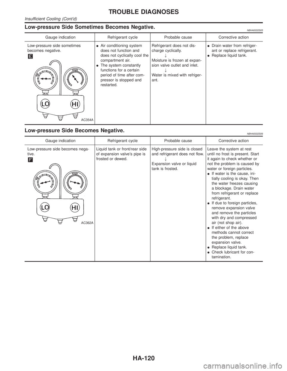
Low-pressure Side Sometimes Becomes Negative.NBHA0032S05
Gauge indication Refrigerant cycle Probable cause Corrective action
Low-pressure side sometimes
becomes negative.
AC354A
IAir conditioning system
does not function and
does not cyclically cool the
compartment air.
IThe system constantly
functions for a certain
period of time after com-
pressor is stopped and
restarted.Refrigerant does not dis-
charge cyclically.
"
Moisture is frozen at expan-
sion valve outlet and inlet.
"
Water is mixed with refriger-
ant.IDrain water from refriger-
ant or replace refrigerant.
IReplace liquid tank.
Low-pressure Side Becomes Negative.NBHA0032S06
Gauge indication Refrigerant cycle Probable cause Corrective action
Low-pressure side becomes nega-
tive.
AC362A
Liquid tank or front/rear side
of expansion valve's pipe is
frosted or dewed.High-pressure side is closed
and refrigerant does not flow.
"
Expansion valve or liquid
tank is frosted.Leave the system at rest
until no frost is present. Start
it again to check whether or
not the problem is caused by
water or foreign particles.
IIf water is the cause, ini-
tially cooling is okay. Then
the water freezes causing
a blockage. Drain water
from refrigerant or replace
refrigerant.
IIf due to foreign particles,
remove expansion valve
and remove the particles
with dry and compressed
air (not shop air).
IIf either of the above
methods cannot correct
the problem, replace
expansion valve.
IReplace liquid tank.
ICheck lubricant for con-
tamination.
TROUBLE DIAGNOSES
Insufficient Cooling (Cont'd)
HA-120
Page 1999 of 2395

NBMA0003
General maintenance includes those items which should be checked during the normal day-to-day operation
of the vehicle. They are essential if the vehicle is to continue operating properly. The owners can perform
checks and inspections themselves or they can have their INFINITI dealers do them.
OUTSIDE THE VEHICLE
The maintenance items listed here should be performed from time to time, unless otherwise specified.
ItemReference page
TiresCheck the pressure with a gauge periodically when at a service station,
including the spare, and adjust to the specified pressure if necessary. Check
carefully for damage, cuts or excessive wear.Ð
Wheel nutsWhen checking the tires, make sure no nuts are missing, and check for any
loose nuts. Tighten if necessary.Ð
Tire rotationTires should be rotated every 12,000 km (7,500 miles). MA-24
Wheel alignment and
balanceIf the vehicle pulls to either side while driving on a straight and level road, or
if you detect uneven or abnormal tire wear, there may be a need for wheel
alignment. If the steering wheel or seat vibrates at normal highway speeds,
wheel balancing may be needed.MA-24, SU-6, ªFront
Wheel Alignmentº
Windshield wiper
bladesCheck for cracks or wear if they do not wipe properly. Ð
Doors and engine
hoodCheck that all doors and the engine hood operate smoothly as well as the
trunk lid and back hatch. Also make sure that all latches lock securely. Lubri-
cate if necessary. Make sure that the secondary latch keeps the hood from
opening when the primary latch is released.
When driving in areas using road salt or other corrosive materials, check
lubrication frequently.MA-27
INSIDE THE VEHICLE
The maintenance items listed here should be checked on a regular basis, such as when performing periodic maintenance, cleaning the
vehicle, etc.
ItemReference page
LampsMake sure that the headlamps, stop lamps, tail lamps, turn signal lamps, and
other lamps are all operating properly and installed securely. Also check
headlamp aim.Ð
Warning lamps and
buzzers/chimesMake sure that all warning lamps and buzzers/chimes are operating properly. Ð
Windshield wiper
and washerCheck that the wipers and washer operate properly and that the wipers do
not streak.Ð
Windshield defrosterCheck that the air comes out of the defroster outlets properly and in sufficient
quantity when operating the heater or air conditioning.Ð
Steering wheelCheck that it has the specified play. Be sure to check for changes in the
steering condition, such as excessive play, hard steering or strange noises.
Free play: Less than 35 mm (1.38 in)Ð
SeatsCheck seat position controls such as seat adjusters, seatback recliner, etc. to
make sure they operate smoothly and that all latches lock securely in every
position. Check that the head restrains move up and down smoothly and that
the locks (if equipped) hold securely in all latched positions. Check that the
latches lock securely for folding-down rear seatbacks.Ð
Seat beltsCheck that all parts of the seat belt system (e.g. buckles, anchors, adjusters
and retractors) operate properly and smoothly and are installed securely.
Check the belt webbing for cuts, fraying, wear or damage.MA-28, RS-7, ªSeat Belt
Inspectionº
BrakesCheck that the brake does not pull the vehicle to one side when applied. Ð
GENERAL MAINTENANCE
MA-4
Page 2009 of 2395
SMA857C
SMA858C
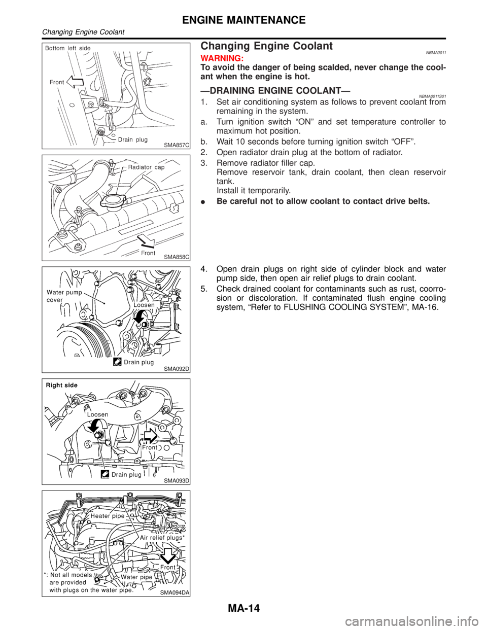
Changing Engine CoolantNBMA0011WARNING:
To avoid the danger of being scalded, never change the cool-
ant when the engine is hot.
ÐDRAINING ENGINE COOLANTÐNBMA0011S011. Set air conditioning system as follows to prevent coolant from
remaining in the system.
a. Turn ignition switch ªONº and set temperature controller to
maximum hot position.
b. Wait 10 seconds before turning ignition switch ªOFFº.
2. Open radiator drain plug at the bottom of radiator.
3. Remove radiator filler cap.
Remove reservoir tank, drain coolant, then clean reservoir
tank.
Install it temporarily.
IBe careful not to allow coolant to contact drive belts.
SMA092D
SMA093D
SMA094DA
4. Open drain plugs on right side of cylinder block and water
pump side, then open air relief plugs to drain coolant.
5. Check drained coolant for contaminants such as rust, coorro-
sion or discoloration. If contaminated flush engine cooling
system, ªRefer to FLUSHING COOLING SYSTEMº, MA-16.
ENGINE MAINTENANCE
Changing Engine Coolant
MA-14