2001 INFINITI QX4 Bleed
[x] Cancel search: BleedPage 409 of 2395

SBR116BG
Installation=NBBR0027CAUTION:
IBe careful not to deform or bend brake pipes during instal-
lation of booster.
IReplace clevis pin if damaged.
IRefill with new brake fluid ªDOT 3º.
INever reuse drained brake fluid.
ITake care not to damage brake booster mounting bolt
thread when installing. Due to the narrow angle of
installation, the threads can be damaged by the dash
panel.
1. Before fitting booster, temporarily adjust clevis to dimension
shown.
2. Fit booster, then secure mounting nuts (brake pedal bracket to
brake booster) lightly.
3. Connect brake pedal and booster input rod with clevis pin.
4. Secure mounting nuts.
Specification: 13 - 16 N´m (1.3 - 1.6 kg-m,9-12ft-lb)
5. Install master cylinder. Refer to ªInstallationº in ªMASTER
CYLINDERº, BR-18.
6. Adjust brake pedal height and free play. Refer to ªAdjustmentº
in ªBRAKE PEDAL AND BRACKETº, BR-14.
7. Secure lock nut for clevis.
: 16 - 22 N´m (1.6 - 2.2 kg-m, 12 - 16 ft-lb)
8. Bleed air. Refer to ªBleeding Brake Systemº, BR-8.
BRAKE BOOSTER
Installation
BR-20
Page 411 of 2395

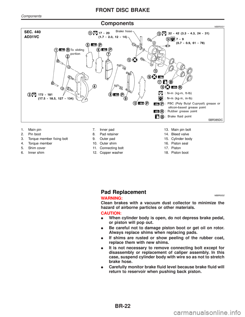
ComponentsNBBR0031
SBR385DC
1. Main pin
2. Pin boot
3. Torque member fixing bolt
4. Torque member
5. Shim cover
6. Inner shim7. Inner pad
8. Pad retainer
9. Outer pad
10. Outer shim
11. Connecting bolt
12. Copper washer13. Main pin bolt
14. Bleed valve
15. Cylinder body
16. Piston seal
17. Piston
18. Piston boot
Pad ReplacementNBBR0032WARNING:
Clean brakes with a vacuum dust collector to minimize the
hazard of airborne particles or other materials.
CAUTION:
IWhen cylinder body is open, do not depress brake pedal,
or piston will pop out.
IBe careful not to damage piston boot or get oil on rotor.
Always replace shims when replacing pads.
IIf shims are rusted or show peeling of the rubber coat,
replace them with new shims.
IIt is not necessary to remove connecting bolt except for
disassembly or replacement of caliper assembly. In this
case, suspend cylinder body with wire so as not to stretch
brake hose.
ICarefully monitor brake fluid level because brake fluid will
return to reservoir when pushing back piston.
FRONT DISC BRAKE
Components
BR-22
Page 414 of 2395

SBR020B
ThicknessNBBR0035S0202Thickness variation (At least 8 positions):
Maximum 0.015 mm (0.0006 in)
If thickness variation exceeds the specification, turn rotor with on-
car brake lathe.
Rotor repair limit:
26.0 mm (1.024 in)
SBR574
AssemblyNBBR00361. Insert piston seal into groove on cylinder body.
2. With piston boot fitted to piston, insert piston boot into groove
on cylinder body and install piston.
3. Properly secure piston boot
SBR387D
InstallationNBBR0037CAUTION:
IRefill with new brake fluid ªDOT 3º.
INever reuse drained brake fluid.
1. Install caliper assembly.
2. Install brake hose to caliper securely.
3. Install all parts and secure all bolts.
4. Bleed air. Refer to ªBleeding Brake Systemº, BR-8.
Brake Burnishing ProcedureNBBR0086When experiencing soft brake pedal feel at very low mileage, or
after replacing the rotor, burnish the brake pad contact surfaces
according to the following procedures.
CAUTION:
Only perform this procedure under safe road and traffic con-
ditions. Use extreme caution.
1. Drive the vehicle on a straight smooth road at 50 km/h (31
MPH).
2. Use medium brake pedal/foot effort to bring the vehicle to a
complete stop from 50 km/h (31 MPH). Adjust brake pedal/foot
pressure such that vehicle stopping time equals 3 to 5 sec-
onds.
3. To cool the brake system, drive the vehicle at 50 km/h (31
MPH) for 1 minute without stopping.
4. Repeat steps 1 to 3 10 times or more to complete the burnish-
ing procedure.
GI
MA
EM
LC
EC
FE
AT
TF
PD
AX
SU
ST
RS
BT
HA
SC
EL
IDX
FRONT DISC BRAKE
Inspection (Cont'd)
BR-25
Page 415 of 2395

ComponentsNBBR0038
SBR757DA
1. Shoe hold pin
2. Plug
3. Back plate
4. Check plug
5. Spring
6. Shoe (leading side)
7. Air bleeder
8. Spring
9. Piston cup10. Piston
11. Boot
12. Retainer ring
13. Toggle lever
14. Wave washer
15. Shoe (trailing side)
16. Adjuster
17. Boot
18. Piston19. Piston cup
20. Wheel cylinder
21. Adjuster lever
22. Spring seat
23. Shoe hold spring
24. Retainer
25. Adjuster spring
26. Return spring (upper)
27. Return spring (lower)
RemovalNBBR0039WARNING:
Clean brake lining with a vacuum dust collector to minimize
the hazard of airborne asbestos or other materials.
CAUTION:
Make sure parking brake lever is released completely.
SBR264CA
1. Release parking brake lever fully, then remove drum.
If drum is hard to remove, the following procedures
should be carried out.
a. Remove plug. Then shorten adjuster to make clearance
between brake shoe and drum as shown.
REAR DRUM BRAKE
Components
BR-26
Page 418 of 2395

SBR217B
3. Shorten adjuster by rotating it.
IPay attention to direction of adjuster.
Wheel Screw Depression
Left Left-hand thread Yes
Right Right-hand thread No
SBR279B
4. Connect parking brake cable to toggle lever.
5. Install all parts.
Be careful not to damage wheel cylinder piston boots.
6. Check all parts are installed properly.
Pay attention to direction of adjuster assembly.
7. Install brake drum.
8. When installing new wheel cylinder or overhauling wheel
cylinder, bleed air. Refer to ªBleeding Brake Systemº, BR-8.
9. Adjust parking brake. Refer to ªAdjustmentº, ªPARKING
BRAKE CONTROLº, BR-31.
GI
MA
EM
LC
EC
FE
AT
TF
PD
AX
SU
ST
RS
BT
HA
SC
EL
IDX
REAR DRUM BRAKE
Installation (Cont'd)
BR-29
Page 459 of 2395

2 CHECK MECHANICAL BRAKE SYSTEM PERFORMANCE
Disconnect ABS actuator and electric unit connector and check whether brake is effective.
Does brake system function properly when brake pedal is depressed?
Ye s©GO TO 3.
No©Perform Preliminary Check. Refer to BR-50.
3 CHECK WARNING LAMP INDICATION
Ensure warning lamp remains off while driving.
SBR672E
Is warning lamp turned off?
Ye s©GO TO 4.
No©Carry out self-diagnosis. Refer to BR-41, BR-44.
4 CHECK WHEEL SENSOR
1. Check wheel sensor connector for terminal damage or loose connection.
2. Perform wheel sensor mechanical check. Refer to ª7. CHECK SENSOR ROTORº in ªDIAGNOSTIC PROCEDUREº,
ªWheel Sensor or Rotorº, BR-56.
Is wheel sensor mechanism OK?
Ye s©Check ABS actuator and electric unit pin terminals for damage or the connection of ABS
actuator and electric unit harness connector.
Reconnect ABS actuator and electric unit harness connector.
Then retest.
No©Repair.
3. Long Stopping DistanceNBBR0109
1 CHECK MECHANICAL BRAKE SYSTEM PERFORMANCE
Disconnect ABS actuator and electric unit connector and check whether stopping distance is still long.
Does brake system function properly when brake pedal is depressed?
Ye s©Perform Preliminary Check and air bleeding (if necessary).
No©Go to ª3. CHECK WARNING LAMP INDICATIONº in ª2. Unexpected Pedal Actionº,
BR-70.
TROUBLE DIAGNOSES FOR SYMPTOMSABS
2. Unexpected Pedal Action (Cont'd)
BR-70
Page 471 of 2395

ABS Actuator and Electric UnitNBBR0079S07
SBR468E
REMOVALNBBR0079S07011. Disconnect battery cable.
2. Drain brake fluid. Refer to ªChanging Brake Fluidº, BR-7.
3. Remove mounting bracket fixing bolts and nuts.
4. Disconnect connector, brake pipes and remove fixing nuts and
actuator ground cable.
INSTALLATIONNBBR0079S0702CAUTION:
After installation, refill brake fluid. Then bleed air. Refer to
ªBleeding Brake Systemº, BR-8.
1. Tighten actuator ground cable.
Place ground cable at a notch of mounting bracket.
2. Connect brake pipes temporarily.
3. Tighten fixing bolts and nuts.
4. Tighten brake pipes.
5. Connect connector and battery cable.
REMOVAL AND INSTALLATIONABS
ABS Actuator and Electric Unit
BR-82
Page 1961 of 2395

A
AAC/V - Wiring diagram ...............................EC-425
ABS - Wiring diagram ....................................BR-37
ABS sensor rotor ........................................AX-6, 19
Absolute pressure sensor ............................EC-158
A/C air flow .....................................................HA-25
A/C component layout ....................................HA-19
A/C compressor clutch removal and
installation .................................................HA-150
A/C compressor precaution..............................HA-6
A/C compressor special service tool..............HA-10
A/C control operation (auto A/C) ....................HA-23
A/C diagnostic work flow (auto A/C) ..............HA-65
A/C HFC134a (R134a) system
precaution .....................................................HA-2
A/C HFC134a (R134a) system service
procedure ..................................................HA-144
A/C HFC134a (R134a) system service
tools.............................................................HA-11
A/C HFC134a system service equip-
ment precaution ............................................HA-7
A/C lubricant (R134a)...................................HA-146
A/C operational check ....................................HA-66
A/C performance chart .................................HA-116
A/C performance test diagnoses ..................HA-114
A/C relay .......................................................HA-110
A/C self-diagnoses (auto A/C)........................HA-44
A/C service data specification ......................HA-160
A/C system description (auto A/C) .................HA-23
A/C trouble diagnoses (auto A/C) ..................HA-27
A/C, A - Wiring diagram ...........................HA-31, 36
Accelerator control system ...............................FE-3
Accelerator wire adjustment .............................FE-3
Actuator lever (Transfer) ...............................TF-120
Air bag ............................................................RS-10
Air bag disposal..............................................RS-22
Air bag precautions ...........................................GI-3
Air bleeding for brake system ..........................BR-8
Air cleaner filter replacement .........................MA-17
Air conditioner cut control ..............................EC-31
Air flow meter - See Mass air flow
sensor .......................................................EC-150
Air mix door control linkage adjustment.........HA-85
Air mix. door motor ................................HA-82, 141
Air spoiler, rear................................................BT-35
All - mode 4WD system ..................................TF-10
Alternator ........................................................SC-28
Ambient sensor ............................................HA-129
Angular tightening application..........................EM-3
Antenna - See Power antenna .....................EL-169
Anti-lock brake system - Wiring
diagram .......................................................BR-37
AP/SEN - Wiring diagram ............................EC-160
ASCD (automatic speed control device) ......EL-221
ASCD - Wiring diagram ................................EL-225
A/T - Wiring diagram - AT - FTS ...................AT-107
A/T - Wiring diagram - AT - MAIN ...................AT-96
A/T - Wiring diagram - AT - PNP/SW............AT-101A/T - Wiring diagram - AT - VSS A/T ............AT-113
A/T control ....................................................EC-440
A/T diagnosis communication line................EC-603
A/T fluid temperature sensor .........................AT-110
A/T self-diagnoses...........................................AT-46
A/T shift lock system .....................................AT-265
A/T shift lock system - Wiring diagram .........AT-266
A/T trouble diagnoses .....................................AT-53
A/T Wiring diagram - AT - ENG SS...............AT-117
A/T Wiring diagram AT - 1ST ........................AT-123
A/T Wiring diagram AT - 2ND .......................AT-129
A/T Wiring diagram AT - 3RD .......................AT-135
A/T Wiring diagram AT - 4TH ........................AT-142
A/T Wiring diagram AT - BA/FTS ..................AT-192
A/T Wiring diagram AT - LPSV .....................AT-164
A/T Wiring diagram AT - NONDTC ...............AT-215
A/T Wiring diagram AT - OVRCSV ...............AT-187
A/T Wiring diagram AT - SSV/A ....................AT-169
A/T Wiring diagram AT - SSV/B ....................AT-173
A/T Wiring diagram AT - TCCSIG .................AT-156
A/T Wiring diagram AT - TCV .......................AT-150
A/T Wiring diagram AT - TPS........................AT-179
A/T Wiring diagram AT - VSSMTR................AT-199
AT/C - Wiring diagram ..................................EC-442
ATP switch.....................................................TF-112
ATP warning lamp .........................................TF-102
Audio .............................................................EL-160
AUDIO - Wiring diagram ...............................EL-162
Audio and A/C control removal and
installation - See Instrument panel .............BT-21
AUT/DP - Wiring diagram .............................EL-191
Auto air conditioner - Wiring diagram ......HA-31, 36
Automatic amplifier...................................HA-40, 72
Automatic drive positioner ............................EL-186
Automatic speed control system - See
ASCD ........................................................EL-221
Automatic transmission fluid
replacement ................................................MA-21
Automatic transmission number ......................GI-43
Auxiliary air control (AAC) valve ..................EC-422
Axle housing (rear) .........................................AX-19
B
Back door ........................................................BT-15
Back door opener - See Back door ................BT-15
Back door trim.................................................BT-34
Back-up lamp ..................................................EL-69
BACK/L - Wiring diagram................................EL-69
Ball joint (front) ...............................................SU-12
Base idle air volume initialiging......................EC-57
Basic inspection ...........................................EC-101
Battery ..............................................................SC-4
Battery/Starting/Charging System
Tester ................................................SC-7, 12, 21
Blower motor ..................................................HA-95
Body alignment ...............................................BT-57
Brake booster .................................................BR-19
Brake control valve (Proportioning
valve)...........................................................BR-11
ALPHABETICAL INDEX
IDX-2