2001 INFINITI QX4 service
[x] Cancel search: servicePage 1070 of 2395
11 CHECK EVAP CANISTER
Weigh the EVAP canister with the EVAP canister vent control valve attached.
The weight should be less than 1.8 kg (4.0 lb).
OK or NG
OK (With CONSULT-II)©GO TO 13.
OK (Without CONSULT-
II)©GO TO 14.
NG©GO TO 12.
12 DETECT MALFUNCTIONING PART
Check the following.
IEVAP canister for damage
IEVAP hose between EVAP canister and water separator for clogging or poor connection
©Repair hose or replace EVAP canister.
13 CHECK EVAP CANISTER PURGE VOLUME CONTROL SOLENOID VALVE OPERATION
With CONSULT-II
1. Disconnect vacuum hose to EVAP canister purge volume control solenoid valve at EVAP service port.
2. Start engine.
3. Perform ªPURG VOL CONT/Vº in ªACTIVE TESTº mode.
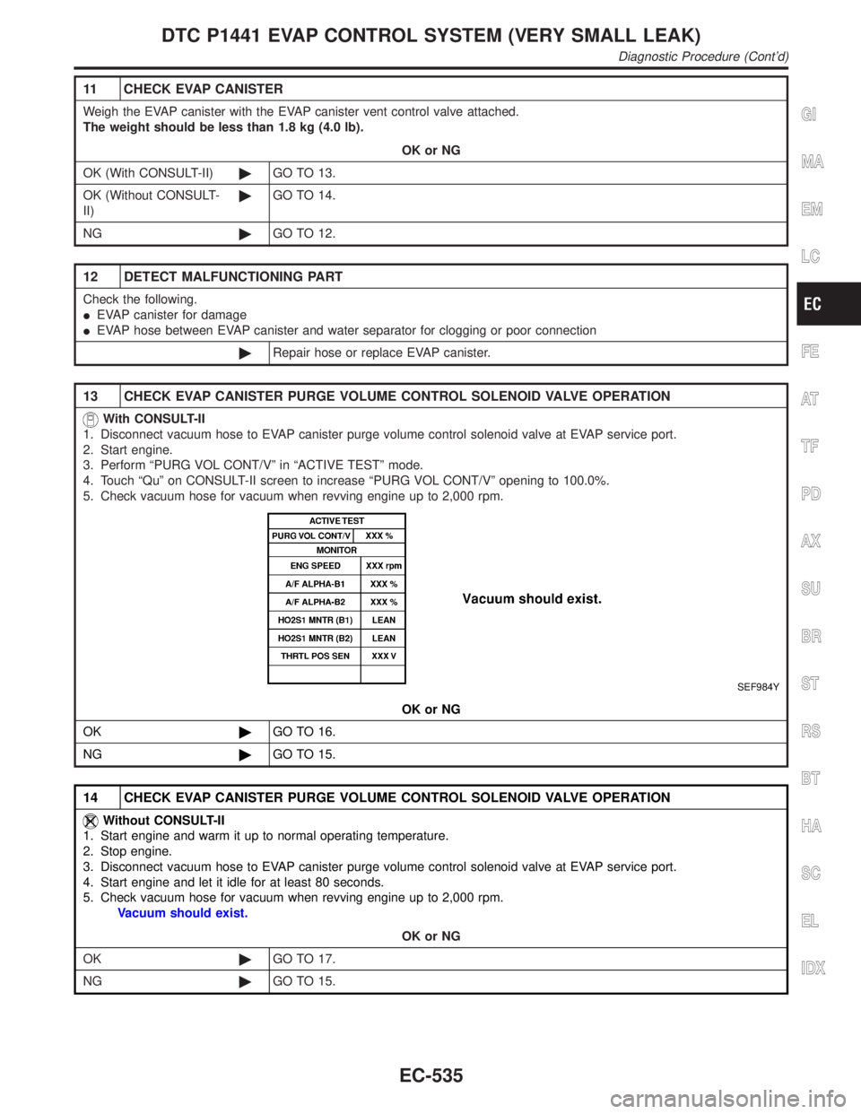
4. Touch ªQuº on CONSULT-II screen to increase ªPURG VOL CONT/Vº opening to 100.0%.
5. Check vacuum hose for vacuum when revving engine up to 2,000 rpm.
SEF984Y
OK or NG
OK©GO TO 16.
NG©GO TO 15.
14 CHECK EVAP CANISTER PURGE VOLUME CONTROL SOLENOID VALVE OPERATION
Without CONSULT-II
1. Start engine and warm it up to normal operating temperature.
2. Stop engine.
3. Disconnect vacuum hose to EVAP canister purge volume control solenoid valve at EVAP service port.
4. Start engine and let it idle for at least 80 seconds.
5. Check vacuum hose for vacuum when revving engine up to 2,000 rpm.
Vacuum should exist.
OK or NG
OK©GO TO 17.
NG©GO TO 15.
GI
MA
EM
LC
FE
AT
TF
PD
AX
SU
BR
ST
RS
BT
HA
SC
EL
IDX
DTC P1441 EVAP CONTROL SYSTEM (VERY SMALL LEAK)
Diagnostic Procedure (Cont'd)
EC-535
Page 1099 of 2395
Diagnostic Procedure=NBEC0337
1 CHECK EVAP CANISTER
1. Turn ignition switch ªOFFº.
2. Check EVAP canister for cracks.
OK or NG
OK (With CONSULT-II)©GO TO 2.
OK (Without CONSULT-
II)©GO TO 3.
NG©Replace EVAP canister.
2 CHECK PURGE FLOW
With CONSULT-II
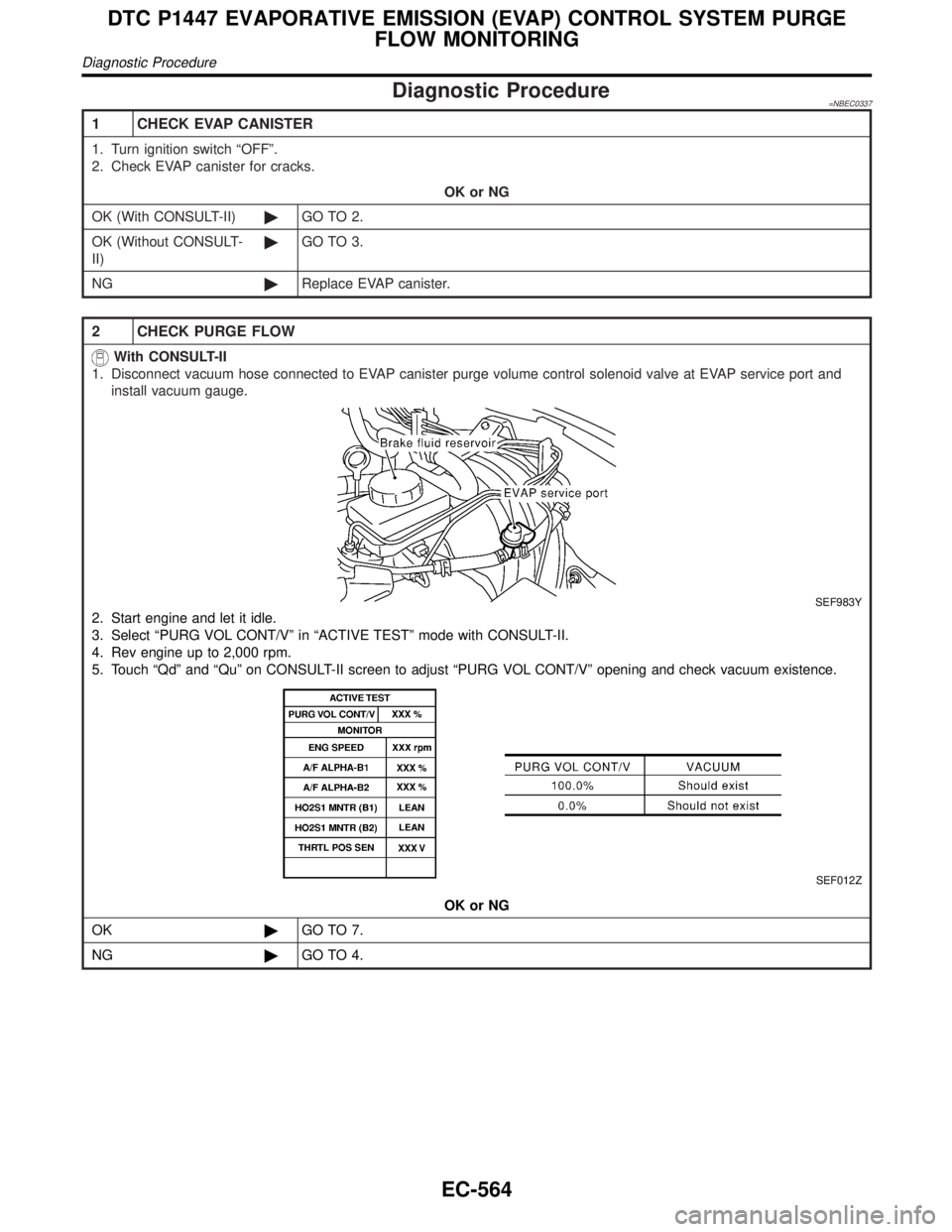
1. Disconnect vacuum hose connected to EVAP canister purge volume control solenoid valve at EVAP service port and
install vacuum gauge.
SEF983Y
2. Start engine and let it idle.
3. Select ªPURG VOL CONT/Vº in ªACTIVE TESTº mode with CONSULT-II.
4. Rev engine up to 2,000 rpm.
5. Touch ªQdº and ªQuº on CONSULT-II screen to adjust ªPURG VOL CONT/Vº opening and check vacuum existence.
SEF012Z
OK or NG
OK©GO TO 7.
NG©GO TO 4.
DTC P1447 EVAPORATIVE EMISSION (EVAP) CONTROL SYSTEM PURGE
FLOW MONITORING
Diagnostic Procedure
EC-564
Page 1100 of 2395
3 CHECK PURGE FLOW
Without CONSULT-II
1. Start engine and warm it up to normal operating temperature.
2. Stop engine.
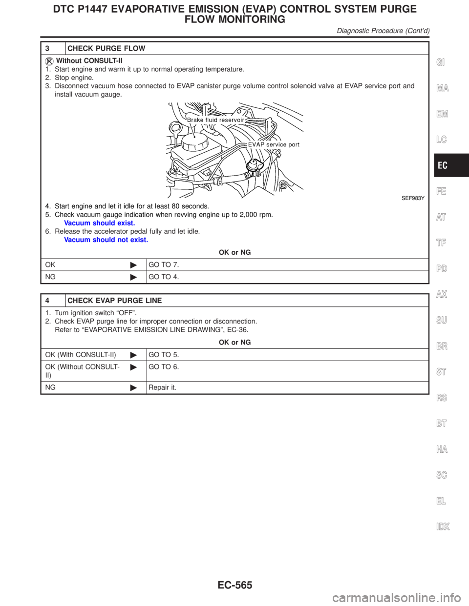
3. Disconnect vacuum hose connected to EVAP canister purge volume control solenoid valve at EVAP service port and
install vacuum gauge.
SEF983Y
4. Start engine and let it idle for at least 80 seconds.
5. Check vacuum gauge indication when revving engine up to 2,000 rpm.
Vacuum should exist.
6. Release the accelerator pedal fully and let idle.
Vacuum should not exist.
OK or NG
OK©GO TO 7.
NG©GO TO 4.
4 CHECK EVAP PURGE LINE
1. Turn ignition switch ªOFFº.
2. Check EVAP purge line for improper connection or disconnection.
Refer to ªEVAPORATIVE EMISSION LINE DRAWINGº, EC-36.
OK or NG
OK (With CONSULT-II)©GO TO 5.
OK (Without CONSULT-
II)©GO TO 6.
NG©Repair it.
GI
MA
EM
LC
FE
AT
TF
PD
AX
SU
BR
ST
RS
BT
HA
SC
EL
IDX
DTC P1447 EVAPORATIVE EMISSION (EVAP) CONTROL SYSTEM PURGE
FLOW MONITORING
Diagnostic Procedure (Cont'd)
EC-565
Page 1101 of 2395
5 CHECK EVAP PURGE HOSE AND PURGE PORT
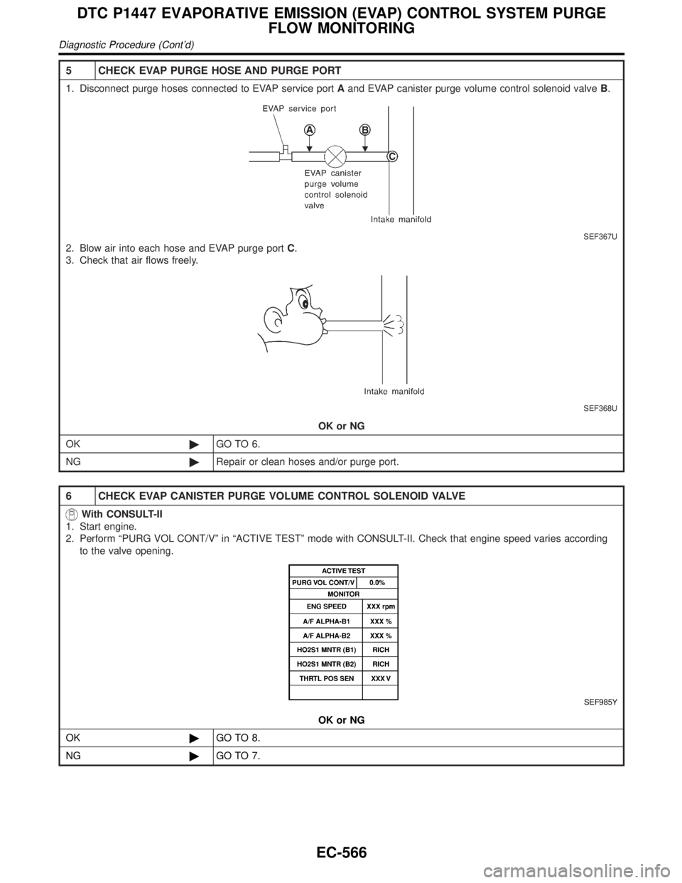
1. Disconnect purge hoses connected to EVAP service portAand EVAP canister purge volume control solenoid valveB.
SEF367U
2. Blow air into each hose and EVAP purge portC.
3. Check that air flows freely.
SEF368U
OK or NG
OK©GO TO 6.
NG©Repair or clean hoses and/or purge port.
6 CHECK EVAP CANISTER PURGE VOLUME CONTROL SOLENOID VALVE
With CONSULT-II
1. Start engine.
2. Perform ªPURG VOL CONT/Vº in ªACTIVE TESTº mode with CONSULT-II. Check that engine speed varies according
to the valve opening.
SEF985Y
OK or NG
OK©GO TO 8.
NG©GO TO 7.
DTC P1447 EVAPORATIVE EMISSION (EVAP) CONTROL SYSTEM PURGE
FLOW MONITORING
Diagnostic Procedure (Cont'd)
EC-566
Page 1184 of 2395
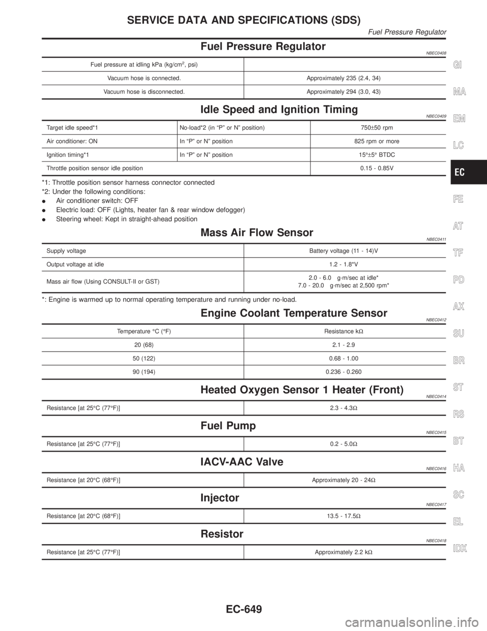
Fuel Pressure RegulatorNBEC0408
Fuel pressure at idling kPa (kg/cm2, psi)
Vacuum hose is connected. Approximately 235 (2.4, 34)
Vacuum hose is disconnected. Approximately 294 (3.0, 43)
Idle Speed and Ignition TimingNBEC0409
Target idle speed*1 No-load*2 (in ªPº or Nº position) 750±50 rpm
Air conditioner: ON In ªPº or Nº position 825 rpm or more
Ignition timing*1 In ªPº or Nº position 15ɱ5É BTDC
Throttle position sensor idle position0.15 - 0.85V
*1: Throttle position sensor harness connector connected
*2: Under the following conditions:
IAir conditioner switch: OFF
IElectric load: OFF (Lights, heater fan & rear window defogger)
ISteering wheel: Kept in straight-ahead position
Mass Air Flow SensorNBEC0411
Supply voltageBattery voltage (11 - 14)V
Output voltage at idle1.2 - 1.8*V
Mass air flow (Using CONSULT-II or GST)2.0 - 6.0 g´m/sec at idle*
7.0 - 20.0 g´m/sec at 2,500 rpm*
*: Engine is warmed up to normal operating temperature and running under no-load.
Engine Coolant Temperature SensorNBEC0412
Temperature ÉC (ÉF) Resistance kW
20 (68) 2.1 - 2.9
50 (122) 0.68 - 1.00
90 (194) 0.236 - 0.260
Heated Oxygen Sensor 1 Heater (Front)NBEC0414
Resistance [at 25ÉC (77ÉF)]2.3 - 4.3W
Fuel PumpNBEC0415
Resistance [at 25ÉC (77ÉF)]0.2 - 5.0W
IACV-AAC ValveNBEC0416
Resistance [at 20ÉC (68ÉF)]Approximately 20 - 24W
InjectorNBEC0417
Resistance [at 20ÉC (68ÉF)]13.5 - 17.5W
ResistorNBEC0418
Resistance [at 25ÉC (77ÉF)]Approximately 2.2 kW
GI
MA
EM
LC
FE
AT
TF
PD
AX
SU
BR
ST
RS
BT
HA
SC
EL
IDX
SERVICE DATA AND SPECIFICATIONS (SDS)
Fuel Pressure Regulator
EC-649
Page 1185 of 2395
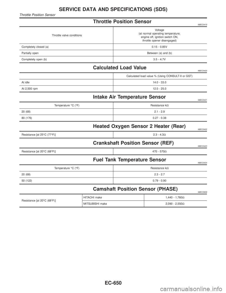
Throttle Position SensorNBEC0419
Throttle valve conditionsVoltage
(at normal operating temperature,
engine off, ignition switch ON,
throttle opener disengaged)
Completely closed (a)0.15 - 0.85V
Partially openBetween (a) and (b)
Completely open (b)3.5 - 4.7V
Calculated Load ValueNBEC0420
Calculated load value % (Using CONSULT-II or GST)
At idle14.0 - 33.0
At 2,500 rpm12.0 - 25.0
Intake Air Temperature SensorNBEC0421
Temperature ÉC (ÉF) Resistance kW
20 (68)2.1 - 2.9
80 (176)0.27 - 0.38
Heated Oxygen Sensor 2 Heater (Rear)NBEC0422
Resistance [at 25ÉC (77ÉF)]2.3 - 4.3W
Crankshaft Position Sensor (REF)NBEC0423
Resistance [at 20ÉC (68ÉF)]470 - 570W
Fuel Tank Temperature SensorNBEC0424
Temperature ÉC (ÉF) Resistance kW
20 (68)2.3 - 2.7
50 (122)0.79 - 0.90
Camshaft Position Sensor (PHASE)NBEC0639
Resistance [at 20ÉC (68ÉF)]HITACHI make 1,440 - 1,760W
MITSUBISHI make 2,090 - 2,550W
SERVICE DATA AND SPECIFICATIONS (SDS)
Throttle Position Sensor
EC-650
Page 1189 of 2395
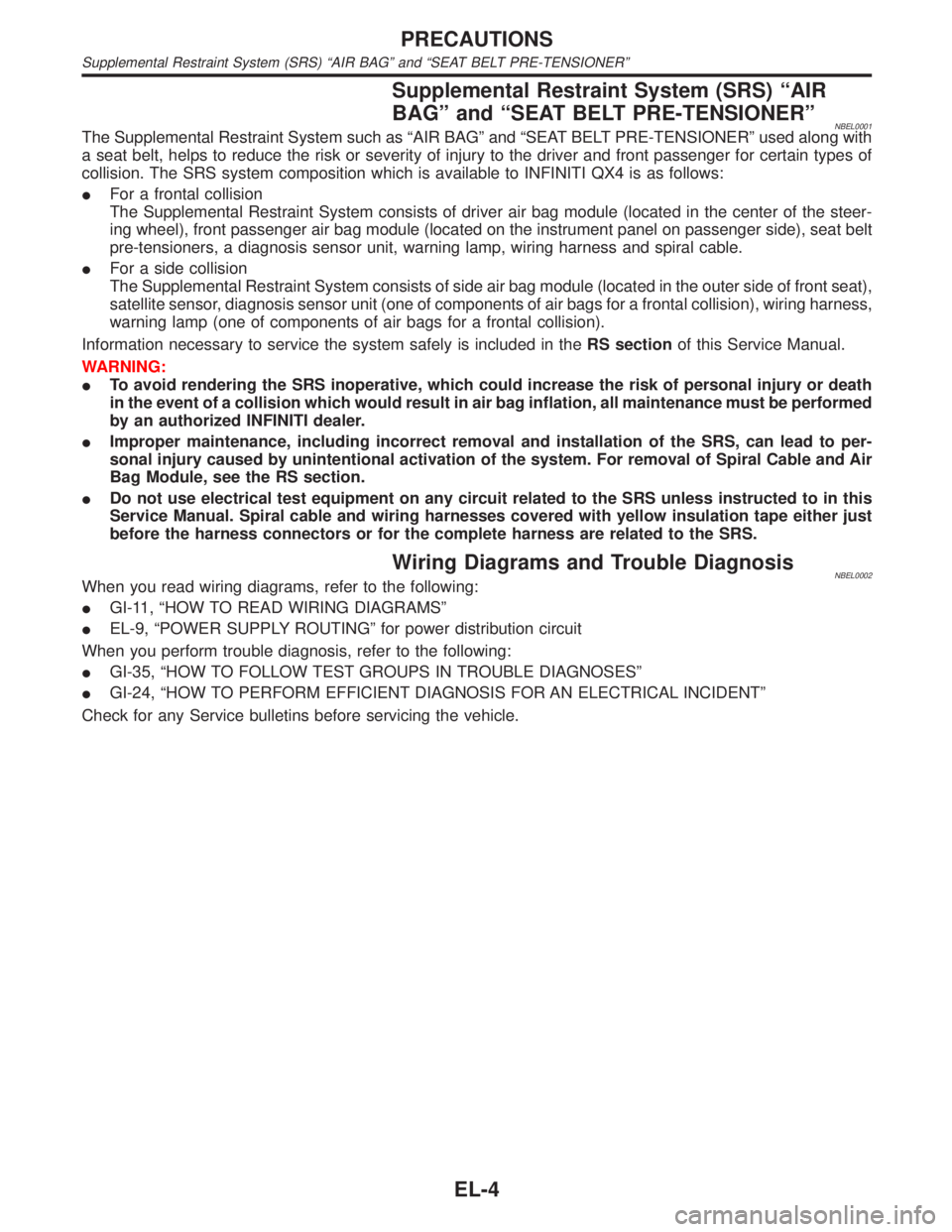
Supplemental Restraint System (SRS) ªAIR
BAGº and ªSEAT BELT PRE-TENSIONERº
NBEL0001The Supplemental Restraint System such as ªAIR BAGº and ªSEAT BELT PRE-TENSIONERº used along with
a seat belt, helps to reduce the risk or severity of injury to the driver and front passenger for certain types of
collision. The SRS system composition which is available to INFINITI QX4 is as follows:
IFor a frontal collision
The Supplemental Restraint System consists of driver air bag module (located in the center of the steer-
ing wheel), front passenger air bag module (located on the instrument panel on passenger side), seat belt
pre-tensioners, a diagnosis sensor unit, warning lamp, wiring harness and spiral cable.
IFor a side collision
The Supplemental Restraint System consists of side air bag module (located in the outer side of front seat),
satellite sensor, diagnosis sensor unit (one of components of air bags for a frontal collision), wiring harness,
warning lamp (one of components of air bags for a frontal collision).
Information necessary to service the system safely is included in theRS sectionof this Service Manual.
WARNING:
ITo avoid rendering the SRS inoperative, which could increase the risk of personal injury or death
in the event of a collision which would result in air bag inflation, all maintenance must be performed
by an authorized INFINITI dealer.
IImproper maintenance, including incorrect removal and installation of the SRS, can lead to per-
sonal injury caused by unintentional activation of the system. For removal of Spiral Cable and Air
Bag Module, see the RS section.
IDo not use electrical test equipment on any circuit related to the SRS unless instructed to in this
Service Manual. Spiral cable and wiring harnesses covered with yellow insulation tape either just
before the harness connectors or for the complete harness are related to the SRS.
Wiring Diagrams and Trouble DiagnosisNBEL0002When you read wiring diagrams, refer to the following:
IGI-11, ªHOW TO READ WIRING DIAGRAMSº
IEL-9, ªPOWER SUPPLY ROUTINGº for power distribution circuit
When you perform trouble diagnosis, refer to the following:
IGI-35, ªHOW TO FOLLOW TEST GROUPS IN TROUBLE DIAGNOSESº
IGI-24, ªHOW TO PERFORM EFFICIENT DIAGNOSIS FOR AN ELECTRICAL INCIDENTº
Check for any Service bulletins before servicing the vehicle.
PRECAUTIONS
Supplemental Restraint System (SRS) ªAIR BAGº and ªSEAT BELT PRE-TENSIONERº
EL-4
Page 1225 of 2395
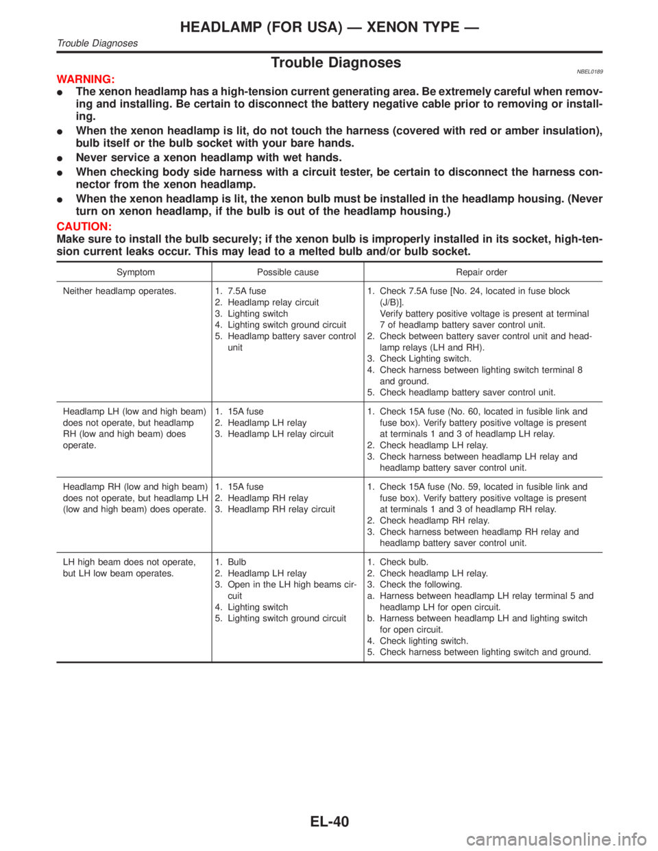
Trouble DiagnosesNBEL0189WARNING:
IThe xenon headlamp has a high-tension current generating area. Be extremely careful when remov-
ing and installing. Be certain to disconnect the battery negative cable prior to removing or install-
ing.
IWhen the xenon headlamp is lit, do not touch the harness (covered with red or amber insulation),
bulb itself or the bulb socket with your bare hands.
INever service a xenon headlamp with wet hands.
IWhen checking body side harness with a circuit tester, be certain to disconnect the harness con-
nector from the xenon headlamp.
IWhen the xenon headlamp is lit, the xenon bulb must be installed in the headlamp housing. (Never
turn on xenon headlamp, if the bulb is out of the headlamp housing.)
CAUTION:
Make sure to install the bulb securely; if the xenon bulb is improperly installed in its socket, high-ten-
sion current leaks occur. This may lead to a melted bulb and/or bulb socket.
Symptom Possible cause Repair order
Neither headlamp operates. 1. 7.5A fuse
2. Headlamp relay circuit
3. Lighting switch
4. Lighting switch ground circuit
5. Headlamp battery saver control
unit1. Check 7.5A fuse [No. 24, located in fuse block
(J/B)].
Verify battery positive voltage is present at terminal
7 of headlamp battery saver control unit.
2. Check between battery saver control unit and head-
lamp relays (LH and RH).
3. Check Lighting switch.
4. Check harness between lighting switch terminal 8
and ground.
5. Check headlamp battery saver control unit.
Headlamp LH (low and high beam)
does not operate, but headlamp
RH (low and high beam) does
operate.1. 15A fuse
2. Headlamp LH relay
3. Headlamp LH relay circuit1. Check 15A fuse (No. 60, located in fusible link and
fuse box). Verify battery positive voltage is present
at terminals 1 and 3 of headlamp LH relay.
2. Check headlamp LH relay.
3. Check harness between headlamp LH relay and
headlamp battery saver control unit.
Headlamp RH (low and high beam)
does not operate, but headlamp LH
(low and high beam) does operate.1. 15A fuse
2. Headlamp RH relay
3. Headlamp RH relay circuit1. Check 15A fuse (No. 59, located in fusible link and
fuse box). Verify battery positive voltage is present
at terminals 1 and 3 of headlamp RH relay.
2. Check headlamp RH relay.
3. Check harness between headlamp RH relay and
headlamp battery saver control unit.
LH high beam does not operate,
but LH low beam operates.1. Bulb
2. Headlamp LH relay
3. Open in the LH high beams cir-
cuit
4. Lighting switch
5. Lighting switch ground circuit1. Check bulb.
2. Check headlamp LH relay.
3. Check the following.
a. Harness between headlamp LH relay terminal 5 and
headlamp LH for open circuit.
b. Harness between headlamp LH and lighting switch
for open circuit.
4. Check lighting switch.
5. Check harness between lighting switch and ground.
HEADLAMP (FOR USA) Ð XENON TYPE Ð
Trouble Diagnoses
EL-40