2001 INFINITI QX4 fog light
[x] Cancel search: fog lightPage 592 of 2395

SEF452Y
Idle Air Volume LearningNBEC0642
SEF454Y
SEF455Y
DESCRIPTIONNBEC0642S01ªIdle Air Volume Learningº is an operation to learn the idle air vol-
ume that keeps each engine within the specific range. It must be
performed under any of the following conditions:
IEach time IACV-AAC valve, throttle body or ECM is replaced.
IIdle speed or ignition timing is out of specification.
PRE-CONDITIONINGNBEC0642S02Before performing ªIdle Air Volume Learningº, make sure that all of
the following conditions are satisfied.
Learning will be cancelled if any of the following conditions are
missed for even a moment.
IBattery voltage: More than 12.9V (At idle)
IEngine coolant temperature: 70 - 99ÉC (158 - 210ÉF)
IPNP switch: ON
IElectric load switch: OFF
(Air conditioner, headlamp, rear window defogger)
On vehicles equipped with daytime running light systems, if
the parking brake is applied before the engine is started the
headlamp will not illuminate.
ICooling fan motor: Not operating
ISteering wheel: Neutral (Straight-ahead position)
IVehicle speed: Stopped
ITransmission: Warmed-up
For A/T models with CONSULT-II, drive vehicle until ªFLUID
TEMP SEº in ªDATA MONITORº mode of ªA/Tº system indi-
cates less than 0.9V.
For A/T models without CONSULT-II, drive vehicle for 10 min-
utes.
OPERATION PROCEDURENBEC0642S03With CONSULT-IINBEC0642S03011. Turn ignition switch ªONº and wait at least 1 second.
2. Turn ignition switch ªOFFº and wait at least 10 seconds.
3. Start engine and warm it up to normal operating temperature.
4. Check that all items listed under the topic ªPRE-CONDITION-
INGº (previously mentioned) are in good order.
5. Turn ignition switch ªOFFº and wait at least 10 seconds.
6. Start the engine and let it idle for at least 30 seconds.
7. Select ªIDLE AIR VOL LEARNº in ªWORK SUPPORTº mode.
8. Touch ªSTARTº and wait 20 seconds.
9. Make sure that ªCMPLTº is displayed on CONSULT-II screen.
If ªINCMPº is displayed, ªIdle Air Volume Learningº will not be
carried out successfully. In this case, find the cause of the
problem by referring to the NOTE below.
10. Rev up the engine two or three times. Make sure that idle
speed and ignition timing are within specifications.
ITEM SPECIFICATION
Idle speed 750±50 rpm (in ªPº or ªNº position)
Ignition timing 15ɱ5É BTDC (in ªPº or ªNº position)
GI
MA
EM
LC
FE
AT
TF
PD
AX
SU
BR
ST
RS
BT
HA
SC
EL
IDX
BASIC SERVICE PROCEDURE
Idle Air Volume Learning
EC-57
Page 623 of 2395
![INFINITI QX4 2001 Factory Service Manual Monitored item [Unit]ECM
input
signalsMain
signalsDescription Remarks
INT/A TEMP SE
[ÉC] or [ÉF]qqIThe intake air temperature determined
by the signal voltage of the intake air
temperature sensor is INFINITI QX4 2001 Factory Service Manual Monitored item [Unit]ECM
input
signalsMain
signalsDescription Remarks
INT/A TEMP SE
[ÉC] or [ÉF]qqIThe intake air temperature determined
by the signal voltage of the intake air
temperature sensor is](/manual-img/42/57027/w960_57027-622.png)
Monitored item [Unit]ECM
input
signalsMain
signalsDescription Remarks
INT/A TEMP SE
[ÉC] or [ÉF]qqIThe intake air temperature determined
by the signal voltage of the intake air
temperature sensor is indicated.
EVAP SYS PRES [V]qIThe signal voltage of EVAP control sys-
tem pressure sensor is displayed.
ABSOL PRES/SE [V]qIThe signal voltage of the absolute pres-
sure sensor is displayed.
FUEL LEVEL SE [V]qIThe signal voltage of the fuel level sen-
sor is displayed.
START SIGNAL
[ON/OFF]qqIIndicates [ON/OFF] condition from the
starter signal.IAfter starting the engine, [OFF] is dis-
played regardless of the starter signal.
CLSD THL POS
[ON/OFF]qqIIndicates idle position [ON/OFF] com-
puted by ECM according to the throttle
position sensor signal.
CLSD THL/P SW
[ON/OFF]qIIndicates mechanical contact [ON/OFF]
condition of the closed throttle position
switch.
AIR COND SIG
[ON/OFF]qqIIndicates [ON/OFF] condition of the air
conditioner switch as determined by the
air conditioner signal.
P/N POSI SW
[ON/OFF]qqIIndicates [ON/OFF] condition from the
park/neutral position (PNP) switch sig-
nal.
PW/ST SIGNAL
[ON/OFF]qqI[ON/OFF] condition of the power steer-
ing oil pressure switch determined by
the power steering oil pressure signal is
indicated.
LOAD SIGNAL
[ON/OFF]qqIIndicates [ON/OFF] condition from the
electrical load signal and/or lighting
switch.
ON ... rear defogger is operating and/or
lighting switch is on.
OFF ... rear defogger is not operating
and lighting switch is not on.
IGNITION SW
[ON/OFF]qIIndicates [ON/OFF] condition from igni-
tion switch.
SWRL CONT S/V
[ON/OFF]qIThe control condition of the swirl con-
trol valve control solenoid valve (deter-
mined by ECM according to the input
signals) is indicated.
ION ... Swirl control valve is closed.
OFF ... Swirl control valve is opened.
INJ PULSE-B1
[msec]q
IIndicates the actual fuel injection pulse
width compensated by ECM according
to the input signals.IWhen the engine is stopped, a certain
computed value is indicated.
INJ PULSE-B2
[msec]
B/FUEL SCHDL
[msec]qIªBase fuel scheduleº indicates the fuel
injection pulse width programmed into
ECM, prior to any learned on board
correction.
ON BOARD DIAGNOSTIC SYSTEM DESCRIPTION
CONSULT-II (Cont'd)
EC-88
Page 671 of 2395

DescriptionNBEC0717The specification (SP) value indicates the tolerance of the value that is displayed in ªDATA MONITOR (SPEC)º
mode of CONSULT-II during normal operation of the Engine Control System. When the value in ªDATA MONI-
TOR (SPEC)º mode is within the SP value, the Engine Control System is confirmed OK. When the value in
ªDATA MONITOR (SPEC)º mode is NOT within the SP value, the Engine Control System may have one or
more malfunctions.
The SP value is used to detect malfunctions that may affect the Engine Control System, but will not light the
MIL.
The SP value will be displayed for the following three items:
IB/FUEL SCHDL (The fuel injection pulse width programmed into ECM prior to any learned on board cor-
rection)
IA/F ALPHA-B1/B2 (The mean value of air-fuel ratio feedback correction factor per cycle)
IMAS A/F SE-B1 (The signal voltage of the mass air flow sensor)
Testing ConditionNBEC0718IVehicle driven distance: More than 5,000 km (3,100 miles)
IBarometric pressure: 101.3 kPa (760.0 mmHg, 29.92 inHg)±3 kPa (22.5 mmHg, 0.89 inHg)
IAtmospheric temperature: 20 - 30ÉC (68 - 86ÉF)
IEngine coolant temperature: 75 - 95ÉC (167 - 203ÉF)
ITransmission: Warmed-up*1
IElectrical load: Not applied*2
IEngine speed: Idle
*1: For A/T models, after the engine is warmed up to normal operating temperature, drive vehicle until ªFLUID
TEMP SEº (A/T fluid temperature sensor signal) indicates less than 0.9V.
*2: Rear window defogger switch, air conditioner switch, lighting switch are ªOFFº. Cooling fans are not oper-
ating. Steering wheel is straight ahead.
SEF601Z
Inspection ProcedureNBEC0719NOTE:
Perform ªDATA MONITOR (SPEC)º mode in maximum scale dis-
play.
1. Perform ªBasic Inspectionº, EC-101.
2. Confirm that the testing conditions indicated above are met.
3. Select ªB/FUEL SCHDLº, ªA/F ALPHA-B1º, ªA/F ALPHA-B2º
and ªMAS A/F SE-B1º in ªDATA MONITOR (SPEC)º mode with
CONSULT-II.
4. Make sure that monitor items are within the SP value.
5. If NG, go to ªDiagnostic Procedureº, EC-137.
TROUBLE DIAGNOSIS Ð SPECIFICATION VALUE
Description
EC-136
Page 849 of 2395

On Board Diagnosis LogicNBEC0610This diagnosis checks whether the engine coolant temperature is
extraordinary high, even when the load is not heavy.
When malfunction is detected, the malfunction indicator lamp (MIL)
will light up even in the first trip.
Malfunction is detected when engine coolant temperature is exces-
sively high under normal engine speed.
Possible CauseNBEC0611IThermostat
IImproper ignition timing
IEngine coolant temperature sensor
IBlocked radiator
IBlocked front end (Improper fitting of nose mask)
ICrushed vehicle frontal area (Vehicle frontal is collided but not
repaired)
IBlocked air passage by improper installation of front fog lamp
or fog lamps.
IImproper mixture ratio of coolant
IDamaged bumper
For more information, refer to ªMAIN 12 CAUSES OF
OVERHEATINGº, EC-319.
Overall Function CheckNBEC0612Use this procedure to check the overall function of the coolant
overtemperature enrichment protection check, a DTC might not be
confirmed.
WARNING:
Never remove the radiator cap when the engine is hot. Serious
burns could be caused by high-pressure fluid escaping from
the radiator.
Wrap a thick cloth around the cap. Carefully remove the cap
by turning it a quarter turn to allow built-up pressure to
escape. Then turn the cap all the way off.
SEF621W
WITH CONSULT-IINBEC0612S011) Check the coolant level and mixture ratio (using coolant tester)
in the reservoir tank and radiator.
Allow engine to cool before checking coolant level and
mixture ratio.
IIf the coolant level in the reservoir and/or radiator is below the
proper range, go to ªDiagnostic Procedureº, EC-316.
IIf the coolant mixture ratio is out of the range of 45 to 55%,
replace the coolant in the following procedure MA-14, ªChang-
ing Engine Coolantº.
a) Fill radiator with coolant up to specified level with a filling speed
DTC P0217 COOLANT OVERTEMPERATURE ENRICHMENT PROTECTION
On Board Diagnosis Logic
EC-314
Page 1181 of 2395

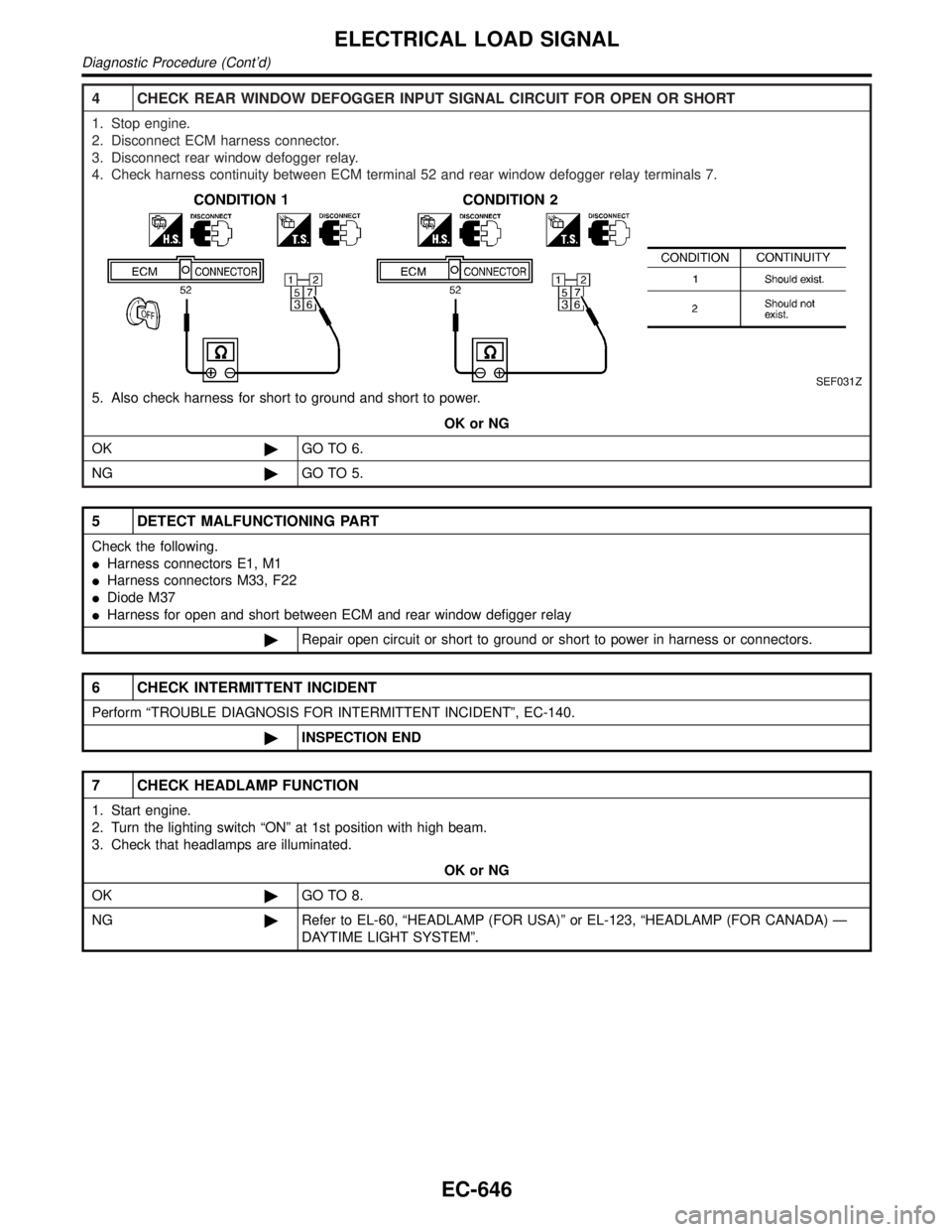
4 CHECK REAR WINDOW DEFOGGER INPUT SIGNAL CIRCUIT FOR OPEN OR SHORT
1. Stop engine.
2. Disconnect ECM harness connector.
3. Disconnect rear window defogger relay.
4. Check harness continuity between ECM terminal 52 and rear window defogger relay terminals 7.
SEF031Z
5. Also check harness for short to ground and short to power.
OK or NG
OK©GO TO 6.
NG©GO TO 5.
5 DETECT MALFUNCTIONING PART
Check the following.
IHarness connectors E1, M1
IHarness connectors M33, F22
IDiode M37
IHarness for open and short between ECM and rear window defigger relay
©Repair open circuit or short to ground or short to power in harness or connectors.
6 CHECK INTERMITTENT INCIDENT
Perform ªTROUBLE DIAGNOSIS FOR INTERMITTENT INCIDENTº, EC-140.
©INSPECTION END
7 CHECK HEADLAMP FUNCTION
1. Start engine.
2. Turn the lighting switch ªONº at 1st position with high beam.
3. Check that headlamps are illuminated.
OK or NG
OK©GO TO 8.
NG©Refer to EL-60, ªHEADLAMP (FOR USA)º or EL-123, ªHEADLAMP (FOR CANADA) Ð
DAYTIME LIGHT SYSTEMº.
ELECTRICAL LOAD SIGNAL
Diagnostic Procedure (Cont'd)
EC-646
Page 1184 of 2395

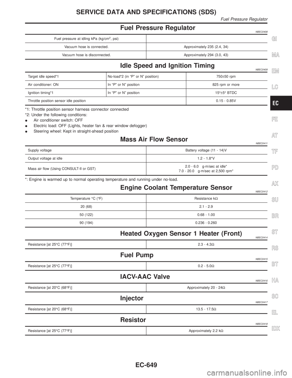
Fuel Pressure RegulatorNBEC0408
Fuel pressure at idling kPa (kg/cm2, psi)
Vacuum hose is connected. Approximately 235 (2.4, 34)
Vacuum hose is disconnected. Approximately 294 (3.0, 43)
Idle Speed and Ignition TimingNBEC0409
Target idle speed*1 No-load*2 (in ªPº or Nº position) 750±50 rpm
Air conditioner: ON In ªPº or Nº position 825 rpm or more
Ignition timing*1 In ªPº or Nº position 15ɱ5É BTDC
Throttle position sensor idle position0.15 - 0.85V
*1: Throttle position sensor harness connector connected
*2: Under the following conditions:
IAir conditioner switch: OFF
IElectric load: OFF (Lights, heater fan & rear window defogger)
ISteering wheel: Kept in straight-ahead position
Mass Air Flow SensorNBEC0411
Supply voltageBattery voltage (11 - 14)V
Output voltage at idle1.2 - 1.8*V
Mass air flow (Using CONSULT-II or GST)2.0 - 6.0 g´m/sec at idle*
7.0 - 20.0 g´m/sec at 2,500 rpm*
*: Engine is warmed up to normal operating temperature and running under no-load.
Engine Coolant Temperature SensorNBEC0412
Temperature ÉC (ÉF) Resistance kW
20 (68) 2.1 - 2.9
50 (122) 0.68 - 1.00
90 (194) 0.236 - 0.260
Heated Oxygen Sensor 1 Heater (Front)NBEC0414
Resistance [at 25ÉC (77ÉF)]2.3 - 4.3W
Fuel PumpNBEC0415
Resistance [at 25ÉC (77ÉF)]0.2 - 5.0W
IACV-AAC ValveNBEC0416
Resistance [at 20ÉC (68ÉF)]Approximately 20 - 24W
InjectorNBEC0417
Resistance [at 20ÉC (68ÉF)]13.5 - 17.5W
ResistorNBEC0418
Resistance [at 25ÉC (77ÉF)]Approximately 2.2 kW
GI
MA
EM
LC
FE
AT
TF
PD
AX
SU
BR
ST
RS
BT
HA
SC
EL
IDX
SERVICE DATA AND SPECIFICATIONS (SDS)
Fuel Pressure Regulator
EC-649
Page 1186 of 2395

ELECTRICAL SYSTEM
SECTION
EL
CONTENTS
PRECAUTIONS...............................................................4
Supplemental Restraint System (SRS)²AIR
BAG²and²SEAT BELT PRE-TENSIONER²...............4
Wiring Diagrams and Trouble Diagnosis .....................4
HARNESS CONNECTOR................................................5
Description ...................................................................5
STANDARDIZED RELAY................................................7
Description ...................................................................7
POWER SUPPLY ROUTING...........................................9
Schematic ....................................................................9
Wiring Diagram - POWER - ......................................10
Inspection...................................................................16
GROUND........................................................................17
Ground Distribution ....................................................17
COMBINATION SWITCH..............................................28
Check .........................................................................28
Replacement ..............................................................29
STEERING SWITCH......................................................30
Check .........................................................................30
HEADLAMP (FOR USA) - XENON TYPE -..................31
Component Parts and Harness Connector
Location .....................................................................31
System Description ....................................................31
Schematic ..................................................................35
Wiring Diagram - H/LAMP -.......................................36
Trouble Diagnoses.....................................................40
Bulb Replacement/Xenon Type .................................43
Aiming Adjustment .....................................................44
HEADLAMP (FOR CANADA) - DAYTIME LIGHT
SYSTEM -......................................................................46
Component Parts and Harness Connector
Location .....................................................................46
System Description ....................................................46
Schematic ..................................................................50
Wiring Diagram - DTRL - ...........................................51
Trouble Diagnoses.....................................................56
Bulb Replacement .....................................................57
Aiming Adjustment .....................................................58
HEADLAMP - HEADLAMP AIMING CONTROL -........59System Description ....................................................59
Wiring Diagram - H/AIM - ..........................................60
PARKING, LICENSE AND TAIL LAMPS.....................61
System Description ....................................................61
Schematic ..................................................................62
Wiring Diagram - TAIL/L - ..........................................63
Trouble Diagnoses.....................................................66
STOP LAMP..................................................................67
Wiring Diagram - STOP/L - .......................................67
BACK-UP LAMP............................................................69
Wiring Diagram - BACK/L - .......................................69
FRONT FOG LAMP.......................................................70
System Description ....................................................70
Wiring Diagram - F/FOG - .........................................72
Aiming Adjustment .....................................................74
TURN SIGNAL AND HAZARD WARNING LAMPS.....75
System Description ....................................................75
Wiring Diagram - TURN - ..........................................77
Trouble Diagnoses.....................................................79
Electrical Components Inspection .............................79
ILLUMINATION..............................................................80
System Description ....................................................80
Schematic ..................................................................82
Wiring Diagram - ILL - ...............................................83
INTERIOR, SPOT, VANITY MIRROR AND
LUGGAGE ROOM LAMPS...........................................88
System Description ....................................................88
Schematic ..................................................................90
Wiring Diagram - INT/L - ...........................................91
METERS AND GAUGES...............................................94
Component Parts and Harness Connector
Location .....................................................................94
System Description ....................................................94
Combination Meter ....................................................96
Schematic ..................................................................98
Wiring Diagram - METER - .......................................99
Meter/Gauge Operation and Odo/Trip Meter
Segment Check in Diagnosis Mode ........................100
Trouble Diagnoses...................................................101
GI
MA
EM
LC
EC
FE
AT
TF
PD
AX
SU
BR
ST
RS
BT
HA
SC
IDX
Page 1187 of 2395

Electrical Components Inspection ...........................108
COMPASS AND THERMOMETER............................. 110
System Description .................................................. 110
Wiring Diagram - COMPAS -................................... 111
Trouble Diagnoses................................................... 112
Calibration Procedure for Compass ........................ 113
WARNING LAMPS...................................................... 114
Schematic ................................................................ 114
Wiring Diagram - WARN - ....................................... 115
Fuel Warning Lamp Sensor Check .........................122
Electrical Components Inspection ...........................122
A/T INDICATOR...........................................................123
Wiring Diagram - AT/IND -.......................................123
WARNING CHIME.......................................................125
Component Parts and Harness Connector
Location ...................................................................125
System Description ..................................................125
Wiring Diagram - CHIME - ......................................127
Trouble Diagnoses...................................................129
FRONT WIPER AND WASHER..................................136
System Description ..................................................136
Wiring Diagram - WIPER - ......................................138
Removal and Installation .........................................139
Washer Nozzle Adjustment .....................................140
Washer Tube Layout ...............................................140
REAR WIPER AND WASHER....................................141
System Description ..................................................141
Wiring Diagram - WIP/R -........................................143
Trouble Diagnoses...................................................145
Removal and Installation .........................................145
Washer Nozzle Adjustment .....................................146
Washer Tube Layout ...............................................146
Check Valve .............................................................146
HORN...........................................................................147
Wiring Diagram - HORN - .......................................147
CIGARETTE LIGHTER................................................148
Wiring Diagram - CIGAR -.......................................148
CLOCK.........................................................................150
Wiring Diagram - CLOCK -......................................150
REAR WINDOW DEFOGGER.....................................151
Component Parts and Harness Connector
Location ...................................................................151
System Description ..................................................151
Wiring Diagram - DEF - ...........................................153
Trouble Diagnoses...................................................155
Electrical Components Inspection ...........................157
Filament Check ........................................................157
Filament Repair .......................................................158
AUDIO..........................................................................160
System Description ..................................................160
Schematic ................................................................161
Wiring Diagram - AUDIO - .......................................162Trouble Diagnoses...................................................166
Inspection.................................................................167
Wiring Diagram - REMOTE -...................................168
AUDIO ANTENNA.......................................................169
System Description ..................................................169
Wiring Diagram - P/ANT - .......................................170
Trouble Diagnoses...................................................171
Location of Antenna .................................................171
Antenna Rod Replacement .....................................171
POWER SUNROOF.....................................................173
System Description ..................................................173
Wiring Diagram - SROOF - .....................................174
Trouble Diagnoses...................................................176
DOOR MIRROR...........................................................177
Wiring Diagram - MIRROR - ...................................177
GLASS HATCH OPENER...........................................178
System Description ..................................................178
Wiring Diagram - TLID - ..........................................179
FUEL FILLER LID OPENER.......................................180
Wiring Diagram - F/LID - .........................................180
POWER SEAT.............................................................181
Wiring Diagram - SEAT - .........................................181
HEATED SEAT............................................................183
Wiring Diagram - HSEAT - ......................................183
Seatback Heating Unit .............................................185
AUTOMATIC DRIVE POSITIONER............................186
Component Parts and Harness Connector
Location ...................................................................186
System Description ..................................................187
Schematic ................................................................190
Wiring Diagram - AUT/DP - .....................................191
On Board Diagnosis ................................................196
Trouble Diagnoses...................................................198
AUTOMATIC SPEED CONTROL DEVICE (ASCD)...221
Component Parts and Harness Connector
Location ...................................................................221
System Description ..................................................222
Schematic ................................................................224
Wiring Diagram - ASCD - ........................................225
Fail-safe System ......................................................229
Trouble Diagnoses...................................................230
Electrical Component Inspection .............................239
ASCD Wire Adjustment ...........................................240
POWER WINDOW.......................................................241
System Description ..................................................241
Schematic ................................................................244
Wiring Diagram - WINDOW - ..................................245
Trouble Diagnoses...................................................250
POWER DOOR LOCK.................................................254
Component Parts and Harness Connector
Location ...................................................................254
System Description ..................................................254
CONTENTS(Cont'd)
EL-2