Page 313 of 363
�µ
�´
�´
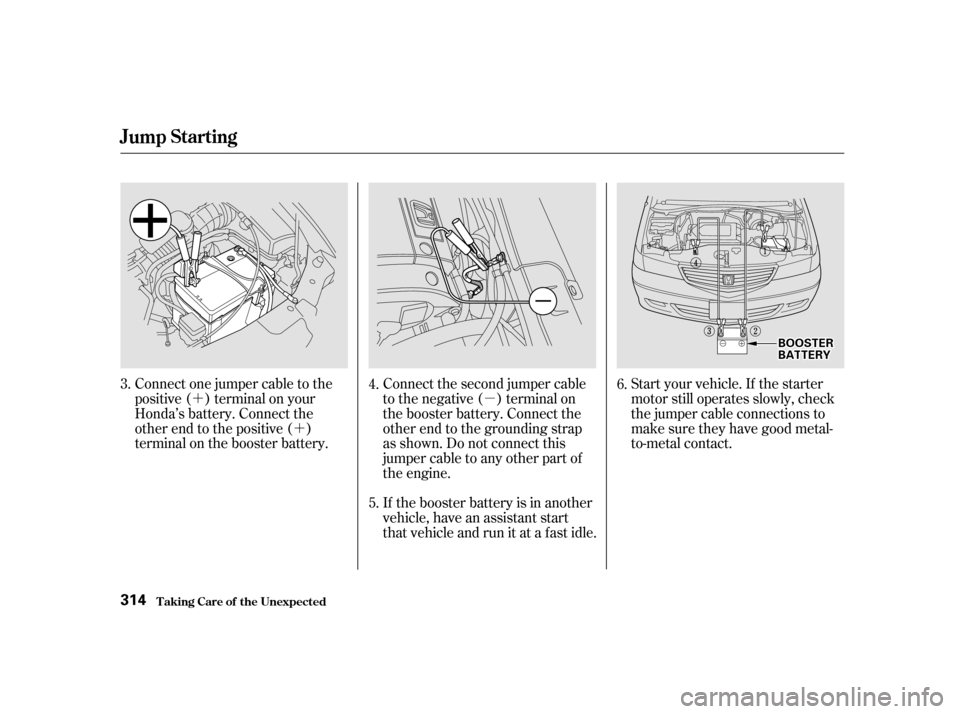
If the booster battery is in another
vehicle, have an assistant start
that vehicle and run it at a fast idle. Start your vehicle. If the starter
motor still operates slowly, check
the jumper cable connections to
make sure they have good metal-
to-metal contact.
Connect the second jumper cable
to the negative ( ) terminal on
the booster battery. Connect the
other end to the grounding strap
as shown. Do not connect this
jumper cable to any other part of
the engine.
Connect one jumper cable to the
positive ( ) terminal on your
Honda’s battery. Connect the
other end to the positive ( )
terminal on the booster battery.
5.
3.
4.6.
T aking Care of t he Unexpect ed
Jump Starting
314
BBOOOOSSTTEERRBBAATTTTEERRYY
Page 314 of 363

Once your vehicle is running,
disconnect the negative cable f rom
your vehicle, then f rom the
booster battery. Disconnect the
positive cable f rom your vehicle,
then the booster battery.The pointer of your vehicle’s
temperature gauge should stay in
the midrange under most conditions.
Itmaygohigherif youaredrivingup
a long steep hill on a very hot day. If
it climbs to the red mark, you should
determine the reason. Your vehicle can overheat for several
reasons, such as lack of coolant or a
mechanical problem. The only
indication may be the temperature
gauge climbing to or above the red
mark. Or you may see steam or
spray coming f rom under the hood.
In either case, you should take
immediate action.
Keep the ends of the jumper cables
away from each other and any metal
on the vehicle until all are
disconnected. Otherwise, you may
cause an electrical short.
7.
CONT INUED
Jump Starting, If Your Engine Overheats
If Your Engine Overheats
T aking Care of t he Unexpect ed315
Steam and spray from an
overheated engine can
seriously scald you.
Do not open the hood if steam
is coming out.
Driving with the temperature gauge
pointer at the red mark can cause
serious damage to your engine.
Page 318 of 363
This indicator should come on when
the ignition switch is ON (II), and go
out af ter the engine starts. If it
comes on brightly when the engine
is running, it indicates that the
charging system has stopped
charging the battery.By eliminating as much of the
electrical load as possible, you can
drive several miles (kilometers)
before the battery is too discharged
to keep the engine running. Drive to
a service station or garage where
you can get technical assistance.
Immediately turn of f all electrical
accessories:radio,heater,A/C,
climate control, rear def ogger, cruise
control, etc. Try not to use other
electrically-operated controls such as
the power windows. Keep the engine
running and take extra care not to
stall it. Starting the engine will
discharge the battery rapidly.
Charging System Indicator
T aking Care of t he Unexpect ed
319
CCHHAARRGGIINNGGSSYYSSTTEEMMIINNDDIICCAATTOORR
Page 320 of 363
Your vehicle has certain ‘‘readiness
codes’’ that are part of the on-board
diagnostics f or the emissions
systems. In some states, part of the
emissions testing is to make sure
these codes are set. If they are not
set, the test cannot be completed.
If your vehicele’s battery has been
disconnected or gone dead, these
codes are erased. It takes several
days of driving under various
conditions to set the codes again.If possible, do not take your car f or a
state emissions test until the
readiness codes are set. To check if
they are set, turn the ignition ON (II),
but do not start the engine. The
Malf unction Indicator Lamp will
come on f or 20 seconds. If it then
goes of f , the readiness codes are set.
If it blinks 5 times, the readiness
codes are not set. See State
Emissions Testing on pages and
. 343
344
Malf unction Indicator L amp
Readiness Codes
T aking Care of t he Unexpect ed321
Page 323 of 363
If something electrical in your
vehicle stops working, the first thing
youshouldcheckforisablownfuse.
Determine f rom the chart on pagesand , or the diagram on the
f use box lid (the diagram f or the
driver’s side interior f use box is on
the kick panel below the f use box),
which f use or f uses control that
component. Check those f uses f irst,
but check all the f uses bef ore
deciding that a blown f use is not the
cause. Replace any blown f uses and
check the component’s operation.
Turn the ignition switch to LOCK
(0). Make sure the headlights and
all other accessories are of f .
Remove the cover f rom the f use
box.
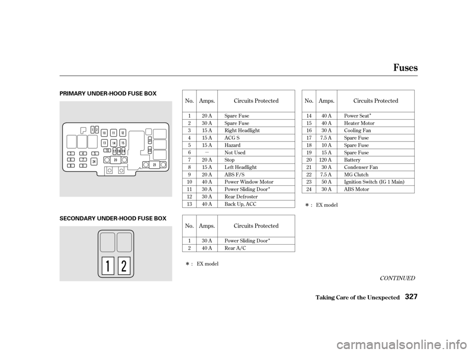
The secondary f use box is in the
engine compartment next to the
battery.
The primary under-hood f use box is
located in the back of the engine
compartment on the passenger’s side.
To open it, push the tabs as shown.
1.
2. 327 328
Fuses
T aking Care of t he Unexpect ed Checking and Replacing Fuses
324
UUNNDDEERR--HHOOOODDUUNNDDEERR--HHOOOODD
Page 326 of 363
�µ�Î
�Î �Î
�Î
�Î
CONT INUED
No. Amps. Circuits Protected No. Amps. Circuits Protected
No. Amps. Circuits Protected 1 23456789
10111213 20 A
30 A
15 A
15 A
15 A
20 A
15 A
20 A
40 A
30 A
30 A
40 A Spare Fuse
Spare Fuse
Right Headlight
ACG S
Hazard
Not Used
Stop
Lef t Headlight
ABS F/S
Power Window Motor
Power Sliding Door
Rear Defroster
Back Up, ACC 1415161718192021222324
40 A
40 A
30 A
7.5 A 10 A
15 A
120 A 30 A
7.5 A 50 A
30 A Power Seat
Heater Motor
Cooling Fan
Spare Fuse
Spare Fuse
Spare Fuse
Battery
Condenser Fan
MG Clutch
Ignition Switch (IG 1 Main)
ABS Motor
12 30 A
40 A Power Sliding Door
Rear A/C :EXmodel
:EXmodel
Fuses
T aking Care of t he Unexpect ed 327
PRIMARY UNDER-HOOD FUSE BOX
SECONDARY UNDER-HOOD FUSE BOX
Page 329 of 363
If you decide to tow your vehicle
with all f our wheels on the ground,
make sure you use a properly-
designed and attached tow bar.
Prepare the vehicle for towing as
described above, and leave the
ignition switch in Accessory (I) so
the steering wheel does not lock.
Make sure the radio and any items
plugged into the accessory power
socket are turned of f so they do not
rundownthebattery.
Emergency T owing
T aking Care of t he Unexpect ed
330
The steering system can be damaged if
the steering wheel is locked. Leave the
ignition switch in Accessory (I), and
make sure the steering wheel turns
f reely bef ore you begin towing. Trying to lif t or tow your vehicle by the
bumpers will cause serious damage.
The bumpers are not designed to
support the vehicle’s weight.
Page 334 of 363
")
�µ
�µ �µ �µ �µ �µ �µ�µ�µ�µ�µ�µ�µ �µ �µ
Specif ications
T echnical Inf ormation
335
Lights Battery
Fuses
Engine
Alignment
Tires
12 V 21 W
12 V 21/5 W
3.50 x 3.66 in (89.0 x 93.0 mm)
212 cu-in (3,471 cm
)
9.4 : 1
0.00 in (0.0 mm)
0.00 in (0.0 mm) 0°
0°30’
2°07’
P215/65R16 96T
T135/80D16 101M
35 psi (240 kPa , 2.4 kgf/cm
)
60 psi (420 kPa , 4.2 kgf/cm)
24/2.2 CP
12 V 1.8 W
12 V 8 W
12 V 21 W
12 V 3 CP
2CP
21 CP (18 W)
4CP
10 W
12 V
12 V
12 V
12 V
12 V
60/55 W (HB2)
12 V
65 AH/20 HR
52 AH/5 HR
12 V
12 V
Headlights
Front turn signal/parking/side
marker lights
Rear turn signal lights
Stop/Taillights/Rear side
marker lights
Taillights
Back-up lights
License plate light
High-mount brake light
Individual map lights
Cargo area light
Vanity mirror lights
Capacity
Interior
Under-hood Type
BorexStroke
Displacement
Compression ratio
Spark plugs
Toe-in
CamberCaster Size
Pressure
See page 328 or the fuse label
attached to the dashboard.
See page 328 or the fuse label
attached to the inside of the fuse
box door under the dashboard.
See page 327 or the fuse box
cover. See spark plug maintenance sec-
tion page 266 .
High/Low
Front/Rear
Spare
Front/Rear
Spare
FrontRear
FrontRear
Front
FrontRear
Driver’s side
Passenger’s side
Water cooled 4-stroke SOHC VTEC, 6-cylinder, gasoline engine
, and go
out af ter the engine starts. If it
comes on brightly when the engine
is running, it indicates that the
charging system has s")