Page 7 of 288
Vehicle Symbol Glossary
Child Safety Door
Lock/Unlock
Interior Luggage
Compartment Release
Symbol
Panic AlarmEngine Oil
Engine CoolantEngine Coolant
Temperature
Do Not Open When HotBattery
Avoid Smoking, Flames,
or SparksBattery Acid
Explosive GasFan Warning
Power Steering FluidMaintain Correct Fluid
LevelMAX
MIN
Emission SystemEngine Air Filter
Passenger Compartment
Air FilterJack
Check fuel cap
Introduction
7
Page 14 of 288
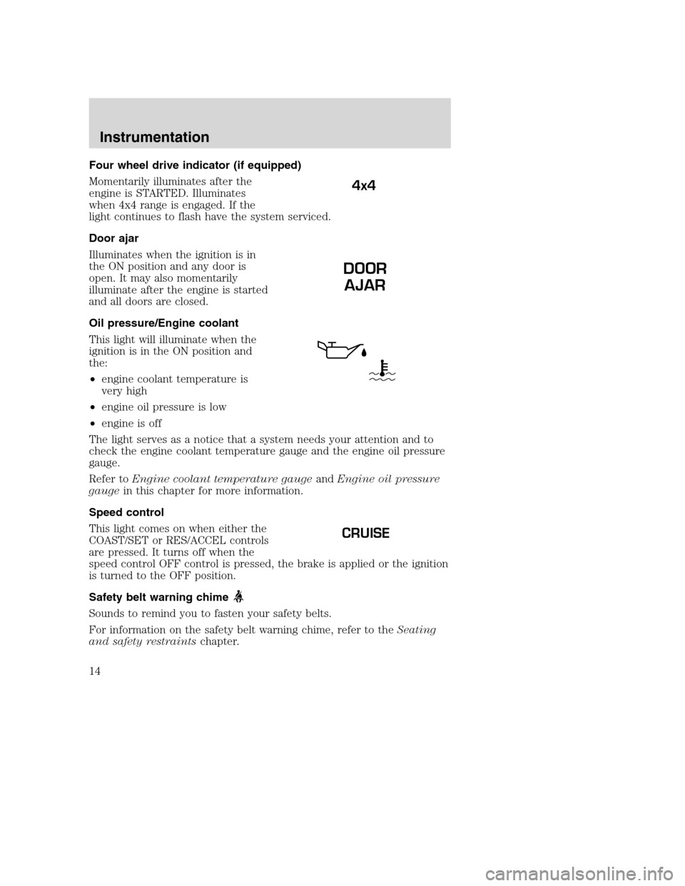
Four wheel drive indicator (if equipped)
Momentarily illuminates after the
engine is STARTED. Illuminates
when 4x4 range is engaged. If the
light continues to flash have the system serviced.
Door ajar
Illuminates when the ignition is in
the ON position and any door is
open. It may also momentarily
illuminate after the engine is started
and all doors are closed.
Oil pressure/Engine coolant
This light will illuminate when the
ignition is in the ON position and
the:
•engine coolant temperature is
very high
•engine oil pressure is low
•engine is off
The light serves as a notice that a system needs your attention and to
check the engine coolant temperature gauge and the engine oil pressure
gauge.
Refer toEngine coolant temperature gaugeandEngine oil pressure
gaugein this chapter for more information.
Speed control
This light comes on when either the
COAST/SET or RES/ACCEL controls
are pressed. It turns off when the
speed control OFF control is pressed, the brake is applied or the ignition
is turned to the OFF position.
Safety belt warning chime
Sounds to remind you to fasten your safety belts.
For information on the safety belt warning chime, refer to theSeating
and safety restraintschapter.
4x4
DOOR
AJAR
CRUISE
Instrumentation
14
Page 19 of 288
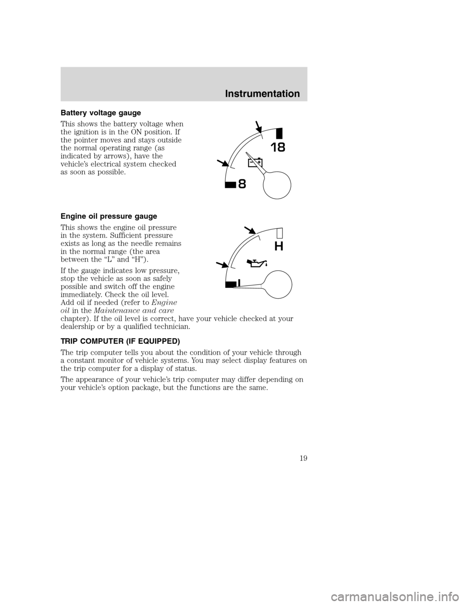
Battery voltage gauge
This shows the battery voltage when
the ignition is in the ON position. If
the pointer moves and stays outside
the normal operating range (as
indicated by arrows), have the
vehicle’s electrical system checked
as soon as possible.
Engine oil pressure gauge
This shows the engine oil pressure
in the system. Sufficient pressure
exists as long as the needle remains
in the normal range (the area
between the “L” and “H”).
If the gauge indicates low pressure,
stop the vehicle as soon as safely
possible and switch off the engine
immediately. Check the oil level.
Add oil if needed (refer toEngine
oilin theMaintenance and care
chapter). If the oil level is correct, have your vehicle checked at your
dealership or by a qualified technician.
TRIP COMPUTER (IF EQUIPPED)
The trip computer tells you about the condition of your vehicle through
a constant monitor of vehicle systems. You may select display features on
the trip computer for a display of status.
The appearance of your vehicle’s trip computer may differ depending on
your vehicle’s option package, but the functions are the same.
818
L
H
Instrumentation
19
Page 164 of 288
•The Front Axle Accessory Reserve Capacity and the Total Accessory
Reserve Capacity listed on the bottom right of the Safety Compliance
Certification Label will determine whether or not the addition of a
snowplow will overload your vehicle.
•The weight of the snowplow and supporting components distributed to
the front axle must not exceed the front accessory reserve capacity.
•The total weight of the snowplow and aftermarket equipment must
not exceed the Total Accessory Reserve Capacity.
•The weight of the installed snowplow and aftermarket equipment must
not load the vehicle beyond the GAWR (front/rear) and GVWR listed
on the Safety Compliance Certification Label.
•The total weight of the snowplow and aftermarket equipment must be
considered part of the payload and must not exceed the Gross
Combined Weight Rating (GCWR) for towing.
•Federal and most local regulations require additional exterior lamps
for snowplow-equipped vehicles. Consult your dealer for additional
information.
•After installing a snowplow to the vehicle, ensure the vehicle’s front
toe alignment and front ride height are within specification (reset if
required). These specifications are located in the vehicle’s Workshop
Manual. Adherence to the toe, tire pressures and ride height
specification is important for proper tire wear, ride, handling and
headlight aim. Also, maintain the engine oil and transmission fluid
change intervals following the severe duty schedule.
Do not exceed the GVWR or the GAWR specified on the
certification label.
Removing snowplow
Read the following instructions before removing a snowplow:
•After removing a snowplow from the vehicle, ensure the vehicle’s front
toe alignment and front ride height are within specification (reset if
required). These specifications are located in the vehicle’s Workshop
Manual. Adherence to the toe and ride height specification is
important for proper tire wear, ride, handling and headlight aim.
Driving
164
Page 173 of 288
Fuse/Relay
LocationFuse Amp
RatingPassenger Compartment Fuse Panel
Description
11 30A Wiper Motor, Wiper Run/Park Relay Coil,
Wiper Hi/LO Relay Coil, Washer Pump
Relay Coil
12 15A Horn
13 20A Stop Lamps, Center High-mount Stop
Lamp, Trailer Tow Stop Lamp, Speed
Control
14 10A Dome Lamp, Cargo Lamp, Courtesy
Lamps, Running Board Lamps
15 5A Stop Lamp Switch (Logic): Generic
Electronic Module (GEM), Powertrain
Control Module (PCM), Four Wheel
Anti-lock Brake System (4WABS) Module,
Brake Shift Interlock, Cluster and PCM
Keep Alive Memory
16 15A Instrument Cluster, Hi-beam Headlamps
17 — Not Used
18 5A Audio
19 10A Auxiliary Powertrain Control Module
(APCM) (Diesel only), Instrument Cluster,
GEM Module, Overdrive Cancel Switch,
Idle Validation Switch (Diesel only),
Overhead Console, Diesel PCM via Clutch
20 15A Starter Motor Relay Coil, Clutch Switch
21 — Not Used
22 10A Passenger Air Bag Activation/Deactivation
Switch, Blower Motor Relay Coil
23 10A Air Bag Module
24 10A A/C Clutch, Blend Door Actuator, Trailer
Tow Battery Charge Relay Coil, Four
Wheel Anti-Lock Brake System (4WABS),
Turn Signal
25 — Not Used
Roadside emergencies
173
Page 174 of 288
Fuse/Relay
LocationFuse Amp
RatingPassenger Compartment Fuse Panel
Description
26 — Not Used
27 10A Ignition Run Power Feed (Customer
Access)
28 15A Brake Shift Interlock, DRL Relay Coil,
Speed Control Module, Backup Lamps,
Trailer Tow Backup Lamp Relay Coil,
Electronic Shift On The Fly Hub Lock
Solenoid, Vacuum Pump Motor
29 5A Instrument Cluster (Charge and Airbag
Warning Lamps)
30 30A PCM Relay Coil, Ignition Coil (Gasoline
only), Fuel Heater (Diesel only),
Wastegate Solenoid (Diesel only), Injector
Driver Module Relay Coil (Diesel only)
31 5A Fog Lamp Switch
Relay 1 — Interior Lamp Relay
Relay 2 — Not Used
Relay 3 — Horn
Relay 4 — Power Window One Touch Down Relay
Relay 5 — Accessory Delay Relay
Roadside emergencies
174
Page 176 of 288
The high-current fuses and relays are coded as follows.
Fuse/Relay
LocationFuse Amp
RatingPower Distribution Box Description
1 7.5A * Trailer Tow Left Stop/Turn Lamp
2 10A* Washer Pump
3 7.5A* Trailer Tow Right Stop/Turn Lamp
4 20A* Trailer Tow Backup Lamps, Trailer Tow
Park Lamps
5 20A*
(Gasoline only)
5A*
(Diesel only)
Gasoline only-PCM, Fuel Pump Relay
Coil, Mass Air Flow Sensor, Fuel Injectors
Diesel only-Dual Alternator�A�Field
6 10A* Gasoline only-A/C (CASS)
Diesel only-Single or Dual Alternator�A�
Field, Regulator
19 29
18 2830
31
32
33
34
35
37 36 17 27
16 26
15 25
14 24
13
11 12
910
78
56
34
1223
22
21
20
Roadside emergencies
176
Page 177 of 288
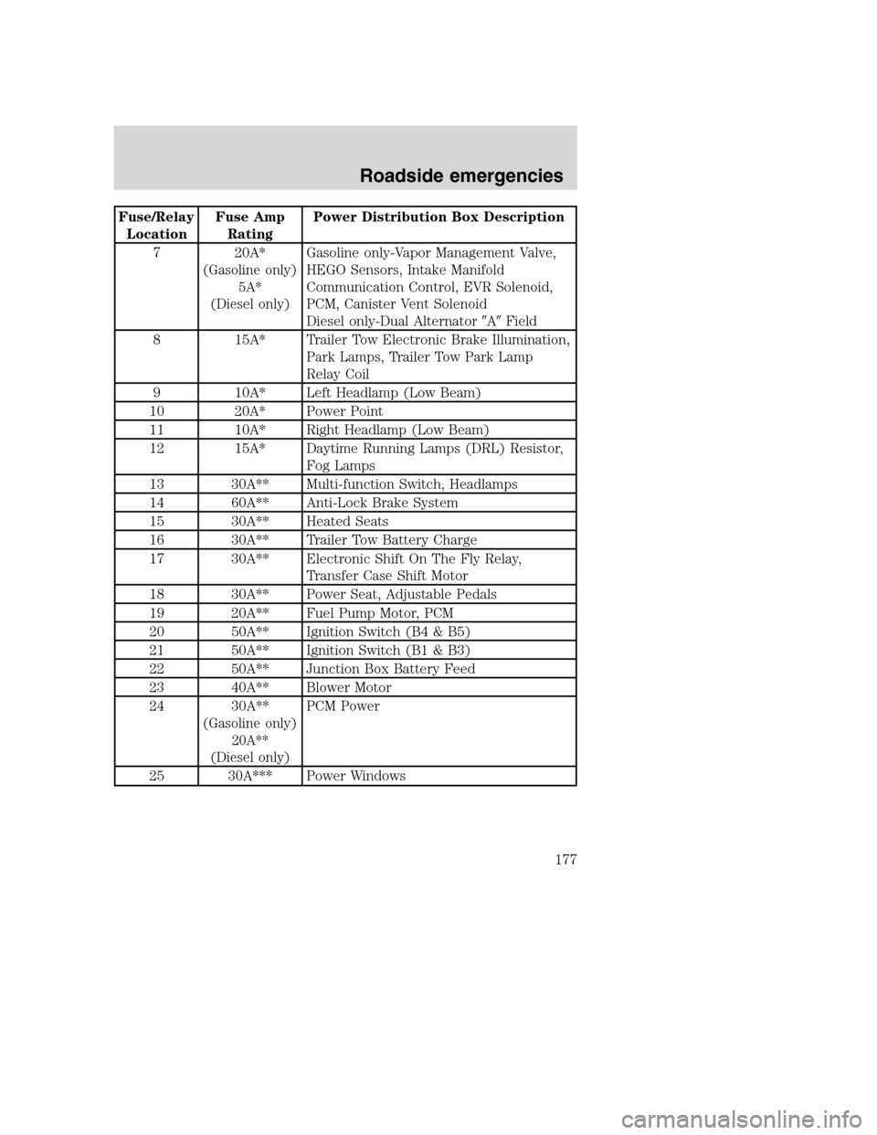
Fuse/Relay
LocationFuse Amp
RatingPower Distribution Box Description
7 20A*
(Gasoline only)
5A*
(Diesel only)
Gasoline only-Vapor Management Valve,
HEGO Sensors, Intake Manifold
Communication Control, EVR Solenoid,
PCM, Canister Vent Solenoid
Diesel only-Dual Alternator�A�Field
8 15A* Trailer Tow Electronic Brake Illumination,
Park Lamps, Trailer Tow Park Lamp
Relay Coil
9 10A* Left Headlamp (Low Beam)
10 20A* Power Point
11 10A* Right Headlamp (Low Beam)
12 15A* Daytime Running Lamps (DRL) Resistor,
Fog Lamps
13 30A** Multi-function Switch, Headlamps
14 60A** Anti-Lock Brake System
15 30A** Heated Seats
16 30A** Trailer Tow Battery Charge
17 30A** Electronic Shift On The Fly Relay,
Transfer Case Shift Motor
18 30A** Power Seat, Adjustable Pedals
19 20A** Fuel Pump Motor, PCM
20 50A** Ignition Switch (B4 & B5)
21 50A** Ignition Switch (B1 & B3)
22 50A** Junction Box Battery Feed
23 40A** Blower Motor
24 30A**
(Gasoline only)
20A**
(Diesel only)
PCM Power
25 30A*** Power Windows
Roadside emergencies
177