Page 178 of 288
Fuse/Relay
LocationFuse Amp
RatingPower Distribution Box Description
26 20A** If equipped with Remote Keyless
Entry-Driver Door Unlock Relay Coil, All
Door Unlock Relay Coil, All Door Lock
Relay Coil, Park Lamp Flash Relay, If not
equipped with Remote Keyless
Entry-Power Door Lock Motors
27 - (Gasoline
only)
30A**
(Diesel only)Gasoline only-Not Used
Diesel only-Injector Driver Module
28 30A** Trailer Tow Electronic Brake Controller
29 20A** Radio
30 -- PCM Power Relay
31 -- Blower Motor Relay
32 -- A/C CASS (Gasoline only), Injector Driver
Module Power Relay (Diesel only)
33 -- Washer Pump Relay
34 -- Windshield Wiper Park/Run Relay
35 -- Windshield Wiper HI/LO Relay
36 -- A/C Clutch Diode
37 -- PCM Diode
38 -- Trailer Tow Backup Lamp Relay
39 -- Trailer Tow Battery Charge Relay
40 -- Electronic Shift On The Fly Relay #1
41 — Electronic Shift On The Fly Relay #2
* Mini Fuses ** Maxi Fuses ***Circuit Breaker
Roadside emergencies
178
Page 190 of 288
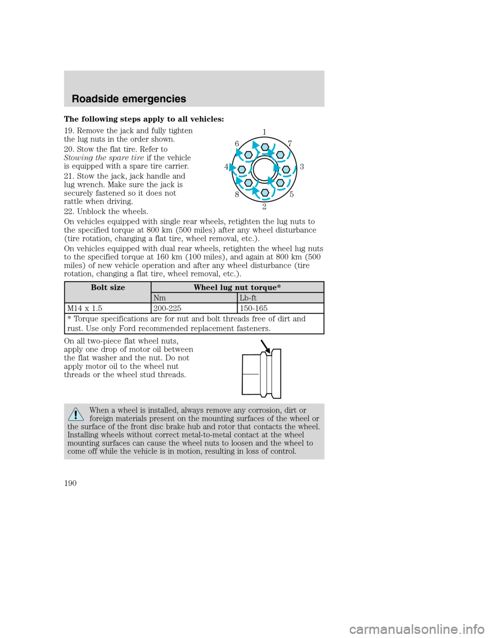
The following steps apply to all vehicles:
19.
Remove the jack and fully tighten
the lug nuts in the order shown.
20.Stow the flat tire. Refer to
Stowing the spare tireif the vehicle
is equipped with a spare tire carrier.
21. Stow the jack, jack handle and
lug wrench. Make sure the jack is
securely fastened so it does not
rattle when driving.
22. Unblock the wheels.
On vehicles equipped with single rear wheels, retighten the lug nuts to
the specified torque at 800 km (500 miles) after any wheel disturbance
(tire rotation, changing a flat tire, wheel removal, etc.).
On vehicles equipped with dual rear wheels, retighten the wheel lug nuts
to the specified torque at 160 km (100 miles), and again at 800 km (500
miles) of new vehicle operation and after any wheel disturbance (tire
rotation, changing a flat tire, wheel removal, etc.).
Bolt size Wheel lug nut torque*
Nm Lb-ft
M14 x 1.5 200-225 150-165
* Torque specifications are for nut and bolt threads free of dirt and
rust. Use only Ford recommended replacement fasteners.
On all two-piece flat wheel nuts,
apply one drop of motor oil between
the flat washer and the nut. Do not
apply motor oil to the wheel nut
threads or the wheel stud threads.
When a wheel is installed, always remove any corrosion, dirt or
foreign materials present on the mounting surfaces of the wheel or
the surface of the front disc brake hub and rotor that contacts the wheel.
Installing wheels without correct metal-to-metal contact at the wheel
mounting surfaces can cause the wheel nuts to loosen and the wheel to
come off while the vehicle is in motion, resulting in loss of control.
1
3 4
27 6
5 8
Roadside emergencies
190
Page 200 of 288
IDENTIFYING COMPONENTS IN THE ENGINE COMPARTMENT
5.4L V8/6.8L V10 gasoline engines
Refer to the7.3 Liter Power Stroke Direct Injection Turbo Diesel
Owner’s Guide Supplementfor diesel engine component locations.
1. Engine oil dipstick
2. Clutch fluid reservoir (manual transmission)
3. Brake fluid reservoir
4. Power distribution box
5. Power steering fluid reservoir
6. Air filter assembly
7. Engine coolant reservoir
8. Windshield washer fluid reservoir
9. Battery
10. Engine oil filler cap
11. Transmission fluid dipstick (automatic transmission)
910111234
867
5
Maintenance and care
200
Page 201 of 288
ENGINE OIL
Checking the engine oil
Refer to the scheduled maintenance guide for the appropriate intervals
for checking the engine oil.
1. Make sure the vehicle is on level ground.
2. Turn the engine off and wait a few minutes for the oil to drain into the
oil pan.
3. Set the parking brake and ensure the gearshift is securely latched in P
(Park) (automatic transmission) or 1 (First) (manual transmission).
4. Open the hood. Protect yourself from engine heat.
5. Locate and carefully remove the
engine oil level indicator (dipstick).
6. Wipe the indicator clean. Insert the indicator fully, then remove it
again.
•If the oil level isbetween the MIN and MAX marks,the oil level is
acceptable.DO NOT ADD OIL.
MIN MAX
Maintenance and care
201
Page 202 of 288
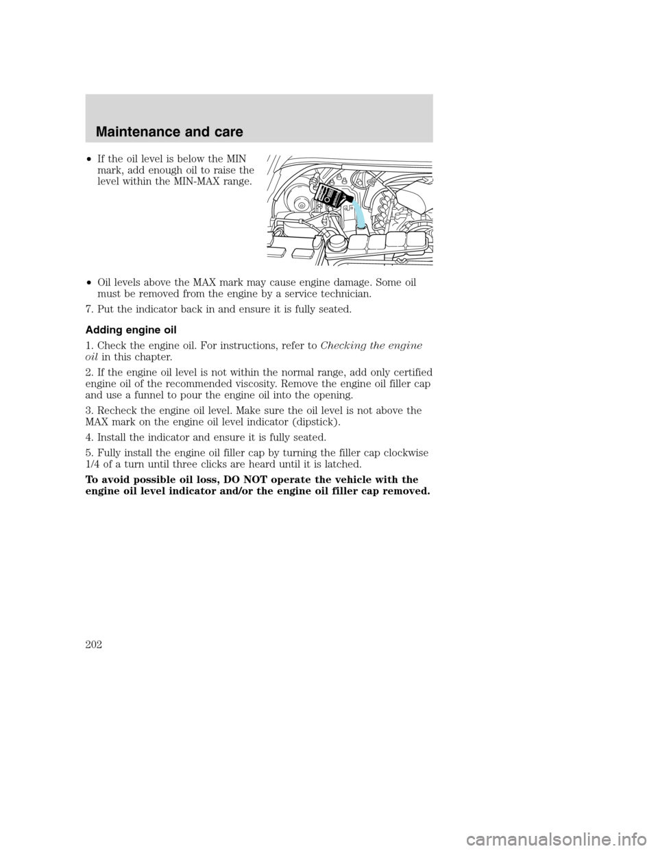
•If the oil level is below the MIN
mark, add enough oil to raise the
level within the MIN-MAX range.
•Oil levels above the MAX mark may cause engine damage. Some oil
must be removed from the engine by a service technician.
7. Put the indicator back in and ensure it is fully seated.
Adding engine oil
1. Check the engine oil. For instructions, refer toChecking the engine
oilin this chapter.
2. If the engine oil level is not within the normal range, add only certified
engine oil of the recommended viscosity. Remove the engine oil filler cap
and use a funnel to pour the engine oil into the opening.
3. Recheck the engine oil level. Make sure the oil level is not above the
MAX mark on the engine oil level indicator (dipstick).
4. Install the indicator and ensure it is fully seated.
5. Fully install the engine oil filler cap by turning the filler cap clockwise
1/4 of a turn until three clicks are heard until it is latched.
To avoid possible oil loss, DO NOT operate the vehicle with the
engine oil level indicator and/or the engine oil filler cap removed.
Maintenance and care
202
Page 203 of 288
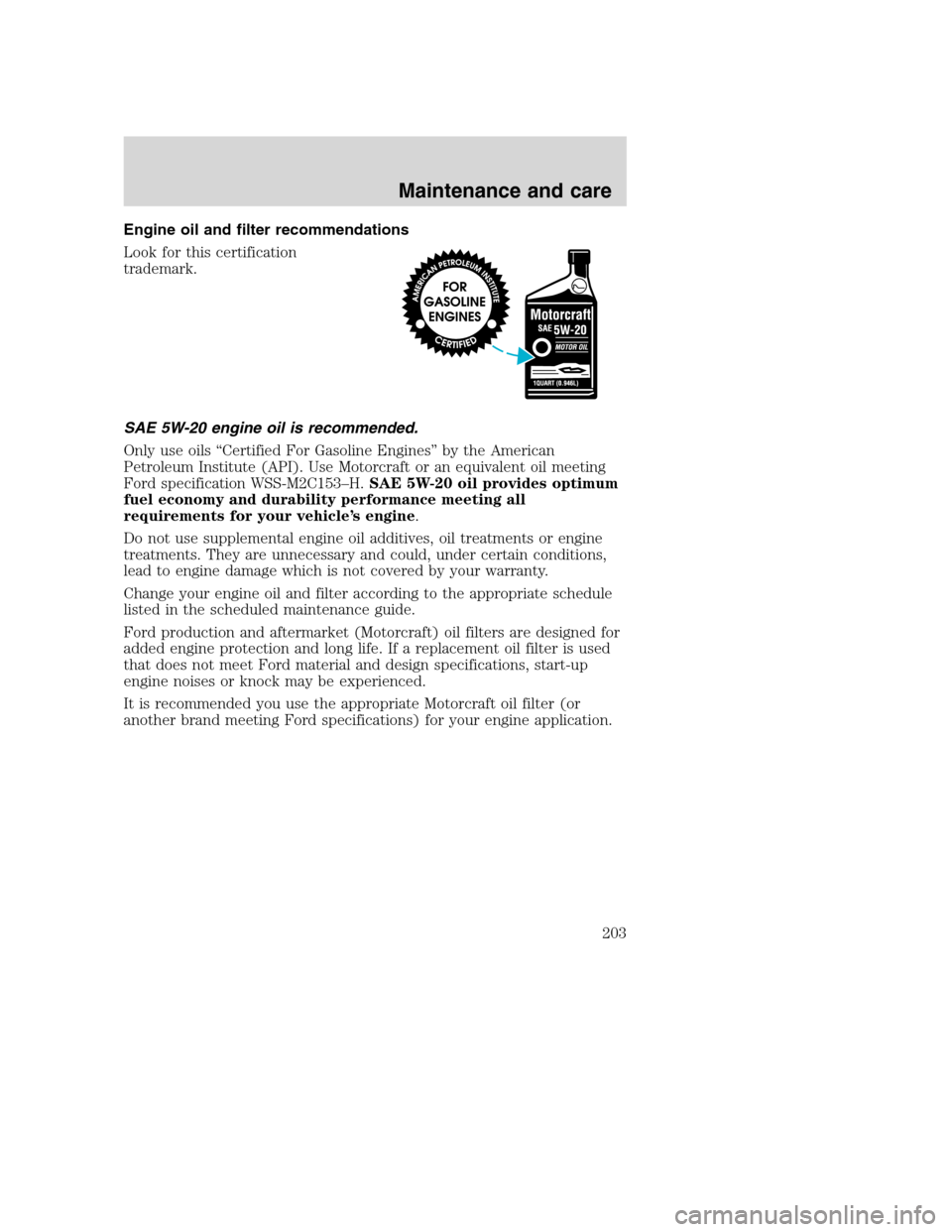
Engine oil and filter recommendations
Look for this certification
trademark.
SAE 5W-20 engine oil is recommended.
Only use oils “Certified For Gasoline Engines” by the American
Petroleum Institute (API). Use Motorcraft or an equivalent oil meeting
Ford specification WSS-M2C153–H.SAE 5W-20 oil provides optimum
fuel economy and durability performance meeting all
requirements for your vehicle’s engine.
Do not use supplemental engine oil additives, oil treatments or engine
treatments. They are unnecessary and could, under certain conditions,
lead to engine damage which is not covered by your warranty.
Change your engine oil and filter according to the appropriate schedule
listed in the scheduled maintenance guide.
Ford production and aftermarket (Motorcraft) oil filters are designed for
added engine protection and long life. If a replacement oil filter is used
that does not meet Ford material and design specifications, start-up
engine noises or knock may be experienced.
It is recommended you use the appropriate Motorcraft oil filter (or
another brand meeting Ford specifications) for your engine application.
Maintenance and care
203
Page 207 of 288
Your vehicle was factory-filled with a 50/50 engine coolant and water
concentration. If the concentration of coolant falls below 40% or above
60%, the engine parts could become damaged or not work properly.A
50–50 mixture of coolant and water provides the following:
•Freeze protection down to -36° C (-34° F).
•Boiling protection up to 129° C (265° F).
•Protection against rust and other forms of corrosion.
•Enables calibrated gauges to work properly.
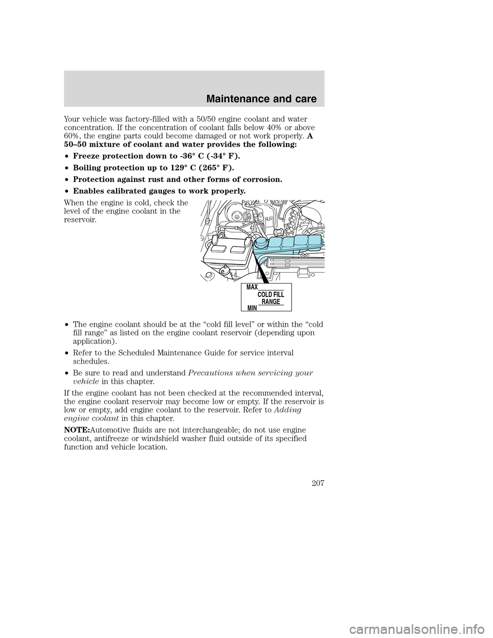
When the engine is cold, check the
level of the engine coolant in the
reservoir.
•The engine coolant should be at the “cold fill level” or within the “cold
fill range” as listed on the engine coolant reservoir (depending upon
application).
•Refer to the Scheduled Maintenance Guide for service interval
schedules.
•Be sure to read and understandPrecautions when servicing your
vehiclein this chapter.
If the engine coolant has not been checked at the recommended interval,
the engine coolant reservoir may become low or empty. If the reservoir is
low or empty, add engine coolant to the reservoir. Refer toAdding
engine coolantin this chapter.
NOTE:Automotive fluids are not interchangeable; do not use engine
coolant, antifreeze or windshield washer fluid outside of its specified
function and vehicle location.
COLD FILL
RANGEMAX
MIN
Maintenance and care
207
Page 238 of 288
Handle a halogen headlamp bulb carefully and keep out of
children’s reach. Grasp the bulb only by its plastic base and do
not touch the glass. The oil from your hand could cause the bulb to
break the next time the headlamps are operated.
6. Insert the glass end of the new bulb into the headlamp assembly.
When the grooves in the plastic base are aligned, push the bulb into the
lamp assembly until the plastic base contacts the rear of the lamp
assembly.
7. Install bulb retaining ring over the plastic base and lock the ring into
the socket by turning it clockwise until you feel a “stop.”
8. Connect the electrical connector into the rear of the plastic base until
it “snaps.”
Replacing headlamp bulbs (sealed beam)
To remove the headlamp bulb:
1. Make sure headlamp switch is in OFF position.
2. Open the hood.
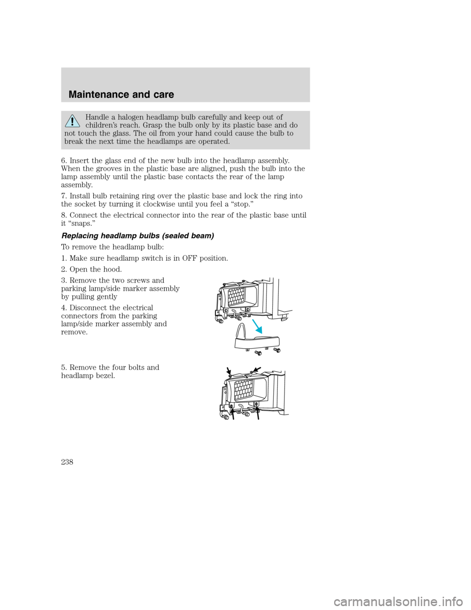
3. Remove the two screws and
parking lamp/side marker assembly
by pulling gently
4. Disconnect the electrical
connectors from the parking
lamp/side marker assembly and
remove.
5. Remove the four bolts and
headlamp bezel.
Maintenance and care
238