Page 213 of 288
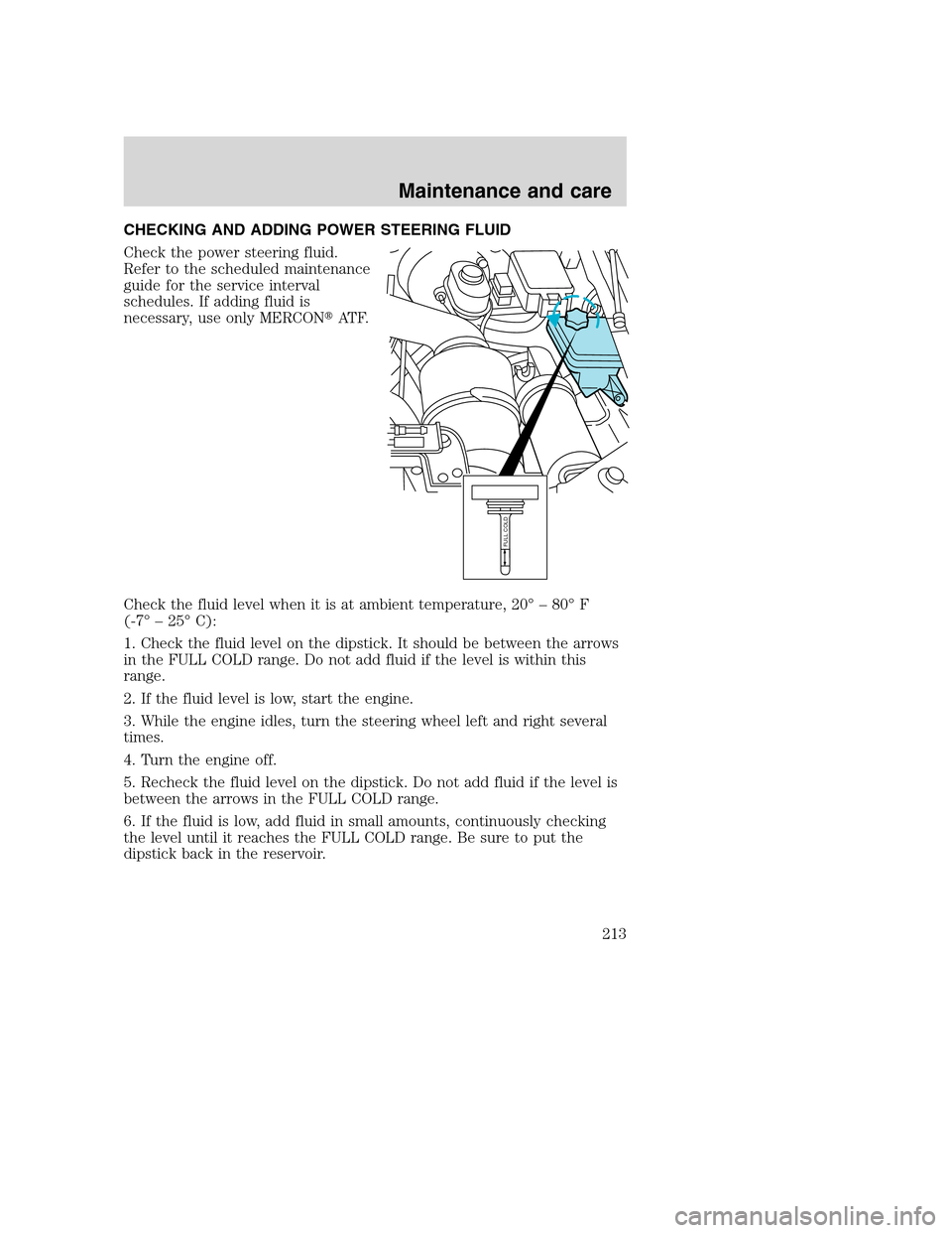
CHECKING AND ADDING POWER STEERING FLUID
Check the power steering fluid.
Refer to the scheduled maintenance
guide for the service interval
schedules. If adding fluid is
necessary, use only MERCON�AT F.
Check the fluid level when it is at ambient temperature, 20° – 80° F
(-7° – 25° C):
1. Check the fluid level on the dipstick. It should be between the arrows
in the FULL COLD range. Do not add fluid if the level is within this
range.
2. If the fluid level is low, start the engine.
3. While the engine idles, turn the steering wheel left and right several
times.
4. Turn the engine off.
5. Recheck the fluid level on the dipstick. Do not add fluid if the level is
between the arrows in the FULL COLD range.
6. If the fluid is low, add fluid in small amounts, continuously checking
the level until it reaches the FULL COLD range. Be sure to put the
dipstick back in the reservoir.
FULL COLD
Maintenance and care
213
Page 232 of 288

ESSENTIALS OF GOOD FUEL ECONOMY
Measuring techniques
Your best source of information about actual fuel economy is you, the
driver. You must gather information as accurately and consistently as
possible. Fuel expense, frequency of fillups or fuel gauge readings are
NOT accurate as a measure of fuel economy. We do not recommend
taking fuel economy measurements during the first 1 600 km (1 000
miles) of driving (engine break-in period). You will get a more accurate
measurement after 3 000 km–5 000 km (2 000 miles-3 000 miles).
Filling the tank
The advertised fuel capacity of the fuel tank on your vehicle is equal to
the rated refill capacity of the fuel tank as listed in theRefill capacities
section ofthe Capacities and specificationschapter.
The advertised capacity is the amount of the indicated capacity and the
empty reserve combined. Indicated capacity is the difference in the
amount of fuel in a full tank and a tank when the fuel gauge indicates
empty. Empty reserve is the small amount of fuel remaining in the fuel
tank after the fuel gauge indicates empty.
The amount of usable fuel in the empty reserve varies and should
not be relied upon to increase driving range. When refueling your
vehicle after the fuel gauge indicates empty, you might not be
able to refuel the full amount of the advertised capacity of the
fuel tank due to the empty reserve still present in the tank.
For consistent results when filling the fuel tank:
•Turn the engine/ignition switch to the off position prior to refueling,
an error in the reading will result if the engine is left running.
•Use the same filling rate setting (low — medium — high) each time
the tank is filled.
•Allow no more than 2 automatic click-offs when filling.
•Always use fuel with the recommended octane rating.
•Use a known quality gasoline, preferably a national brand.
•Use the same side of the same pump and have the vehicle facing the
same direction each time you fill up.
•Have the vehicle loading and distribution the same every time.
Your results will be most accurate if your filling method is consistent.
Maintenance and care
232
Page 233 of 288
.
2. Each time you fill the tank, record the amount of fuel added (in liters
o")
Calculating fuel economy
1. Fill the fuel tank completely and record the initial odometer reading
(in kilometers or miles).
2. Each time you fill the tank, record the amount of fuel added (in liters
or gallons).
3. After at least three to five tank fill-ups, fill the fuel tank and record
the current odometer reading.
4. Subtract your initial odometer reading from the current odometer
reading.
5. Follow one of the simple calculations in order to determine fuel
economy:
Multiply liters used by 100, then divide by total kilometers
traveled.
Divide total miles traveled by total gallons used.
Keep a record for at least one month and record the type of driving (city
or highway). This will provide an accurate estimate of the vehicle’s fuel
economy under current driving conditions. Additionally, keeping records
during summer and winter will show how temperature impacts fuel
economy. In general, lower temperatures give lower fuel economy.
Driving style — good driving and fuel economy habits
Give consideration to the lists that follow and you may be able to change
a number of variables and improve your fuel economy.
Habits
•Smooth, moderate operation can yield up to 10% savings in fuel.
•Steady speeds without stopping will usually give the best fuel
economy.
•Idling for long periods of time (greater than one minute) may waste
fuel.
•Anticipate stopping; slowing down may eliminate the need to stop.
•Sudden or hard accelerations may reduce fuel economy.
•Slow down gradually.
Maintenance and care
233
Page 237 of 288

Allow the vehicle to sit for at least eight hours without starting the
engine. Then, start the engine and complete the above driving cycle. The
engine must warm up to its normal operating temperature. Once started,
do not turn off the engine until the above driving cycle is complete.
BULBS
Replacing exterior bulbs
Check the operation of the following lamps frequently:
•Headlamps
•High-mount brakelamp
•Brakelamps
•Turn signals
•License plate lamp
•Tail lamps
•Back-up lamps
Do not remove lamp bulbs unless they can be replaced immediately with
new ones. If a bulb is removed for an extended period of time,
contaminants may enter the lamp housings and affect lamp performance.
Replacing headlamp bulbs (aerodynamic)
1. Make sure that the headlamp control is in the OFF position.
2. Open the hood.
3. Disconnect the electrical connector from the bulb by pulling rearward.
4. Remove bulb retainer ring by
turning it counterclockwise, then
slide the ring off the plastic base.
5. Without turning, carefully pull
bulb out of headlamp assembly.
Maintenance and care
237
Page 241 of 288
Replacing brake/tail/backup lamp bulbs — F450/F550 only
The brake/tail/backup lamp bulbs
are located in the same portion of
the tail lamp assembly. Follow the
same steps to replace either bulb:
1. Remove the four screws and the
lamp lens from lamp assembly.
2. Carefully pull the bulb straight
out of the socket and push in the
new bulb.
3. Install the lens on the lamp
assembly with the four screws.
Replacing cargo lamp and high-mount brakelamp bulbs
To remove the lamp assembly:
1. Remove the two screws and lamp
assembly from vehicle as wiring
permits.
2. Remove the bulb socket by
rotating counterclockwise and
pulling it out of the lamp assembly.
3. Pull the bulb straight out of the
socket and push in the new bulb.
To install the brakelamp assembly:
1. Install the bulb into the lamp
assembly and rotate clockwise.
2. Install the lamp assembly on the vehicle with two screws.
Maintenance and care
241
Page 243 of 288

Using the right bulbs
Replacement bulbs are specified in the chart below. Headlamp bulbs
must be marked with an authorized “D.O.T.” for North America and an
“E” for Europe to assure lamp performance, light brightness and pattern
and safe visibility. The correct bulbs will not damage the lamp assembly
or void the lamp assembly warranty and will provide quality bulb burn
time.
Function Number of
bulbsTrade number
Headlamps (aerodynamic) 2 9007
Headlamps (sealed beam) 2 H6054
Park/turn 2 3157
Sidemarker 2 194
Tail/stop/turn/sidemarker 2 3157 K
Backup 2 3156K
High-mount stoplamp 1 921
Foglamp 2 899
License plate lamp 2 168
Cargo lamp 2 906
Roofmarker 5 194
Rear fender clearance 4
(a)
Interior visor lamp (if equipped) 4 194
Rear identification 3 194
All replacement bulbs are clear in color except where noted.
To replace all instrument panel lights - see your dealer
(a)Replace entire lamp assembly; bulb is not serviceable.
AIMING THE HEADLAMPS
The headlamps on your vehicle are properly aimed at the assembly plant.
If your vehicle has been in an accident the alignment of your headlamps
should be checked by a qualified service technician.
CLEANING AND CARING FOR YOUR VEHICLE
Refer to the Customer Assistance chapter for a list of Ford-approved
cleaners, polishes and waxes.
Maintenance and care
243
Page 251 of 288
71.9L (19.0
gallons)
Right side
saddle mounted
tank (optional
on Chassis Cab)87.1L (23.0
gallons)
Short box")
FluidFord Part
NameApplication Capacity
Fuel tank N/A Mid-ship tank
(optional on
Chassis Cab)71.9L (19.0
gallons)
Right side
saddle mounted
tank (optional
on Chassis Cab)87.1L (23.0
gallons)
Short box 109.8L (29.0
gallons)
Long box 143.9L (38.0
gallons)
Aft axle 151.4L (40.0
gallons)
Power steering
fluidMotorcraft
MERCON�AT FAll Fill to line on
reservoir
Transfer case
fluidMotorcraft
MERCON�AT F4x4 vehicles 1.9L (2.0
quarts)
Transmission
fluid
4Synthetic
MERCON�AT F5-speed manual 3.2L (3.4
quarts)5
Motorcraft
MERCON�AT F6-speed manual 5.5L (5.8
quarts)5
Automatic 16.7L (17.7
quarts)6
Windshield
washer fluidUltra-Clear
Windshield
Washer
ConcentrateAll 4.0L (4.25
quarts)
1Your vehicle’s rear axle(s) may be filled with a synthetic lubricant that
may require a lubricant change. Refer to the scheduled maintenance
guide. Axle lubricant quantities should not need to be checked unless a
leak is suspected, service is required or the axle assembly has been
submerged in water. The axle lubricant should be changed any time the
rear axle has been submerged in water.
Capacities and specifications
251
Page 252 of 288
 of Additive Friction Modifier C8AZ-19B546-A or
equivalent meeting Ford Specification EST-M2C118-A for complete refill
of Traction-Lok axles.
3Add the coolant type originally equipp")
2Add 236 ml (8 oz.) of Additive Friction Modifier C8AZ-19B546-A or
equivalent meeting Ford Specification EST-M2C118-A for complete refill
of Traction-Lok axles.
3Add the coolant type originally equipped in your vehicle.
4Ensure the correct automatic transmission fluid is used. Transmission
fluid requirements are indicated on the dipstick or on the dipstick
handle. Check the container to verify the fluid being added is of the
correct type. Refer to your scheduled maintenance guide to determine
the correct service interval.
Some transmission fluids may be labeled as dual usage, such as
MERCON�and MERCON�V. These dual usage fluids are not to be used
in an automatic transmission that requires use of the MERCON�type
fluid. However, these dual usage fluids may be used in transmissions that
require the MERCON�V type fluid.
MERCON�and MERCON�V type fluids are not interchangeable.
DO NOT mix MERCON�and MERCON�V. Use of a transmission
fluid that indicates dual usage (MERCON�and MERCON�V) in
an automatic transmission application requiring MERCON�may
cause transmission damage. Use of any fluid other than the
recommended fluid may cause transmission damage.
5Service refill capacity is determined by filling the transmission to the
bottom of the filler hole with the vehicle on a level surface.
6Indicates only approximate dry-fill capacity. Some applications may vary
based on cooler size and if equipped with an in-tank cooler. The amount
of transmission fluid and fluid level should be set by the indication on
the dipstick’s normal operating range.
Capacities and specifications
252