Page 141 of 240

Driving through deep water where the transmission vent tube is
submerged may allow water into the transmission and cause
internal transmission damage.
FUEL CONSUMPTION IMPROVEMENT MEASURES
There are two important factors you can control to improve fuel
economy: the mechanical condition of your vehicle and how you drive it.
A properly maintained vehicle will deliver better performance than a
neglected vehicle. Always follow your maintenance schedule to keep your
vehicle in top operating condition.
Also, your driving habits have a significant influence on use of fuel. By
following these suggestions, you can stretch your fuel use:
²Avoid changes in speed as much as possible.
²Anticipate changing traffic conditions. Sudden stops and fast
acceleration waste fuel.
²Avoid extensive idling.
²Do not drive with your foot resting on the brake pedal.
WINTER FRONTS
If using an aftermarket winter front (not recommended), it must have a
permanent opening directly in line with the center of the fan drive. The
minimum opening size must be at least 774 square cm (120 square inches).
The use of an aftermarket winter front or other air flow restriction
device mounted in front of the radiator is not recommended on vehicles
equipped with chassis mounted air-to-air aftercooling. Air flow restriction
will cause high exhaust temperatures, power loss, excessive fan usage
and a reduction in fuel economy.
Driving
141
Page 145 of 240
Passenger compartment fuse panel
The fuse panel is located below and to the left of the steering wheel by
the brake pedal. Remove the panel cover to access the fuses.
To remove a fuse use the fuse puller tool provided on the fuse panel cover.
The fuses are coded as follows.
Fuse/Relay
LocationFuse Amp
RatingPassenger Compartment Fuse
Panel Description
1 20A Horn
2 15A Turn/Hazard Lamps
3 20A Cigar Lighter
4 10A Diagnostic Connectors
5 15A Back-Up Lamps, DRL Relays,
Blend Door Actuator, Heated Seat
Module (SuperCrewzer only),
On/Off Fan Clutch (SuperCrewzer
only), Warning Chime Module
(SuperCrewzer only)
Relay #1
Relay #2
Relay #3
Horn
Relay #4
Relay #5 One Touch
Down Interior
Lamps#1
#12#22
#2
#3
#4
#5
#6
#7
#8
#9
#10
#11#13
#23
#14
#15
#16
#17#24
#25
#26
#27
#18
#28
#19
#29
#20
#21#30
#31
Roadside emergencies
145
Page 146 of 240

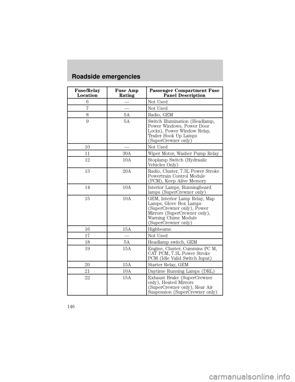
Fuse/Relay
LocationFuse Amp
RatingPassenger Compartment Fuse
Panel Description
6 Ð Not Used
7 Ð Not Used
8 5A Radio, GEM
9 5A Switch Illumination (Headlamp,
Power Windows, Power Door
Locks), Power Window Relay,
Trailer Hook Up Lamps
(SuperCrewzer only)
10 Ð Not Used
11 30A Wiper Motor, Washer Pump Relay
12 10A Stoplamp Switch (Hydraulic
Vehicles Only)
13 20A Radio, Cluster, 7.3L Power Stroke
Powertrain Control Module
(PCM), Keep Alive Memory
14 10A Interior Lamps, Runningboard
lamps (SuperCrewzer only)
15 10A GEM, Interior Lamp Relay, Map
Lamps, Glove Box Lamps
(SuperCrewzer only), Power
Mirrors (SuperCrewzer only),
Warning Chime Module
(SuperCrewzer only)
16 15A Highbeams
17 Ð Not Used
18 5A Headlamp switch, GEM
19 15A Engine, Cluster, Cummins PC M,
CAT PCM, 7.3L Power Stroke
PCM (Idle Valid Switch Input)
20 15A Starter Relay, GEM
21 10A Daytime Running Lamps (DRL)
22 15A Exhaust Brake (SuperCrewzer
only), Heated Mirrors
(SuperCrewzer only), Rear Air
Suspension (SuperCrewzer only)
Roadside emergencies
146
Page 149 of 240
Fuse/Relay
LocationFuse Amp
RatingPower Distribution Box
Description
5 15A* Air Intake Heater Relay (CAT),
Cummins PCM
6 20A* CAT PCM, Cummins PCM
7 15A* Stop Lamps
8 25A* C AT Fuel Heater
9 30A* Trailer Hook Up lamps
(SuperCrewzer only)
10 15A* Shift Modulator (Allison AT trans
only)
11 20A* Allison MD Trans, Allison
2000/2400 Trans
12 10A* Keyless Entry Module
(SuperCrewzer only)
13 10A* Park Brake Adjustment Module
(SuperCrewzer only)
14 Ð Not Used
15 7.5A* Body Builder Prep (Hydraulic
Vehicles Only)
16 10A* Allison 2000/2400 Trans
17 5A* Radio (SuperCrewzer only)
18 Ð Not Used
19 Ð Not Used
20 Ð Not Used
21 10A* GEM (Hydraulic Vehicles Only)
22 Ð Not Used
23 Ð Not Used
24 Ð Not Used
101 40A** ABS (Air Only)
102 20A** Body Builder Prep Run Feed
103 50A** Ignition Switch (JB fuses 8, 9, 11,
19, 20, 22, 23, 24, 25, 29, 30, 31)
Roadside emergencies
149
Page 150 of 240
Fuse/Relay
LocationFuse Amp
RatingPower Distribution Box
Description
104 20A** Power Point
105 20A** Power Door Locks
106 30A** Headlamps
107 50A** Junction Box Battery Feed (fuses
1, 2, 3, 4, 12, 13, 14, 15)
108 40A** Cummins Fuel Heater
109 40A** Power Windows
110 30A** Power Seats (SuperCrewzer only)
111 30A** Body Builder Prep
112 40A** Blower Motor
113 30A** Heated Seats (SuperCrewzer
only)
114 30A** E-Brake (SuperCrewzer only)
115 40A** Ignition Switch (JB fuses 5, 8, 9,
11, 21)
116 30A** Body Builder Prep
117 20A** 7.3L Power Stroke PCM
118 30A** IDM (7.3L Power Stroke only)
119
12060A** Hydraulic ABS, Air Brake Trailer
Tow Fuse Block
121
12260A** Hydromax Motor, Air Brake
Trailer Tow Fuse Block
201 Ð Washer Pump Relay
202 Ð Wiper Speed Relay
203 Ð Wiper Run/Park Relay
204 Ð 7.3L Power Stroke Neutral Start
Relay, Stoplamp Relay (CAT and
Cummins only)
205 Ð Right Hand Stop/Turn Relay
206 Ð Left Hand Stop/Turn Relay
Roadside emergencies
150
Page 152 of 240
Relays
The relay box is located on the rear crossmember near the rear bumper.
Air Brake Trailer Tow Relays (if equipped)
The relays are coded as follows:
Fuse/Relay
LocationFuse Amp
RatingDescription
1 30A** Trailer Tow Run Feed
2 30A** Trailer Tow Park/Marker Lamps
3 30A** Trailer Tow Stop Lamps
4 30A** Trailer Tow Turn/Stop Lamps
5 Ð Not Used
R1 Ð Trailer Tow Run Relay
R2 Ð Trailer Tow Stop Lamp relay
R3 Ð Trailer Tow Park/Marker Lamp Relay
R4 Ð Trailer Tow Park/Marker Lamp Relay
R5 Ð Not Used
R6 Ð Not Used
R7 Ð Trailer Tow Left Turn/Stop Lamp Relay
R8 Ð Trailer Tow Right Turn/Stop Lamp Relay
** Maxi Fuse
TRLR
RUN
RELAYNOT
USED 30A
40A
30A
30A
NOT USED LH
TURNRH
TURN NOT
USED TRLR
MARKER LP
RELAY
TRLR
STOP LP
RELAYTRLR
TAIL LAMP
RELAY1 R1 R3
R5 R6
R2 R4
R7 R82
3
4
5
Roadside emergencies
152
Page 153 of 240
SuperCrewzer (if equipped)
The relays are coded as follows:
Fuse/Relay
LocationFuse Amp
RatingDescription
1 Ð Not Used
2 Ð Not Used
3 Ð Not Used
4 Ð Not Used
5 Ð Not Used
R1 Ð Trailer Hookup Lamps Relay
R2 Ð Exhaust Brake Relay
R3 Ð Exhaust Brake Relay
R4 Ð Not Used
R5 Ð Not Used
R6 Ð Not Used
R7 Ð Not Used
R8 Ð Not Used
HOOK
LAMP
RELAYNOT
USED N.U.
N.U.
N.U.
N.U.
N.U. NOT
USED
NOT
USED NOT
USED N.U.EXHAUST
BRAKE
RELAY#2 EXHAUST
BRAKE
RELAY#11 R1 R3
R5 R6
R2 R4
R7 R82
3
4
5
Roadside emergencies
153
Page 154 of 240

JUMP STARTING YOUR VEHICLE
The gases around the battery can explode if exposed to flames,
sparks, or lit cigarettes. An explosion could result in injury or
vehicle damage.
Do not push start your vehicle. You could damage the catalytic
converter.
Batteries contain sulfuric acid which burns skin, eyes, and
clothing.
Preparing your vehicle
Also see the label on the battery.
1. Use only a 12±volt supply to start your vehicle. If you connect your
battery to a 24±volt power supply you can damage your starter, ignition
system and other electrical components. Do not attach the jumper cables
to the glow plug relay as this could severely damage the glow plugs,
injector driver module and PCM.
2. Do not disconnect the battery of the disabled vehicle as this could
damage the vehicle's electrical system.
3. Park the booster vehicle close to the disabled vehicle making sure
theydo nottouch. Set the parking brake on both vehicles and stay clear
of the engine cooling fan and other moving parts.
4. Check all battery terminals and remove any excessive corrosion before
you attach the battery cables.
5. Turn the heater fan on in both vehicles to protect any electrical
surges. Turn all other accessories off.
Roadside emergencies
154