Page 103 of 240
4. Do not depress the accelerator during starting the engine.
5. Start the engine.
If the engine does not start after 30 seconds of cranking, allow two
minutes for the starter to cool before trying again. Excessive cranking
may damage the starter.
After the engine starts:
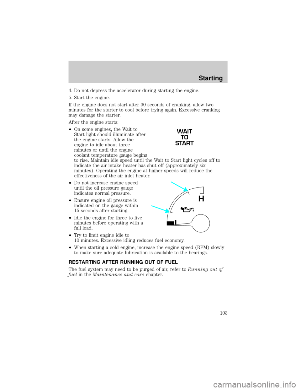
²On some engines, the Wait to
Start light should illuminate after
the engine starts. Allow the
engine to idle about three
minutes or until the engine
coolant temperature gauge begins
to rise. Maintain idle speed until the Wait to Start light cycles off to
indicate the air intake heater has shut off (approximately six
minutes). Operating the engine at higher speeds will reduce the
effectiveness of the air inlet heater.
²Do not increase engine speed
until the oil pressure gauge
indicates normal pressure.
²Ensure engine oil pressure is
indicated on the gauge within
15 seconds after starting.
²Idle the engine for three to five
minutes before operating with a
full load.
²Try to limit engine idle to
10 minutes. Excessive idling reduces fuel economy.
²When starting a cold engine, increase the engine speed (RPM) slowly
to make sure adequate lubrication is available to the bearings.
RESTARTING AFTER RUNNING OUT OF FUEL
The fuel system may need to be purged of air, refer toRunning out of
fuelin theMaintenance and carechapter.
WAIT
TO
START
L
H
Starting
103
Page 104 of 240
OPERATING THE ENGINE
Do not operate the engine at full throttle below peak torque engine
speed (RPM) for more than one minute at a time (peak torque RPM
varies from 1200-1500 RPM depending on engine rated speed).
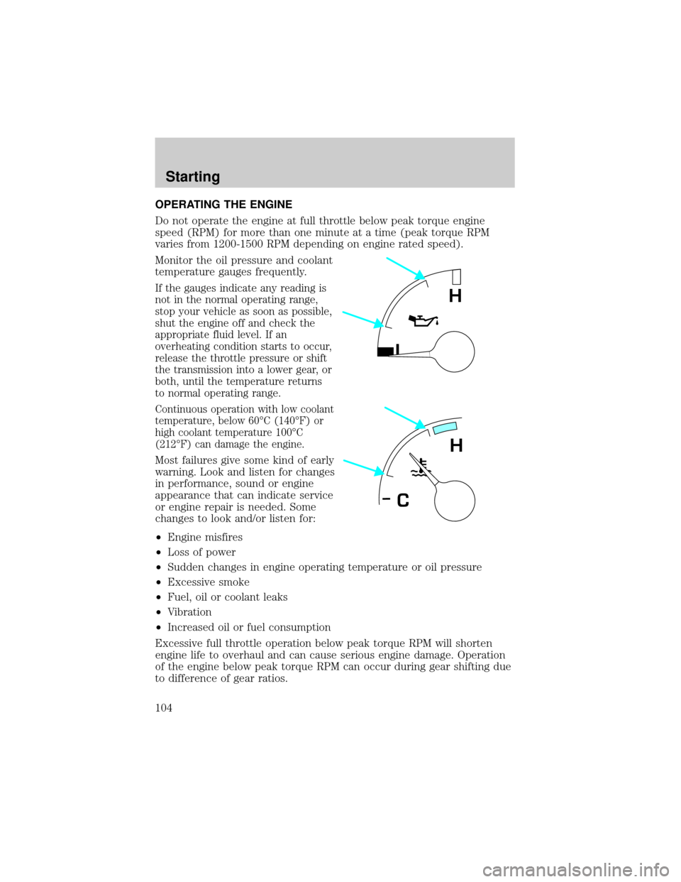
Monitor the oil pressure and coolant
temperature gauges frequently.
If the gauges indicate any reading is
not in the normal operating range,
stop your vehicle as soon as possible,
shut the engine off and check the
appropriate fluid level. If an
overheating condition starts to occur,
release the throttle pressure or shift
the transmission into a lower gear, or
both, until the temperature returns
to normal operating range.
Continuous operation with low coolant
temperature, below 60ÉC (140ÉF) or
high coolant temperature 100ÉC
(212ÉF) can damage the engine.
Most failures give some kind of early
warning. Look and listen for changes
in performance, sound or engine
appearance that can indicate service
or engine repair is needed. Some
changes to look and/or listen for:
²Engine misfires
²Loss of power
²Sudden changes in engine operating temperature or oil pressure
²Excessive smoke
²Fuel, oil or coolant leaks
²Vibration
²Increased oil or fuel consumption
Excessive full throttle operation below peak torque RPM will shorten
engine life to overhaul and can cause serious engine damage. Operation
of the engine below peak torque RPM can occur during gear shifting due
to difference of gear ratios.
L
H
H
C
Starting
104
Page 111 of 240
The parking brake is not recommended to stop a moving vehicle.
However, if the normal brakes fail, the parking brake can be used to stop
your vehicle in an emergency. Since the parking brake only applies
retardation to the rear wheels, the vehicle's stopping distance will
increase greatly and the handling of your vehicle will be adversely
affected.
Push the palm release lever on the
parking brake handle and push
down as far as possible to release
the brake. Driving with the parking
brake on will cause the brakes to
wear out quickly and reduce fuel
economy.
Parking brake Ð F650 SuperCrewzer only
Pull the yellow parking brake knob
out to apply the parking brake. Push
the knob in to release the parking
brake.
PARKING
BRAKE
PULL TO
RELEASE
APPLY
PUSH TO
Driving
111
Page 133 of 240
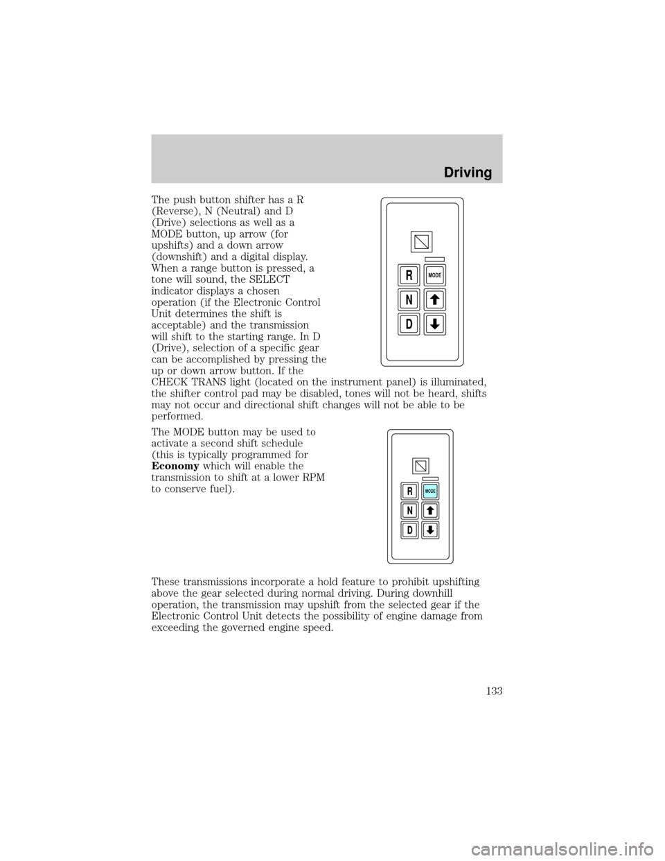
The push button shifter has a R
(Reverse), N (Neutral) and D
(Drive) selections as well as a
MODE button, up arrow (for
upshifts) and a down arrow
(downshift) and a digital display.
When a range button is pressed, a
tone will sound, the SELECT
indicator displays a chosen
operation (if the Electronic Control
Unit determines the shift is
acceptable) and the transmission
will shift to the starting range. In D
(Drive), selection of a specific gear
can be accomplished by pressing the
up or down arrow button. If the
CHECK TRANS light (located on the instrument panel) is illuminated,
the shifter control pad may be disabled, tones will not be heard, shifts
may not occur and directional shift changes will not be able to be
performed.
The MODE button may be used to
activate a second shift schedule
(this is typically programmed for
Economywhich will enable the
transmission to shift at a lower RPM
to conserve fuel).
These transmissions incorporate a hold feature to prohibit upshifting
above the gear selected during normal driving. During downhill
operation, the transmission may upshift from the selected gear if the
Electronic Control Unit detects the possibility of engine damage from
exceeding the governed engine speed.
D N R
MODE
D N R
MODE
Driving
133
Page 135 of 240
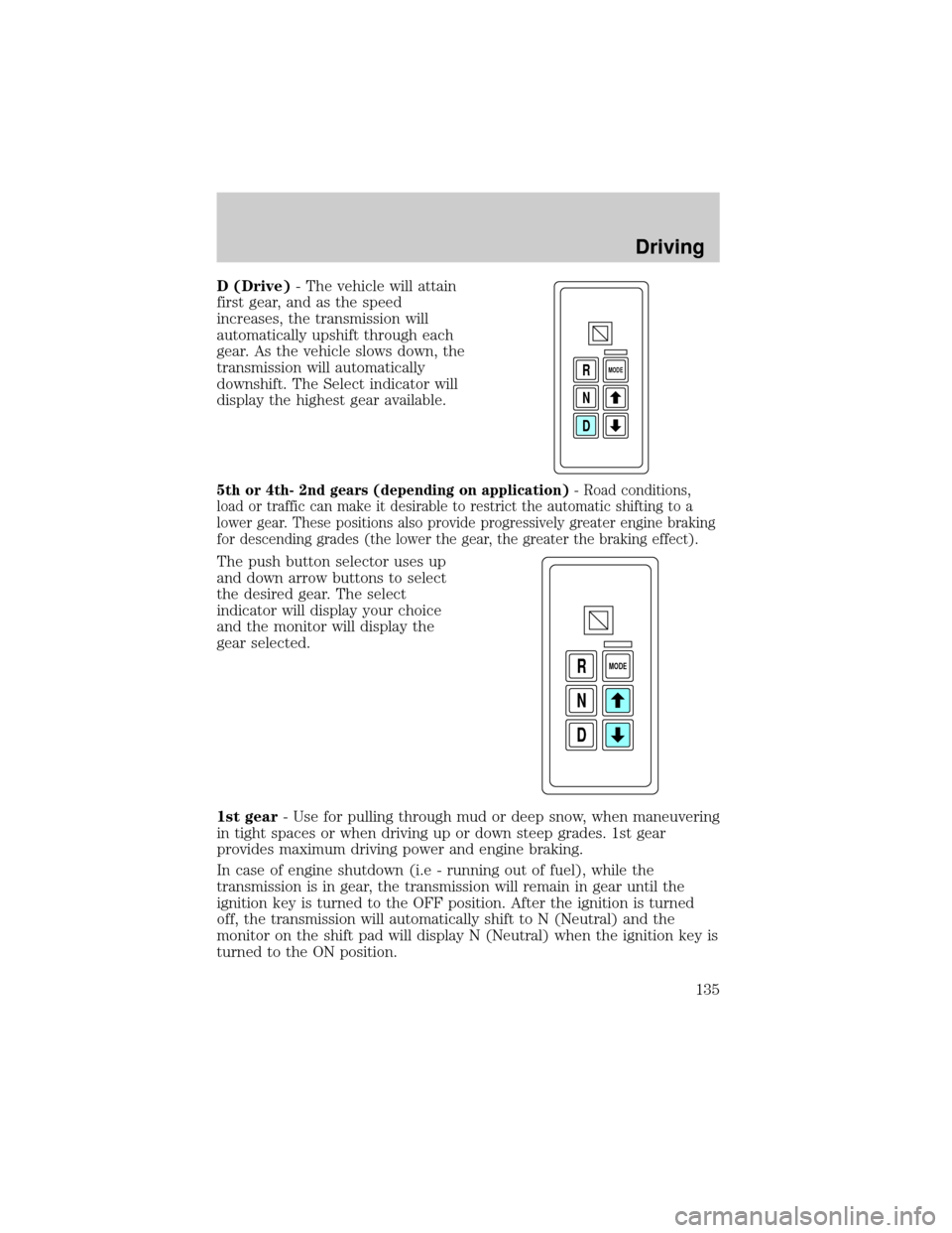
D (Drive)- The vehicle will attain
first gear, and as the speed
increases, the transmission will
automatically upshift through each
gear. As the vehicle slows down, the
transmission will automatically
downshift. The Select indicator will
display the highest gear available.
5th or 4th- 2nd gears (depending on application)- Road conditions,
load or traffic can make it desirable to restrict the automatic shifting to a
lower gear. These positions also provide progressively greater engine braking
for descending grades (the lower the gear, the greater the braking effect).
The push button selector uses up
and down arrow buttons to select
the desired gear. The select
indicator will display your choice
and the monitor will display the
gear selected.
1st gear- Use for pulling through mud or deep snow, when maneuvering
in tight spaces or when driving up or down steep grades. 1st gear
provides maximum driving power and engine braking.
In case of engine shutdown (i.e - running out of fuel), while the
transmission is in gear, the transmission will remain in gear until the
ignition key is turned to the OFF position. After the ignition is turned
off, the transmission will automatically shift to N (Neutral) and the
monitor on the shift pad will display N (Neutral) when the ignition key is
turned to the ON position.
D N R
MODE
D N R
MODE
Driving
135
Page 141 of 240
Driving through deep water where the transmission vent tube is
submerged may allow water into the transmission and cause
internal transmission damage.
FUEL CONSUMPTION IMPROVEMENT MEASURES
There are two important factors you can control to improve fuel
economy: the mechanical condition of your vehicle and how you drive it.
A properly maintained vehicle will deliver better performance than a
neglected vehicle. Always follow your maintenance schedule to keep your
vehicle in top operating condition.
Also, your driving habits have a significant influence on use of fuel. By
following these suggestions, you can stretch your fuel use:
²Avoid changes in speed as much as possible.
²Anticipate changing traffic conditions. Sudden stops and fast
acceleration waste fuel.
²Avoid extensive idling.
²Do not drive with your foot resting on the brake pedal.
WINTER FRONTS
If using an aftermarket winter front (not recommended), it must have a
permanent opening directly in line with the center of the fan drive. The
minimum opening size must be at least 774 square cm (120 square inches).
The use of an aftermarket winter front or other air flow restriction
device mounted in front of the radiator is not recommended on vehicles
equipped with chassis mounted air-to-air aftercooling. Air flow restriction
will cause high exhaust temperatures, power loss, excessive fan usage
and a reduction in fuel economy.
Driving
141
Page 147 of 240
Fuse/Relay
LocationFuse Amp
RatingPassenger Compartment Fuse
Panel Description
23 10A Electronic Flasher
24 15A Vacuum Pump, Air Dryer, ABS,
Fuel Heater Relay
25 10A Blower Motor Relay
26 10A Right Low Beam Headlamp
27 Ð Not Used
28 10A Left Low Beam Headlamp
29 10A Cluster, GEM, 7.3L Power Stroke
PCM (clutch switch input), APCM
(7.3L Power Stroke only),
Overhead Console (SuperCrewzer
only), Keyless Entry Module
(SuperCrewzer only), Traxx
(Fuel) Module (SuperCrewzer
only)
30 30A 7.3L Power Stroke PCM Diode,
7.3L Power Stroke Fuel Heater
31 15A Allison MD Transmission, Neutral
Start Relay and PCM (7.3L Power
Stroke only)
Relay 1 Ð Interior Lamps
Relay 2 Ð Not Used
Relay 3 Ð Horn
Relay 4 Ð One Touch Down
Relay 5 Ð Not Used
Roadside emergencies
147
Page 149 of 240
Fuse/Relay
LocationFuse Amp
RatingPower Distribution Box
Description
5 15A* Air Intake Heater Relay (CAT),
Cummins PCM
6 20A* CAT PCM, Cummins PCM
7 15A* Stop Lamps
8 25A* C AT Fuel Heater
9 30A* Trailer Hook Up lamps
(SuperCrewzer only)
10 15A* Shift Modulator (Allison AT trans
only)
11 20A* Allison MD Trans, Allison
2000/2400 Trans
12 10A* Keyless Entry Module
(SuperCrewzer only)
13 10A* Park Brake Adjustment Module
(SuperCrewzer only)
14 Ð Not Used
15 7.5A* Body Builder Prep (Hydraulic
Vehicles Only)
16 10A* Allison 2000/2400 Trans
17 5A* Radio (SuperCrewzer only)
18 Ð Not Used
19 Ð Not Used
20 Ð Not Used
21 10A* GEM (Hydraulic Vehicles Only)
22 Ð Not Used
23 Ð Not Used
24 Ð Not Used
101 40A** ABS (Air Only)
102 20A** Body Builder Prep Run Feed
103 50A** Ignition Switch (JB fuses 8, 9, 11,
19, 20, 22, 23, 24, 25, 29, 30, 31)
Roadside emergencies
149