Page 119 of 240
Do not use the trailer brake manual control lever for parking.
Trailer air supply control (MV-3) (Tractor package)
The MV-3 control module is a two-button, push-pull control valve housed
in a single body which includes a dual circuit supply valve and a check
valve.
Operation
During initial charge, with the system completely discharged, both
buttons are out.
When system pressure reaches
448 kPa (65 psi), the red control
(trailer supply) may be pushed in
and should stay in, charging the
trailer system and releasing the
trailer brakes.
The yellow control (parking brake)
may now be pushed in, which will
supply air to the tractor spring
brakes, releasing them.
Normal operating position
With both controls pushed in, air is supplied to the trailer and to the
tractor spring brakes; all brakes are released.
TRAILER
AIR SUPPLY
NOT FOR PARKING
PULL
TO
TOEVACUATE
PUSH
SUPPLY
PARKING
BRAKE
PULL
TOAPPLY
PUSH
TORELEASE
Driving
119
Page 120 of 240

Actuation of trailer parking or emergency brakes
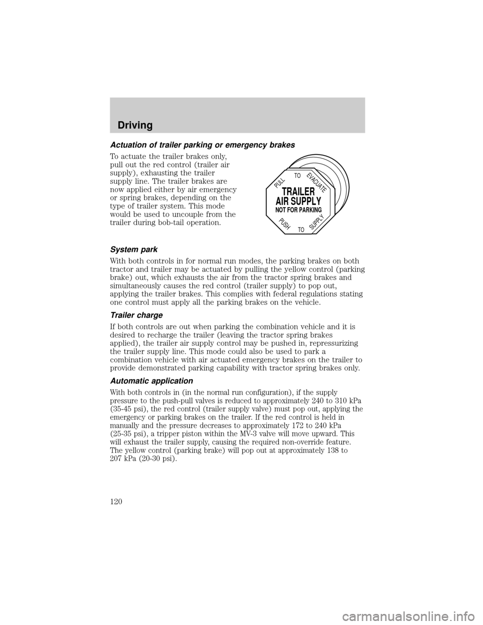
To actuate the trailer brakes only,
pull out the red control (trailer air
supply), exhausting the trailer
supply line. The trailer brakes are
now applied either by air emergency
or spring brakes, depending on the
type of trailer system. This mode
would be used to uncouple from the
trailer during bob-tail operation.
System park
With both controls in for normal run modes, the parking brakes on both
tractor and trailer may be actuated by pulling the yellow control (parking
brake) out, which exhausts the air from the tractor spring brakes and
simultaneously causes the red control (trailer supply) to pop out,
applying the trailer brakes. This complies with federal regulations stating
one control must apply all the parking brakes on the vehicle.
Trailer charge
If both controls are out when parking the combination vehicle and it is
desired to recharge the trailer (leaving the tractor spring brakes
applied), the trailer air supply control may be pushed in, repressurizing
the trailer supply line. This mode could also be used to park a
combination vehicle with air actuated emergency brakes on the trailer to
provide demonstrated parking capability with tractor spring brakes only.
Automatic application
With both controls in (in the normal run configuration), if the supply
pressure to the push-pull valves is reduced to approximately 240 to 310 kPa
(35-45 psi), the red control (trailer supply valve) must pop out, applying the
emergency or parking brakes on the trailer. If the red control is held in
manually and the pressure decreases to approximately 172 to 240 kPa
(25-35 psi), a tripper piston within the MV-3 valve will move upward. This
will exhaust the trailer supply, causing the required non-override feature.
The yellow control (parking brake) will pop out at approximately 138 to
207 kPa (20-30 psi).
TRAILER
AIR SUPPLY
NOT FOR PARKING
PULL
TO
TOEVACUATE
PUSH
SUPPLY
Driving
120
Page 126 of 240

AIR SUSPENSION DUMP VALVE
The dump valve switch activates the
dump valve. The dump valve
releases air from the air springs and
lowers the rear suspension, allowing
you to back under a low trailer
when necessary.
DRIVING WITH A MANUAL TRANSMISSION, IF EQUIPPED
Continued use of a damaged or worn clutch, prolonged clutch
slippage or downshifting at excessive speeds can result in a
failure of the engine, transmission or clutch components.
To avoid premature clutch wear and failure, do not drive with
your foot resting on the clutch pedal or use it to hold the vehicle
at a standstill on an upgrade as when waiting for a traffic light.
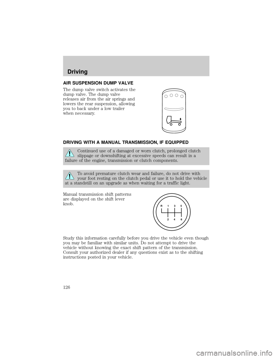
Manual transmission shift patterns
are displayed on the shift lever
knob.
Study this information carefully before you drive the vehicle even though
you may be familiar with similar units. Do not attempt to drive the
vehicle without knowing the exact shift pattern of the transmission.
Consult your authorized dealer if any questions exist as to the shifting
instructions posted in your vehicle.
R 1 3 5
4
6 2
Driving
126
Page 146 of 240

Fuse/Relay
LocationFuse Amp
RatingPassenger Compartment Fuse
Panel Description
6 Ð Not Used
7 Ð Not Used
8 5A Radio, GEM
9 5A Switch Illumination (Headlamp,
Power Windows, Power Door
Locks), Power Window Relay,
Trailer Hook Up Lamps
(SuperCrewzer only)
10 Ð Not Used
11 30A Wiper Motor, Washer Pump Relay
12 10A Stoplamp Switch (Hydraulic
Vehicles Only)
13 20A Radio, Cluster, 7.3L Power Stroke
Powertrain Control Module
(PCM), Keep Alive Memory
14 10A Interior Lamps, Runningboard
lamps (SuperCrewzer only)
15 10A GEM, Interior Lamp Relay, Map
Lamps, Glove Box Lamps
(SuperCrewzer only), Power
Mirrors (SuperCrewzer only),
Warning Chime Module
(SuperCrewzer only)
16 15A Highbeams
17 Ð Not Used
18 5A Headlamp switch, GEM
19 15A Engine, Cluster, Cummins PC M,
CAT PCM, 7.3L Power Stroke
PCM (Idle Valid Switch Input)
20 15A Starter Relay, GEM
21 10A Daytime Running Lamps (DRL)
22 15A Exhaust Brake (SuperCrewzer
only), Heated Mirrors
(SuperCrewzer only), Rear Air
Suspension (SuperCrewzer only)
Roadside emergencies
146
Page 149 of 240
Fuse/Relay
LocationFuse Amp
RatingPower Distribution Box
Description
5 15A* Air Intake Heater Relay (CAT),
Cummins PCM
6 20A* CAT PCM, Cummins PCM
7 15A* Stop Lamps
8 25A* C AT Fuel Heater
9 30A* Trailer Hook Up lamps
(SuperCrewzer only)
10 15A* Shift Modulator (Allison AT trans
only)
11 20A* Allison MD Trans, Allison
2000/2400 Trans
12 10A* Keyless Entry Module
(SuperCrewzer only)
13 10A* Park Brake Adjustment Module
(SuperCrewzer only)
14 Ð Not Used
15 7.5A* Body Builder Prep (Hydraulic
Vehicles Only)
16 10A* Allison 2000/2400 Trans
17 5A* Radio (SuperCrewzer only)
18 Ð Not Used
19 Ð Not Used
20 Ð Not Used
21 10A* GEM (Hydraulic Vehicles Only)
22 Ð Not Used
23 Ð Not Used
24 Ð Not Used
101 40A** ABS (Air Only)
102 20A** Body Builder Prep Run Feed
103 50A** Ignition Switch (JB fuses 8, 9, 11,
19, 20, 22, 23, 24, 25, 29, 30, 31)
Roadside emergencies
149
Page 150 of 240
Fuse/Relay
LocationFuse Amp
RatingPower Distribution Box
Description
104 20A** Power Point
105 20A** Power Door Locks
106 30A** Headlamps
107 50A** Junction Box Battery Feed (fuses
1, 2, 3, 4, 12, 13, 14, 15)
108 40A** Cummins Fuel Heater
109 40A** Power Windows
110 30A** Power Seats (SuperCrewzer only)
111 30A** Body Builder Prep
112 40A** Blower Motor
113 30A** Heated Seats (SuperCrewzer
only)
114 30A** E-Brake (SuperCrewzer only)
115 40A** Ignition Switch (JB fuses 5, 8, 9,
11, 21)
116 30A** Body Builder Prep
117 20A** 7.3L Power Stroke PCM
118 30A** IDM (7.3L Power Stroke only)
119
12060A** Hydraulic ABS, Air Brake Trailer
Tow Fuse Block
121
12260A** Hydromax Motor, Air Brake
Trailer Tow Fuse Block
201 Ð Washer Pump Relay
202 Ð Wiper Speed Relay
203 Ð Wiper Run/Park Relay
204 Ð 7.3L Power Stroke Neutral Start
Relay, Stoplamp Relay (CAT and
Cummins only)
205 Ð Right Hand Stop/Turn Relay
206 Ð Left Hand Stop/Turn Relay
Roadside emergencies
150
Page 152 of 240
Relays
The relay box is located on the rear crossmember near the rear bumper.
Air Brake Trailer Tow Relays (if equipped)
The relays are coded as follows:
Fuse/Relay
LocationFuse Amp
RatingDescription
1 30A** Trailer Tow Run Feed
2 30A** Trailer Tow Park/Marker Lamps
3 30A** Trailer Tow Stop Lamps
4 30A** Trailer Tow Turn/Stop Lamps
5 Ð Not Used
R1 Ð Trailer Tow Run Relay
R2 Ð Trailer Tow Stop Lamp relay
R3 Ð Trailer Tow Park/Marker Lamp Relay
R4 Ð Trailer Tow Park/Marker Lamp Relay
R5 Ð Not Used
R6 Ð Not Used
R7 Ð Trailer Tow Left Turn/Stop Lamp Relay
R8 Ð Trailer Tow Right Turn/Stop Lamp Relay
** Maxi Fuse
TRLR
RUN
RELAYNOT
USED 30A
40A
30A
30A
NOT USED LH
TURNRH
TURN NOT
USED TRLR
MARKER LP
RELAY
TRLR
STOP LP
RELAYTRLR
TAIL LAMP
RELAY1 R1 R3
R5 R6
R2 R4
R7 R82
3
4
5
Roadside emergencies
152
Page 153 of 240
SuperCrewzer (if equipped)
The relays are coded as follows:
Fuse/Relay
LocationFuse Amp
RatingDescription
1 Ð Not Used
2 Ð Not Used
3 Ð Not Used
4 Ð Not Used
5 Ð Not Used
R1 Ð Trailer Hookup Lamps Relay
R2 Ð Exhaust Brake Relay
R3 Ð Exhaust Brake Relay
R4 Ð Not Used
R5 Ð Not Used
R6 Ð Not Used
R7 Ð Not Used
R8 Ð Not Used
HOOK
LAMP
RELAYNOT
USED N.U.
N.U.
N.U.
N.U.
N.U. NOT
USED
NOT
USED NOT
USED N.U.EXHAUST
BRAKE
RELAY#2 EXHAUST
BRAKE
RELAY#11 R1 R3
R5 R6
R2 R4
R7 R82
3
4
5
Roadside emergencies
153