Page 107 of 240

Although OSHA or other governmental regulations may require use of an
electrical or mechanical back-up alarm to warn bystanders, such an
alarm does not assure that the intended path is clear.
An electrical back-up alarm, if installed, is connected to the back-up
lamp circuit.
HYDRAULIC BRAKES (IF EQUIPPED)
Your service brakes are self-adjusting. Refer to the Scheduled
maintenance guide for scheduled maintenance.
Occasional brake noise is normal and often does not indicate a
performance concern with the vehicle's brake system. In normal
operation, automotive brake systems may emit occasional or intermittent
squeal or groan noises when the brakes are applied. Such noises are
usually heard during the first few brake applications in the morning;
however, they may be heard at any time while braking and can be
aggravated by environmental conditions such as cold, heat, moisture,
road dust, salt or mud. If a ªmetal-to-metal,º ªcontinuous grindingº or
ªcontinuous squealº sound is present while braking, the brake linings
may be worn-out and should be inspected by a qualified service
technician.
If you are driving down a long or steep hill, shift to a lower gear.
Do not apply your brakes continuously, as they may overheat
and become less effective.
Four-wheel anti-lock brake system (ABS) (if equipped)
On vehicles equipped with an anti-lock braking system (ABS), a noise
from the hydraulic pump motor and pulsation in the pedal may be
observed during ABS braking events. Pedal pulsation coupled with noise
while braking under panic conditions or on loose gravel, bumps, wet or
snowy roads is normal and indicates proper functioning of the vehicle's
anti-lock brake system. If the vehicle has continuous vibration or shudder
in the steering wheel while braking, the vehicle should be inspected by a
qualified service technician.
Driving
107
Page 115 of 240
![FORD F650 2001 10.G Owners Manual When air pressure is insufficient
(below 534 kPa [60 psi]), a warning
light illuminates and a buzzer
sounds when the ignition is in the
ON position.
This condition may be caused by excessive brake app FORD F650 2001 10.G Owners Manual When air pressure is insufficient
(below 534 kPa [60 psi]), a warning
light illuminates and a buzzer
sounds when the ignition is in the
ON position.
This condition may be caused by excessive brake app](/manual-img/11/5067/w960_5067-114.png)
When air pressure is insufficient
(below 534 kPa [60 psi]), a warning
light illuminates and a buzzer
sounds when the ignition is in the
ON position.
This condition may be caused by excessive brake applications depleting
the system air pressure. If this condition occurs, stop driving the vehicle
until the compressor has fully recharged the air system. Do not move the
vehicle in this condition because the brake system may be inoperative.
Select a gear ratio to help slow your vehicle before descending grades.
Supplement with brakes as required to safely slow the vehicle and avoid
overspeeding the engine.
Air chamber stroke indication
All Ford air chamber push rods have orange stroke indicator stripes that
alert the operator when the braking system requires adjustment or
repair. The orange stripe is painted on the air chamber push rod at the
slack adjuster readjustment stroke dimension.
Air brake inspection and adjustment should be performed by a qualified
service technician in accordance with the instructions in the Ford Truck
Service Manual.
Cam brakesÐautomatic slack adjusters
Standard air brakes (cam) are
equipped with automatic brake
adjusters. Automatic adjustment
occurs during forward and reverse
brake applications. Inspect brakes
for proper adjustment at the
intervals listed in the vehicle Service
Maintenance Guide.
!
BRAKE
Driving
115
Page 141 of 240

Driving through deep water where the transmission vent tube is
submerged may allow water into the transmission and cause
internal transmission damage.
FUEL CONSUMPTION IMPROVEMENT MEASURES
There are two important factors you can control to improve fuel
economy: the mechanical condition of your vehicle and how you drive it.
A properly maintained vehicle will deliver better performance than a
neglected vehicle. Always follow your maintenance schedule to keep your
vehicle in top operating condition.
Also, your driving habits have a significant influence on use of fuel. By
following these suggestions, you can stretch your fuel use:
²Avoid changes in speed as much as possible.
²Anticipate changing traffic conditions. Sudden stops and fast
acceleration waste fuel.
²Avoid extensive idling.
²Do not drive with your foot resting on the brake pedal.
WINTER FRONTS
If using an aftermarket winter front (not recommended), it must have a
permanent opening directly in line with the center of the fan drive. The
minimum opening size must be at least 774 square cm (120 square inches).
The use of an aftermarket winter front or other air flow restriction
device mounted in front of the radiator is not recommended on vehicles
equipped with chassis mounted air-to-air aftercooling. Air flow restriction
will cause high exhaust temperatures, power loss, excessive fan usage
and a reduction in fuel economy.
Driving
141
Page 148 of 240

Power distribution box
The power distribution box is located in the engine compartment. The
power distribution box contains high-current fuses that protect your
vehicle's main electrical systems from overloads.
Always disconnect the battery before servicing high current fuses.
Always replace the cover to the Power Distribution Box before
reconnecting the battery or refilling fluid reservoirs.
If the battery has been disconnected and reconnected, refer to the
Batterysection of theMaintenance and carechapter.
The high-current fuses and relays are coded as follows.
Fuse/Relay
LocationFuse Amp
RatingPower Distribution Box
Description
1 15A* Park Lamps, Roof Lamps
2 25A* Cummins Powertrain Control
Module (PCM)
15A* Foglamps (SuperCrewzer only)
3 10A* Generator
4 15A* Washer Pump
503
304
303
302301
502
501
207201
202
203
204122118114110106102
121117113109105101
120116112108104
119115111107103
24
209206
208
18161412108642
1715131197531
205
23
22
21
401
20
19
Roadside emergencies
148
Page 158 of 240
CHECKING UNDER THE HOOD
Opening the hood
The hood and fenders are held in position by a latch located on each
fender.
The parking brake must be fully set before opening the hood or
possible personal injury may occur.
If you must leave the engine running while checking under the
hood, do not allow any loose clothing, jewelry, hair or other
items to get near moving engine components or possible personal
injury may occur.
To open the hood:
1. Set the parking brake, shift into N (Neutral) (automatic transmission)
or 1 (First) (manual transmission) and turn the engine off.
2. Lift upward on the bottom of
each latch.
3. Pull the bottom of each latch
away from the fender.
Maintenance and care
158
Page 159 of 240
4. Tilt the hood forward until
stopped by the retaining cables.
To lower the hood:
1. Push the hood rearward at the top center of the hood above the grille
until closed.
2. Engage the latch on each fender.
3. Push down on the bottom of each latch until locked.
To avoid the possibility of personal injury, never stand beneath
the hood when it is being raised or lowered.
ENGINE OIL
Checking engine oil levelÐCummins B and Caterpillar 3126 B engines
Refer to the appropriate engine operator's manual for information on the
engine oil.
Maintenance and care
159
Page 160 of 240

Checking engine oil levelÐ7.3L Power Stroke engine
Refer to the Scheduled Maintenance Guide for the appropriate intervals
for checking the engine oil.
Check the engine oil level consistently and accurately. The following
procedure is recommended:
1. Start the engine and let it run until it reaches normal operating
temperature (the engine coolant temperature gauge indicator will be
near the center of the normal area between H and C).
2. Park the vehicle on level ground.
3. Set the parking brake and shift into N (Neutral) (automatic
transmission) or 1 (First) (manual transmission).
4. Turn off the engine and wait a few minutes for the oil to drain
completely into the oil pan.
5. Open the hood. Protect yourself from engine heat.
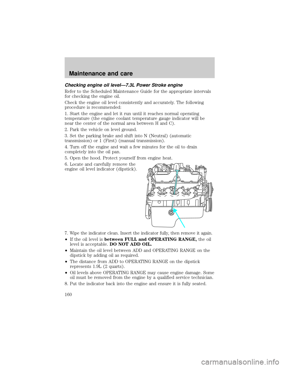
6. Locate and carefully remove the
engine oil level indicator (dipstick).
7. Wipe the indicator clean. Insert the indicator fully, then remove it again.
²If the oil level isbetween FULL and OPERATING RANGE,the oil
level is acceptable.DO NOT ADD OIL.
²Maintain the oil level between ADD and OPERATING RANGE on the
dipstick by adding oil as required.
²The distance from ADD to OPERATING RANGE on the dipstick
represents 1.9L (2 quarts).
²Oil levels above OPERATING RANGE may cause engine damage. Some
oil must be removed from the engine by a qualified service technician.
8. Put the indicator back into the engine and ensure it is fully seated.
Maintenance and care
160
Page 161 of 240

Engine oil and filter recommendationsÐCummins B and Caterpillar
3126 B engines
Refer to the appropriate engine operator's manual for information on the
engine oil.
Engine oil and filter recommendationsÐ7.3L Power Stroke engine
To help achieve proper engine performance and durability, it is important
that you:
²Use only engine lubricating oils and oil filters of the proper quality.
²Change the engine oil and filterno laterthan the recommended
service interval. Refer to the Scheduled Maintenance Guide for the
appropriate intervals for changing the engine oil and filter.
²Change your engine oil and filter more frequently if your vehicle
operation includes extended periods of idling or low-speed operation,
driving for a long time in cold temperatures or short driving distances.
Diesel engines require specially formulated oil to resist contamination.
Proper quality oils also provide maximum efficiency of the crankcase
ventilation system which reduces air pollution.
Use Motorcraft motor oil or an equivalent oil meeting Ford specification
WSS-M2C171±C or API service category designation CH-4/SJ. Do not use
oils labeled with only one of the category designations SG, SH, SJ, CE,
CF-4, CH-4 or CG-4, as they could cause engine damage.
Diesel engine oils with improved fuel economy properties (energy
conserving) are currently available. If you use an energy conserving oil,
be sure it meets Ford specification WSS-M2C171±C or API service
category designation CH-4/SJ and is of the proper viscosity grade for the
temperature range in which you expect to operate your vehicle. Some
energy conserving oils do not meet the requirements necessary for your
diesel engine.
Maintenance and care
161