2001 FORD F650 brake light
[x] Cancel search: brake lightPage 108 of 240
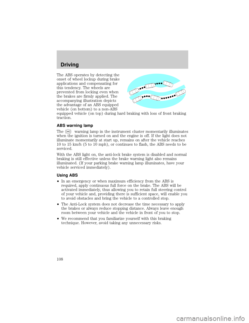
The ABS operates by detecting the
onset of wheel lockup during brake
applications and compensating for
this tendency. The wheels are
prevented from locking even when
the brakes are firmly applied. The
accompanying illustration depicts
the advantage of an ABS equipped
vehicle (on bottom) to a non-ABS
equipped vehicle (on top) during hard braking with loss of front braking
traction.
ABS warning lamp
The
ABSwarning lamp in the instrument cluster momentarily illuminates
when the ignition is turned on and the engine is off. If the light does not
illuminate momentarily at start up, remains on after the vehicle reaches
10 to 15 km/h (5 to 10 mph), or continues to flash, the ABS needs to be
serviced.
With the ABS light on, the anti-lock brake system is disabled and normal
braking is still effective unless the brake warning light also remains
illuminated. (If your parking brake warning lamp illuminates, have your
vehicle serviced immediately).
Using ABS
²In an emergency or when maximum efficiency from the ABS is
required, apply continuous full force on the brake. The ABS will be
activated immediately, thus allowing you to retain full steering control
of your vehicle and, providing there is sufficient space, will enable you
to avoid obstacles and bring the vehicle to a controlled stop.
²The Anti-Lock system does not decrease the time necessary to apply
the brakes or always reduce stopping distance. Always leave enough
room between your vehicle and the vehicle in front of you to stop.
²We recommend that you familiarize yourself with this braking
technique. However, avoid taking any unnecessary risks.
Driving
108
Page 109 of 240
Hydraulic brake booster system (Hydromax)
The Hydromax systems receive fluid pressure from the power steering
pump to provide power assist during braking.
The Hydromax booster receives backup pressure from the reserve
system electric pump whenever the fluid in the power steering system is
not flowing. When the engine is OFF, the pump will turn on if the brake
pedal is applied, or if the ignition is turned to the ON position.
The sound of the pump operating may be heard by the driver, but this is
a normal characteristic of the system.
The reserve system provides reduced braking power, so the vehicle
should be operated under these conditions with caution, and only to seek
service repair and remove the vehicle from the roadway.
For Hydromax under normal operating conditions noise of the fluid
flowing through the booster may be heard whenever the brake is applied.
This condition is normal. Vehicle service is not required.
If braking performance or pedal response becomes very poor, even when
the pedal is strongly applied, this may indicate the presence of air in the
hydraulic system or fluid leakage. Stop the vehicle safely as soon as
possible and seek service immediately.
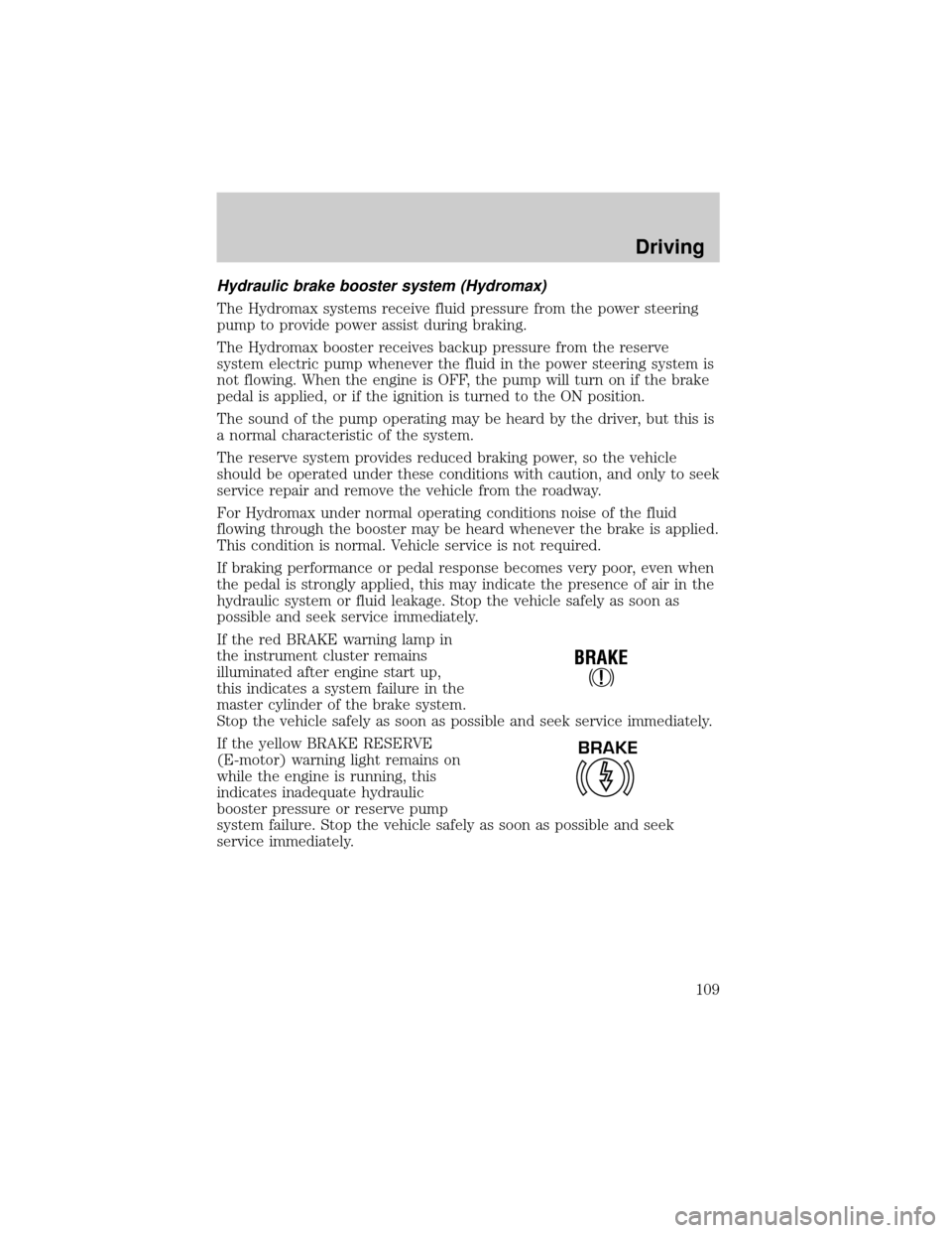
If the red BRAKE warning lamp in
the instrument cluster remains
illuminated after engine start up,
this indicates a system failure in the
master cylinder of the brake system.
Stop the vehicle safely as soon as possible and seek service immediately.
If the yellow BRAKE RESERVE
(E-motor) warning light remains on
while the engine is running, this
indicates inadequate hydraulic
booster pressure or reserve pump
system failure. Stop the vehicle safely as soon as possible and seek
service immediately.
!
BRAKE
BRAKE
Driving
109
Page 114 of 240
Occasional or intermittent brake squeal may result from environmental
conditions such as cold, hot, wet, snow, salt, mud, etc. This condition will
not affect braking effectiveness. The brakes should be checked only if
squeal occurs continuously with every application.
If brakes do not grip well
²If you have been driving through deep water, gently apply the brakes
several times while the vehicle is moving slowly.
²Let the brakes cool if you have been using them excessively, as in
mountain driving or after several fast, high speed stops.
²Check brake adjustment.
²Check brake linings for excessive wear.
²Check system air pressure.
Air brakes
After starting the engine, give the air compressor time to build up the air
pressure to 414 kPa (60 psi) before moving the vehicle.
Do not drive or continue to drive if the low air pressure buzzer
is sounding or the brake warning light is lit. These warnings
indicate that air pressure is not to normal operating level. Continued
use of the vehicle could result in loss of braking ability.
Avoid repeated light application of the brake pedal. This will
deplete air pressure faster and could result in loss of braking
capability.
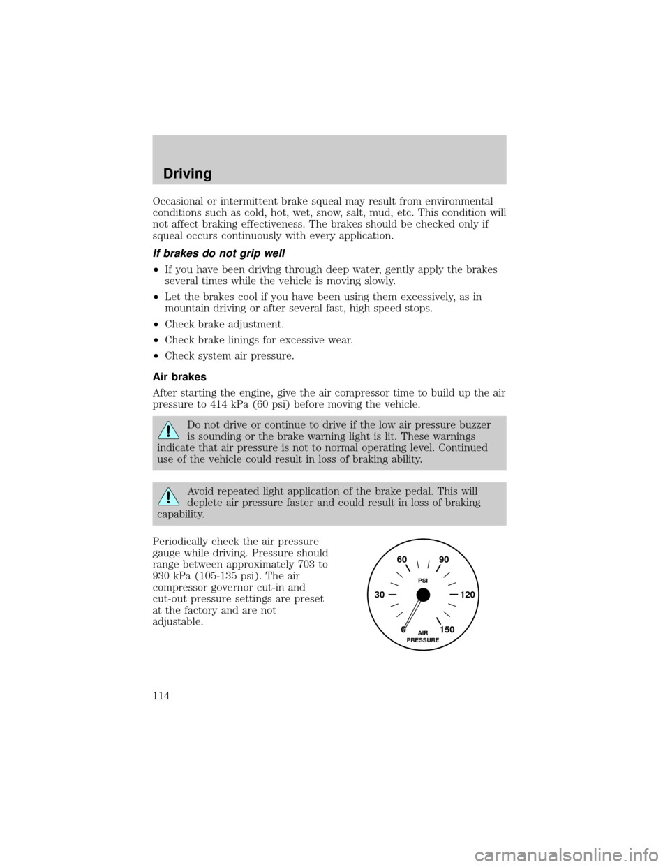
Periodically check the air pressure
gauge while driving. Pressure should
range between approximately 703 to
930 kPa (105-135 psi). The air
compressor governor cut-in and
cut-out pressure settings are preset
at the factory and are not
adjustable.
0 30 12090 60
150AIR
PRESSUREPSI
Driving
114
Page 115 of 240
![FORD F650 2001 10.G Owners Manual When air pressure is insufficient
(below 534 kPa [60 psi]), a warning
light illuminates and a buzzer
sounds when the ignition is in the
ON position.
This condition may be caused by excessive brake app FORD F650 2001 10.G Owners Manual When air pressure is insufficient
(below 534 kPa [60 psi]), a warning
light illuminates and a buzzer
sounds when the ignition is in the
ON position.
This condition may be caused by excessive brake app](/manual-img/11/5067/w960_5067-114.png)
When air pressure is insufficient
(below 534 kPa [60 psi]), a warning
light illuminates and a buzzer
sounds when the ignition is in the
ON position.
This condition may be caused by excessive brake applications depleting
the system air pressure. If this condition occurs, stop driving the vehicle
until the compressor has fully recharged the air system. Do not move the
vehicle in this condition because the brake system may be inoperative.
Select a gear ratio to help slow your vehicle before descending grades.
Supplement with brakes as required to safely slow the vehicle and avoid
overspeeding the engine.
Air chamber stroke indication
All Ford air chamber push rods have orange stroke indicator stripes that
alert the operator when the braking system requires adjustment or
repair. The orange stripe is painted on the air chamber push rod at the
slack adjuster readjustment stroke dimension.
Air brake inspection and adjustment should be performed by a qualified
service technician in accordance with the instructions in the Ford Truck
Service Manual.
Cam brakesÐautomatic slack adjusters
Standard air brakes (cam) are
equipped with automatic brake
adjusters. Automatic adjustment
occurs during forward and reverse
brake applications. Inspect brakes
for proper adjustment at the
intervals listed in the vehicle Service
Maintenance Guide.
!
BRAKE
Driving
115
Page 123 of 240
Exhaust brake operating characteristics
When you remove your feet from both the accelerator and clutch pedals
and the exhaust brake switch is in the ON position, the exhaust brake is
activated. The following conditions should exist if the brake is operating
properly:
²A slight change in the sound of the engine when the exhaust brake is
activated.
²Exhaust smoke appears normal.
²Engine temperature remains in the normal operating range.
²Road speed usually decreases when the exhaust brake is applied
during a descent, except when the vehicle is carrying a heavy load or
the grade is extremely steep. In these instances, you may need to
apply the service brakes occasionally.
²During a descent, the tachometer usually shows a drop in RPM
depending on the grade and the vehicle load.
²Do not expect a retarding effect similar to sudden hard application of
the service brakes. The exhaust brake retards the vehicle with a
smooth braking effect.
²Depending on the grade and vehicle load, you may or may not feel the
retarding force acting against your body when the brake is applied.
The brake's retarding force is actually preventing the vehicle from
going much faster.
Make sure the exhaust brake is turned off before shutting off the engine.
Installing an exhaust or auxiliary brake should never allow the
engine to exceed maximum governed speeds under any
conditions. Refer to theStartingchapter.
Air brake reservoir draining
Failure to drain air brake reservoirs can result in a reduction or
loss of braking ability due to fluid accumulation in the reservoir
and/or possible freeze-up during cold weather.
Driving
123
Page 138 of 240
Do not allow your vehicle to coast in N (Neutral). Engine
braking is not available in N (Neutral). Allowing your vehicle to
coast in N (Neutral) may result in loss of vehicle control and severe
internal transmission damage.
D (DriveÐNormal driving position)
In this position, the transmission starts in first gear and automatically
shifts through second, third, fourth and fifth depending on load and
speed demands. When the vehicle is slowing down, the transmission will
automatically downshift. This range is used for highway driving under
normal conditions.
4 and 2 (Fourth and Second)
Use this position when road, load or traffic conditions make it desirable
to restrict the automatic shifting to a lower range. These ranges provide
greater engine braking than D (Drive). When conditions no longer
require these lower gears, shift back to D (Drive).
1 (First)
The transmission has to be manually shifted into 1 (First) and will not
shift into a higher gear. Use this position when pulling through mud or
snow, driving up steep grades, hauling extra heavy loads or where
maximum reduction is required.
Power take-off (PTO) operation with an Allison automatic
transmission (except MD applications and vehicles equipped with
a Caterpillar 3126E engine)
The power take-off can be operated while the vehicle is standing or
moving.
To engage the PTO, apply the brakes and shift to any gear other than N
(Neutral) - this stops the rotation of the PTO drive gear in the
transmission - then engage the PTO.
If engagement is prevented by the gear teeth not meshing properly,
release the brakes and allow the vehicle to creep slightly - or shift the
selector to N (Neutral) and then back in gear. The PTO should never be
engaged by clashing the gear teeth. This may damage the PTO unit and
the transmission PTO drive gear teeth. This could result in further
damage to the transmission and PTO.
Driving
138
Page 140 of 240
MAXIMUM VEHICLE LOADING
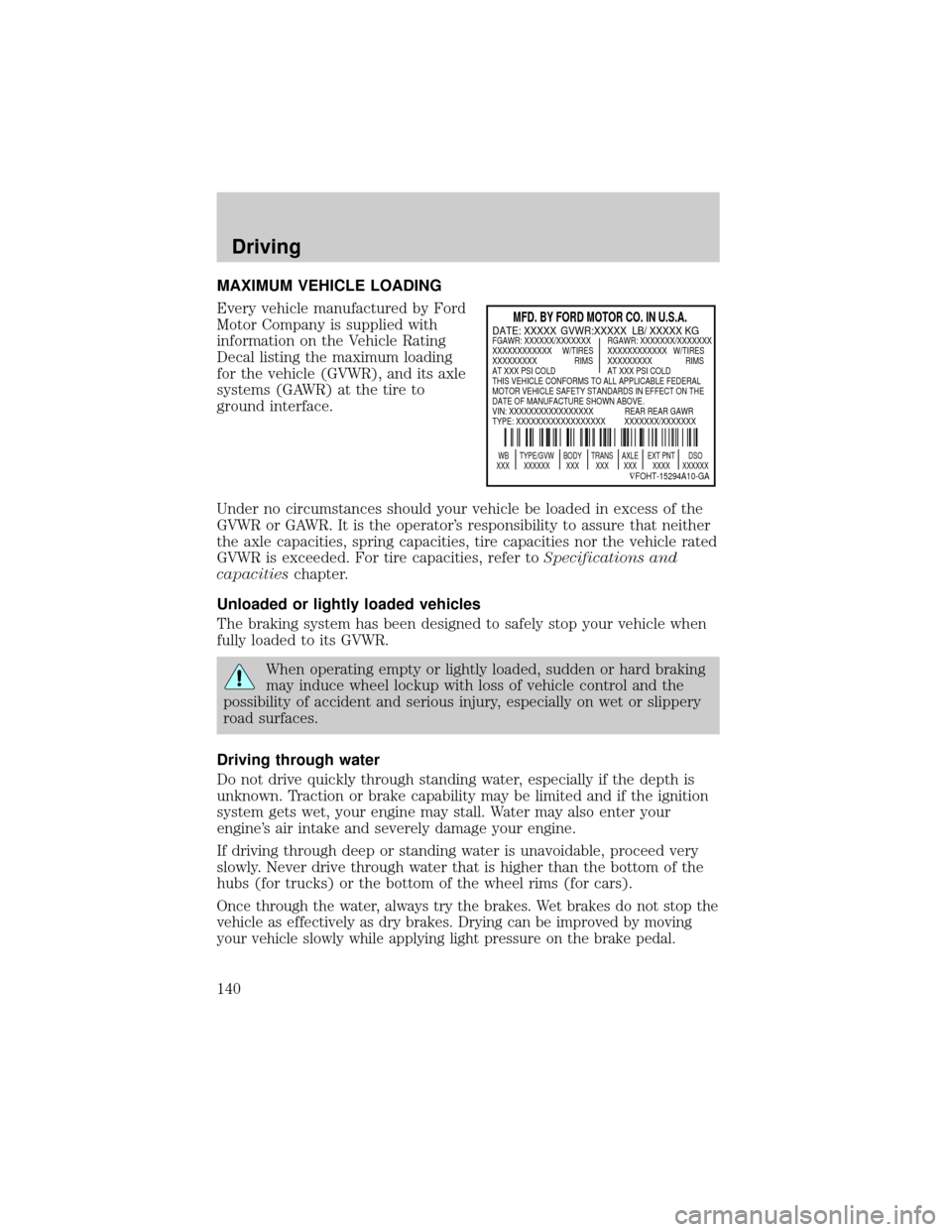
Every vehicle manufactured by Ford
Motor Company is supplied with
information on the Vehicle Rating
Decal listing the maximum loading
for the vehicle (GVWR), and its axle
systems (GAWR) at the tire to
ground interface.
Under no circumstances should your vehicle be loaded in excess of the
GVWR or GAWR. It is the operator's responsibility to assure that neither
the axle capacities, spring capacities, tire capacities nor the vehicle rated
GVWR is exceeded. For tire capacities, refer toSpecifications and
capacitieschapter.
Unloaded or lightly loaded vehicles
The braking system has been designed to safely stop your vehicle when
fully loaded to its GVWR.
When operating empty or lightly loaded, sudden or hard braking
may induce wheel lockup with loss of vehicle control and the
possibility of accident and serious injury, especially on wet or slippery
road surfaces.
Driving through water
Do not drive quickly through standing water, especially if the depth is
unknown. Traction or brake capability may be limited and if the ignition
system gets wet, your engine may stall. Water may also enter your
engine's air intake and severely damage your engine.
If driving through deep or standing water is unavoidable, proceed very
slowly. Never drive through water that is higher than the bottom of the
hubs (for trucks) or the bottom of the wheel rims (for cars).
Once through the water, always try the brakes. Wet brakes do not stop the
vehicle as effectively as dry brakes. Drying can be improved by moving
your vehicle slowly while applying light pressure on the brake pedal.
MFD. BY FORD MOTOR CO. IN U.S.A.
WB TYPE/GVW BODY TRANS AXLE EXT PNT DSO
XXX XXXXXX XXX XXX XXX XXXX XXXXXX
ÑFOHT-15294A10-GA
DATE: XXXXX GVWR:XXXXX LB/ XXXXX KGFGAWR: XXXXXX/XXXXXXX RGAWR: XXXXXXX/XXXXXXX
XXXXXXXXXXXX W/TIRES XXXXXXXXXXXX W/TIRES
XXXXXXXXX RIMS XXXXXXXXX RIMS
AT XXX PSI COLD AT XXX PSI COLD
THIS VEHICLE CONFORMS TO ALL APPLICABLE FEDERAL
MOTOR VEHICLE SAFETY STANDARDS IN EFFECT ON THE
DATE OF MANUFACTURE SHOWN ABOVE.
VIN: XXXXXXXXXXXXXXXXX REAR REAR GAWR
TYPE: XXXXXXXXXXXXXXXXXX XXXXXXX/XXXXXXX
Driving
140
Page 145 of 240

Passenger compartment fuse panel
The fuse panel is located below and to the left of the steering wheel by
the brake pedal. Remove the panel cover to access the fuses.
To remove a fuse use the fuse puller tool provided on the fuse panel cover.
The fuses are coded as follows.
Fuse/Relay
LocationFuse Amp
RatingPassenger Compartment Fuse
Panel Description
1 20A Horn
2 15A Turn/Hazard Lamps
3 20A Cigar Lighter
4 10A Diagnostic Connectors
5 15A Back-Up Lamps, DRL Relays,
Blend Door Actuator, Heated Seat
Module (SuperCrewzer only),
On/Off Fan Clutch (SuperCrewzer
only), Warning Chime Module
(SuperCrewzer only)
Relay #1
Relay #2
Relay #3
Horn
Relay #4
Relay #5 One Touch
Down Interior
Lamps#1
#12#22
#2
#3
#4
#5
#6
#7
#8
#9
#10
#11#13
#23
#14
#15
#16
#17#24
#25
#26
#27
#18
#28
#19
#29
#20
#21#30
#31
Roadside emergencies
145