Page 130 of 224
The fuel pump shut-off switch is
located in the passenger's foot well,
by the kick panel.
Use the following procedure to reset the fuel pump shut-off switch.
1. Turn the ignition to the OFF position.
2. Check the fuel system for leaks.
3. If no fuel leak is apparent, reset the fuel pump shut-off switch by
pushing in on the reset button.
4. Turn the ignition to the ON position. Pause for a few seconds and
return the key to the OFF position.
5. Make a further check for leaks in the fuel system.
FUSES AND RELAYS
Fuses
If electrical components in the
vehicle are not working, a fuse may
have blown. Blown fuses are
identified by a broken wire within
the fuse. Check the appropriate
fuses before replacing any electrical
components.
15
Roadside emergencies
130
Page 135 of 224

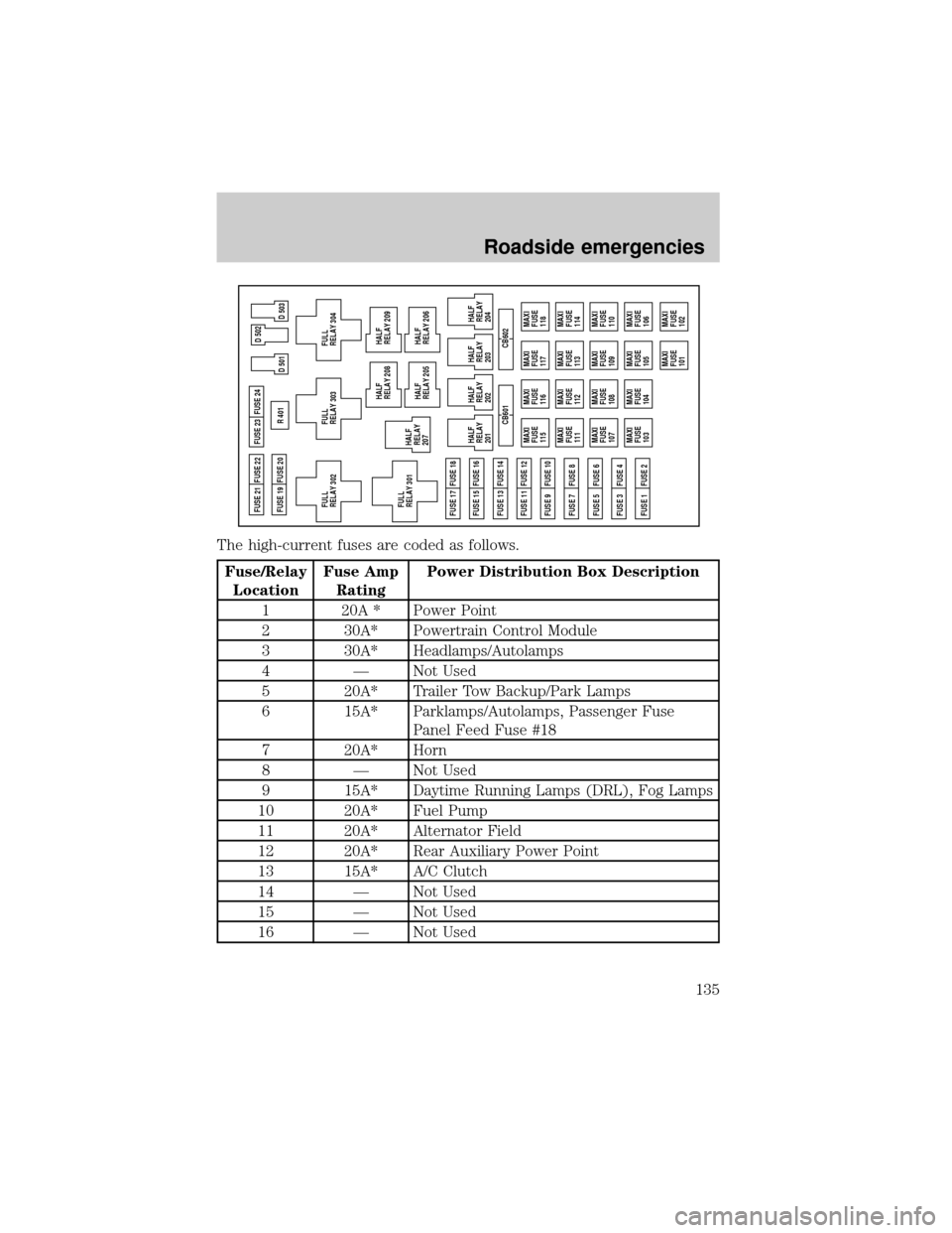
The high-current fuses are coded as follows.
Fuse/Relay
LocationFuse Amp
RatingPower Distribution Box Description
1 20A * Power Point
2 30A* Powertrain Control Module
3 30A* Headlamps/Autolamps
4 Ð Not Used
5 20A* Trailer Tow Backup/Park Lamps
6 15A* Parklamps/Autolamps, Passenger Fuse
Panel Feed Fuse #18
7 20A* Horn
8 Ð Not Used
9 15A* Daytime Running Lamps (DRL), Fog Lamps
10 20A* Fuel Pump
11 20A* Alternator Field
12 20A* Rear Auxiliary Power Point
13 15A* A/C Clutch
14 Ð Not Used
15 Ð Not Used
16 Ð Not Used
MAXI
FUSE
115MAXI
FUSE
116MAXI
FUSE
117
MAXI
FUSE
118
MAXI
FUSE
111MAXI
FUSE
112MAXI
FUSE
113
MAXI
FUSE
114
MAXI
FUSE
107MAXI
FUSE
108MAXI
FUSE
109
MAXI
FUSE
110
MAXI
FUSE
103MAXI
FUSE
104MAXI
FUSE
105
MAXI
FUSE
106
MAXI
FUSE
101MAXI
FUSE
102 CB601 CB602 FUSE 17 FUSE 18FUSE 21 FUSE 22
FUSE 19 FUSE 20FUSE 23
FULL
RELAY 302R 401
D 501 FUSE 24
FUSE 15 FUSE 16
FUSE 13 FUSE 14
FUSE 11 FUSE 12
FUSE 9 FUSE 10
FUSE 7 FUSE 8
FUSE 5 FUSE 6
FUSE 3 FUSE 4
FUSE 1 FUSE 2
D 503 D 502
FULL
RELAY 301HALF
RELAY
207
FULL
RELAY 303
FULL
RELAY 304
HALF
RELAY
201
HALF
RELAY
202HALF
RELAY 208
HALF
RELAY 209
HALF
RELAY 205
HALF
RELAY 206
HALF
RELAY
203
HALF
RELAY
204
Roadside emergencies
135
Page 136 of 224

Fuse/Relay
LocationFuse Amp
RatingPower Distribution Box Description
17 Ð Not Used
18 15A* Powertrain Control Module, Fuel Injectors,
Fuel Pump Relay, Idle Air Control, Mass Air
Flow Sensor
19 10A* Trailer Tow Stop and Right Turn Lamp
20 10A* Trailer Tow Stop and Left Turn Lamp
21 Ð Not Used
22 Ð Not Used
23 15A* HEGO Sensor, Canister Vent, Automatic
Transmission, CMS Sensor
24 Ð Not Used
101 30A** Trailer Tow Battery Charge
102 50A** Four Wheel Antilock Brake Module
103 50A** Junction Block Battery Feed
104 30A** 4x4 Shift Motor & Clutch
105 40A** Climate Control Front Blower
106 Ð Not Used
107 Ð Not Used
108 30A** Trailer Tow Electric Brake
109 Ð Not Used
110 Ð Not Used
111 40A** Ignition Switch Battery Feed (Start and
Run Circuits)
112 30A** Drivers Power Seat, Adjustable Pedals
113 40A** Ignition Switch Battery Feed (Run and
Accessory Circuits)
114 Ð Not Used
115 20A** Power Door Locks
116 Ð Not Used
117 Ð Not Used
118 Ð Not Used
201 Ð Trailer Tow Park Lamp Relay
Roadside emergencies
136
Page 137 of 224

Fuse/Relay
LocationFuse Amp
RatingPower Distribution Box Description
202 Ð Front Wiper Run/Park Relay
203 Ð Trailer Tow Backup Lamp Relay
204 Ð A/C Clutch Relay
205 Ð Horn Relay
206 Ð Fog Lamp Relay
207 Ð Front Washer Pump Relay
208 Ð Not Used
209 Ð Front Wiper Hi/Lo Relay
301 Ð Fuel Pump Relay
302 Ð Trailer Tow Battery Charge Relay
303 Ð Not Used
304 Ð Powertrain Control Module Relay
305 Ð Not Used
306 Ð Not Used
401 Ð Not Used
501 Ð Powertrain Control Module Diode
502 Ð A/C Compressor Diode
503 Ð Not Used
601 30A CB Power Windows, Moonroof
602 Ð Not Used
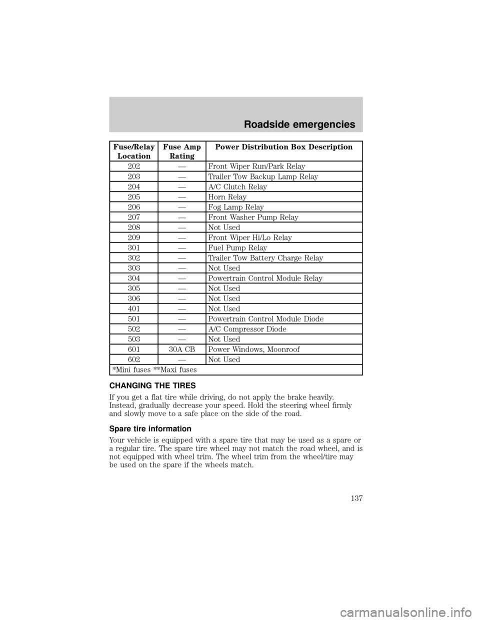
*Mini fuses **Maxi fuses
CHANGING THE TIRES
If you get a flat tire while driving, do not apply the brake heavily.
Instead, gradually decrease your speed. Hold the steering wheel firmly
and slowly move to a safe place on the side of the road.
Spare tire information
Your vehicle is equipped with a spare tire that may be used as a spare or
a regular tire. The spare tire wheel may not match the road wheel, and is
not equipped with wheel trim. The wheel trim from the wheel/tire may
be used on the spare if the wheels match.
Roadside emergencies
137
Page 145 of 224
carburetor/fuel injection system.Do notuse fuel lines, engine rocker
covers or the intake manifold asgroundingpoints.
Do not connect the end of the second cable to the negative (-)
terminal of the battery to be jumped. A spark may cause an
explosion of the gases that surround the battery.
5. Ensure that the cables are clear of fan blades, belts, moving parts of
both engines, or any fuel delivery system parts.
Jump starting
1. Start the engine of the booster vehicle and run the engine at
moderately increased speed.
2. Start the engine of the disabled vehicle.
3. Once the disabled vehicle has been started, run both engines for an
additional three minutes before disconnecting the jumper cables.
Removing the jumper cables
Remove the jumper cables in the reverse order that they were
connected.
1. Remove the jumper cable from thegroundmetal surface.
+–+–
Roadside emergencies
145
Page 148 of 224

SERVICE RECOMMENDATIONS
To help you service your vehicle:
²We highlight do-it-yourself items in the engine compartment for easy
location.
²We provide a Scheduled Maintenance Guide which makes tracking
routine service easy.
If your vehicle requires professional service, your dealership can provide
necessary parts and service. Check your ªWarranty Guideº to find out
which parts and services are covered.
Use only recommended fuels, lubricants, fluids and service parts
conforming to specifications. Motorcraft parts are designed and built to
provide the best performance in your vehicle.
PRECAUTIONS WHEN SERVICING YOUR VEHICLE
Be especially careful when inspecting or servicing your vehicle.
²Do not work on a hot engine.
²When the engine is running, keep loose clothing, jewelry or long hair
away from moving parts.
²Do not work on a vehicle with the engine running in an enclosed
space, unless you are sure you have enough ventilation.
²Keep all lit cigarettes, open flames and other lit material away from
the battery and all fuel related parts.
If you disconnect the battery, the engine must ªrelearnº its idle
conditions before your vehicle will drive properly, as explained in the
Batterysection in this chapter.
Working with the engine off
1. Set the parking brake and ensure the gearshift is securely latched in P
(Park).
2. Turn off the engine and remove the key.
3. Block the wheels to prevent the vehicle from moving unexpectedly.
Working with the engine on
1. Set the parking brake and ensure the gearshift is securely latched in P
(Park).
2. Block the wheels to prevent the vehicle from moving unexpectedly.
Maintenance and care
148
Page 154 of 224

If you use a brake fluid that is not DOT 3, you will cause
permanent damage to your brakes.
Do not let the fluid level in the reservoir for the master cylinder
fall below the MIN mark. If master cylinder runs dry, this may
cause the brakes to fail.
WINDSHIELD WASHER FLUID
Checking and adding washer fluid
Check the washer fluid whenever
you stop for fuel. The reservoir is
highlighted with a
symbol.
If the level is low, add enough fluid
to fill the reservoir. In very cold
weather, do not fill the reservoir all
the way.
Only use a washer fluid that meets Ford specifications. Refer to
Lubricant specificationsin theCapacities and specificationschapter.
State or local regulations on volatile organic compounds may restrict the
use of methanol, a common windshield washer antifreeze additive.
Washer fluids containing non-methanol antifreeze agents should be used
only if they provide cold weather protection without damaging the
vehicle's paint finish, wiper blades or washer system.
Do not put washer fluid in the engine coolant reservoir. Washer
fluid placed in the cooling system may harm engine and cooling
system components.
ENGINE COOLANT
Checking engine coolant
Your engine's cooling system has been factory-filled with a 50/50 mixture
of distilled water and Ford Premium Engine Coolant E2FZ-19549-AA (in
Maintenance and care
154
Page 166 of 224

When lifting a plastic-cased battery, excessive pressure on the
end walls could cause acid to flow through the vent caps,
resulting in personal injury and/or damage to the vehicle or battery.
Lift the battery with a battery carrier or with your hands on opposite
corners.
Keep batteries out of reach of children. Batteries contain sulfuric
acid. Avoid contact with skin, eyes or clothing. Shield your eyes
when working near the battery to protect against possible splashing of
acid solution. In case of acid contact with skin or eyes, flush
immediately with water for a minimum of 15 minutes and get prompt
medical attention. If acid is swallowed, call a physician immediately.
Because your vehicle's engine is also electronically controlled by a
computer, some control conditions are maintained by power from the
battery. When the battery is disconnected or a new battery is installed,
the engine must relearn its idle and fuel trim strategy for optimum
driveability and performance. To begin this process:
1. With the vehicle at a complete stop, set the parking brake.
2. Put the gearshift in P (Park), turn off all accessories and start the
engine.
3. Run the engine until it reaches normal operating temperature.
4. Allow the engine to idle for at least one minute.
5. Turn the A/C on and allow the engine to idle for at least one minute.
6. Drive the vehicle to complete the relearning process.
²The vehicle may need to be driven 16 km (10 miles) or more to
relearn the idle and fuel trim strategy.
²If you do not allow the engine to relearn its idle trim, the idle
quality of your vehicle may be adversely affected until the idle
trim is eventually relearned.
If the battery has been disconnected or a new battery has been installed,
the clock and the preset radio stations must be reset once the battery is
reconnected.
Maintenance and care
166